Terra UP412 User manual
Product description
Switch mode power supply units (PSU) UP412 and UP413 are intended to supply devices, required increased reliability
of supply voltage for back-up function implementation. Enable work of 2 or more PSU UP412 and UP413 in parallel
connection in any combinations.
UP413 does not have possibility of monitoring.
UP412 is TERRA BUS+ protocol supported device. It is possible to get information about output voltage, temperature
and output current via TERRA BUS+ protocol.
The units are intended for indoor use only.
Safety instructions
The PSU is powered from the mains 230 V~. This voltage is dangerous to life.
Any repairs must be done by a qualied personnel.
PSU is double isolated from the mains 230 V~.
Do not remove the cover without disconnecting PSU from the mains.
Do not plug the PSU into the mains supply if the power cord or plug is damaged.
To disconnect the PSU from the mains completely, disconnect plug from the mains socket.
The mains socket must be easily accessible.
PSU shall not be exposed to dripping or splashing water and no objects lled with liquids, such as vases, shall be
placed on it.
Avoid placing PSU next to central heating components and in areas of high humidity.
No naked ame sources, such as lighted candles, should be placed on PSU.
If the PSU has been kept in cold conditions for a long time, keep it in a warm room no less than 2 hours before plugging
into the mains.
The ventilation should not be impeded by covering the ventilation openings with items, such as newspapers,
table-cloths, curtains.
Mount the PSU in vertical position.
From top, front and bottom of installed PSU must be at least 10 cm free space.
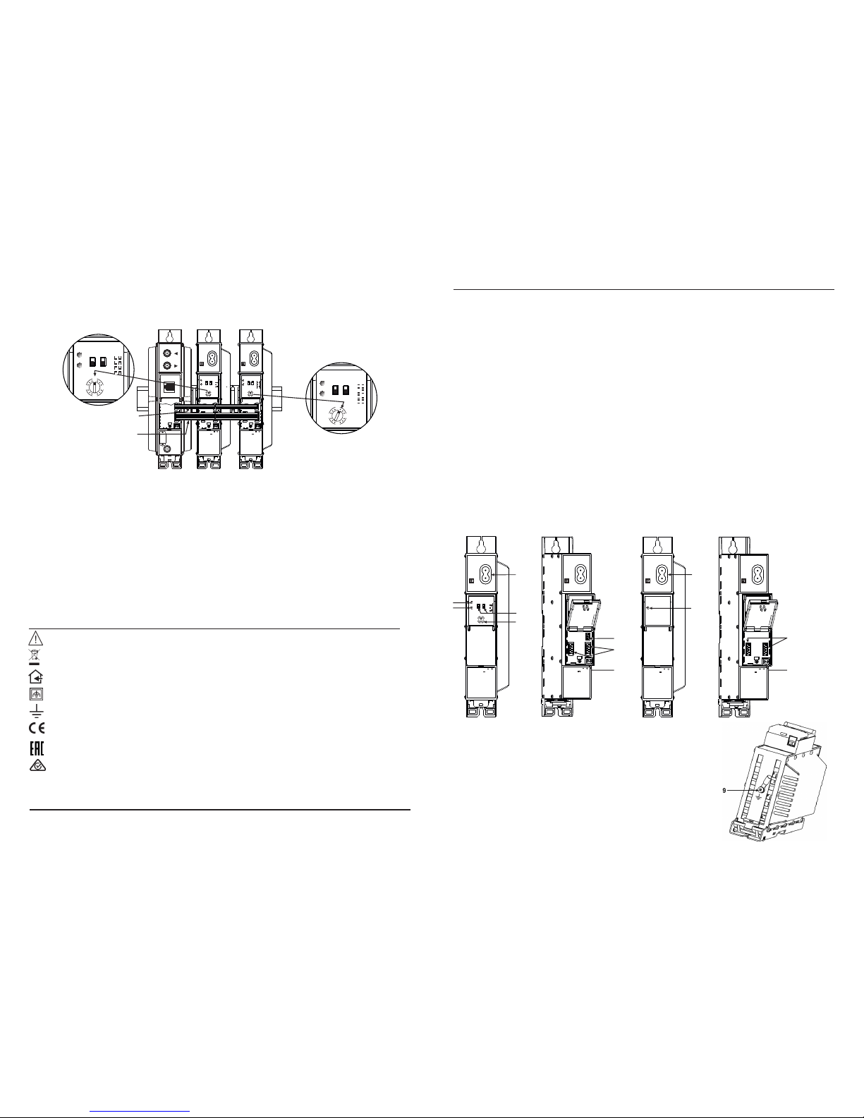
External view
UP412 UP413
TERRA UAB, Draugystes str. 22, LT-51256 Kaunas, Lithuania, Tel.: +370 37
-
31 34 44, fax: +370 37
-
31 35 55
Power supplies UP412, UP413
Figure 1. External view of PSU UP412 and UP413
1- mains connector
2- ADDR. - indicator of addressing (glows when PSU is addressed)
3- ST. - indicator of the module's status (at normal conditions glows green,
at overload or overtemperature glows red)
4- group number setting
5 - module number in group setting
6- data bus connector
7- power distribution bus connectors
8- 12 V output (screw terminal)
9- functional grounding clamp
Installation example
Figure 6. System with 2 PS units UP412 in parallel connection
Caution.
This product complies with the relevant clauses of the European Directive 2002/96/EC. The unit must be
recycled or discarded according to applicable local and national regulations.
Equipment intended for indoor usage only.
Equipment is double insulated from the mains, with functional earthing.
Functional earthing clamp. Crimp Cu wire cross section (1.5-2.5) mm2and connect to main potential equalization.
TERRA conrms, that this product is in accordance to following norms of EU: EMC norm EN50083-2, safety norm
EN60065 and RoHS norm EN50581.
TERRA conrms, that this product is in accordance with Custom Union Technical Regulations: “Electromagnetic
compatibility of technical equipment“ CU TR 020/2011, “On safety of low-voltage equipment“ CU TR 004/2011.
TERRA conrms, that this product is in accordance with safety standard AS/NZS 60065 and EMC standards of Australia.
230V
50/60 Hz
65W max
~
12V 4.5Amax
UP412 Group
No
Module
No
1
2
3
4
ADDR.
ST.
1
9
13 5
230V
50/60 Hz
65W max
~
12V 4.5Amax
UP412 Group
No
Module
No
1
2
3
4
ADDR.
ST.
1
9
13 5
Group No1
Module No 2
Group No1
Module No 1
UP412 Group
No
Module
No
1
2
3
4
ADDR.
ST.
1
9
13 5
UP412 Group
No
Module
No
1
2
3
4
ADDR.
ST.
1
9
13 5
UP412 UP412
mo411AL
power distribution bus
data distribution bus
mo411AL
230 V
50/60 Hz
65W max
~
6
7
8
1
TERRA
230 V
50/60 Hz
65W max
~
2
12V 4.5Amax
UP412 Group
No
Module
No
1
2
3
4
ADDR.
ST.
3
12V 4.5Amax
1
9
13 5
4
5
1
7
230 V
50/60 Hz
65W max
~
UP413
STATUS
TERRA
230 V
50/60 Hz
65W max
~
12V 4.5Amax
3
12V 4.5Amax
8
Vers. 1.01

Installation
When outputs of UP412 and/or UP413 are working in parallel it is recommended to connect PS units to different lines
of the mains or one to the line directly, another via uninterruptable power source (UPS). Disconnected from the mains one
PSU does not disturb parallel working PSU.
Warning!
• Maximal output current of parallel connected PS units can not exeed output current of one PSU.
• Connecting or disconnecting powering of modules must be done when PSU is disconnected from the mains.
• Each device in system connected to the same control bus must have different address.
• Connect in parallel PS units, intended to work in parallel only: UP412+UP412, UP412+UP413, UP413+UP413 (see
gure 6).
• Connection of other model of PSU in parallel with UP412 and/or UP413 is not allowed.
Setting of address
PSU UP412 has possibility to set 64 different addresses – 4 groups, 16 units in each group. To change number of
module number of group not need to disconnect device from the mains.
Example. Need to set module No2 in group No1. To set group No1, group switches turn up. To set module No2, turn
rotary switch to position 2. Now software via TERRA BUS+ protocol will appear UP412 at address 2.
MOUNTING
The module or mounting bracket must be xed with steel screws Ø 3.5-4 mm. The screws are not included in a package.
Mounting on a wall by screws Mounting on a bracket (supplied)
Perpendicular to the wall Parallel to the wall
Figure 2. Mounting of PSU
Mounting on DIN rail
Figure 3. Mounting to DIN rail
Figure 4. Mounting from DIN rail
Figure 5. Mounting or removing to/from
DIN rail of plastic spacers (supplied).
mount 2 spacers between power
supply and other module
Technical characteristics
Supply voltage limit values 187-250 V~ 50/60 Hz
Output voltage 12 V ± 0.5 V
Power consumption 65 W max.
Output current 0-4.5 A short circuit and overload protected
Ripple, 100 Hz < 10 mVpp
Noise < 50 mVpp
Temperature range 0…50°C
Dimensions/Weight (packed) 198x107.5x36 mm/0.97 kg
ma400
DC OUT 12V
0.1A max
DC OUT 12V
0.1A max
TERRA
230V
50/60 Hz
65Wmax
~
12V 4.5Amax
UP412 Group
No
Module
No
1
2
3
4
ADDR.
ST.
1
9
13 6
TERRA
230V
50/60 Hz
65Wmax
~
12V 4.5Amax
UP412 Group
No
Module
No
1
2
3
4
ADDR.
ST.
1
9
13 6
TERRA
This manual suits for next models
1
Other Terra Power Supply manuals


Popular Power Supply manuals by other brands

Videx
Videx 520MR Installation instruction

Poppstar
Poppstar 1008821 Instructions for use

TDK-Lambda
TDK-Lambda LZS-A1000-3 Installation, operation and maintenance manual

TDK-Lambda
TDK-Lambda 500A instruction manual

Calira
Calira EVS 17/07-DS/IU operating instructions

Monacor
Monacor PS-12CCD instruction manual


