Sound Skulptor PSL2 User manual

www.soundskulptor.com
Document revision 1.1 – Last modification : 30/05/08
P L2 Assembly guide
afety warning
THI KIT I NOT FOR BEGINNER !
This kit is main powered and use potentially lethal voltages. Under no circumstance should someone undertake the
realisation of this kit unless he has full knowledge about safely handling main powered devices.
Please read the “DIY guide” before beginning.
Print or open the following documents :
•P L2 chematic
•P L2 Components layout
•P L2 Parts list
•P L2 etup guide
Follow this guide from item number 1 till the end, in this order. The assembly order is based on components height, from
low to high profile, in order to ease the soldering process : The component you are soldering is always taller than the
previously assembled ones and it is pressing nicely against the work area foam.
P L2 Assembly guide
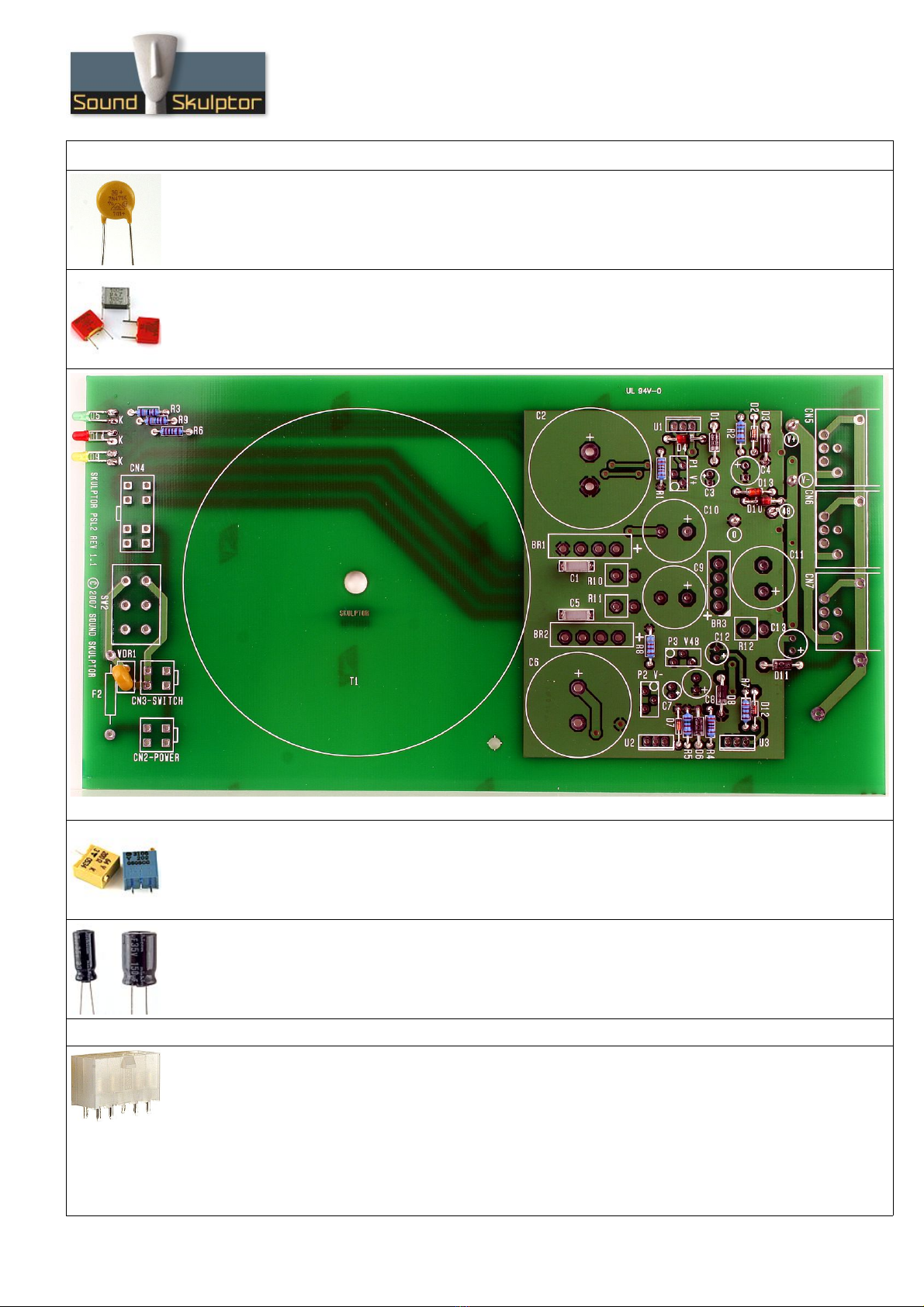
1. Diodes
Add D2, D7, D12, D1, D3, D6, D8, D11, D4, D10, D13. Use a lead forming tool to cleanly bend the
leads at 0.4”.
Warning : Make sure to respect the direction of the diodes which is marked by a ring on the component
and a double line on the PCB marking.
Warning : Do not insert D12 in the wrong hole. It is bended at 0.4” like R7 next to it.
2. Resistors
Add R1 to R9. Control the resistor values with a digital multimeter. Bend the leads at 0.4” with a lead
forming tool.
3. Leds
Add D5, D9, D14
Bend the leads at 7mm from the body taking care of the anode position
(the longest lead).
Warning : it is easy to bend the leads in the wrong direction !
older the LED so it rests on the board. tart by soldering one lead,
adjust the position, then solder the second lead.
4. Test pins
older the 4 test pins TP1 to TP4.
Copyright ©2007 ound kulptor
7.00 mm
Anode : long lead
www.soundskulptor.com
Document revision 1.1 – Last modification : 30/05/08
P L2 Assembly guide
5. VDR1
Add the VDR1 varistor.
6. Film capacitors
Add C1 and C5
7. Trimmer potentiometers
Add P1, P2, P3. older one pin, check verticality then solder the other pins.
8. mall electrolytic capacitors
Add C3, C7, C12, C4, C8
older one lead first, adjust verticality then solder the second lead.
Warning : The +lead must go into the +hole. Do not reverse (they may explode !)
9. PE connectors
Add CN2, CN3, CN4.
On CN4 remove the two central pins. To do this, you must push up the pins as much as possible from
underneath then pull it out with pliers from above.
After soldering, cut the pins flush. The pins are not very long but they carry mains voltage and the
clearance distance between them and the case must be respected.
Warning : Make sure to position the connector in the right direction which is identified by the latching pin
on the PCB.
Copyright ©2007 ound kulptor
www.soundskulptor.com
Document revision 1.1 – Last modification : 30/05/08
P L2 Assembly guide
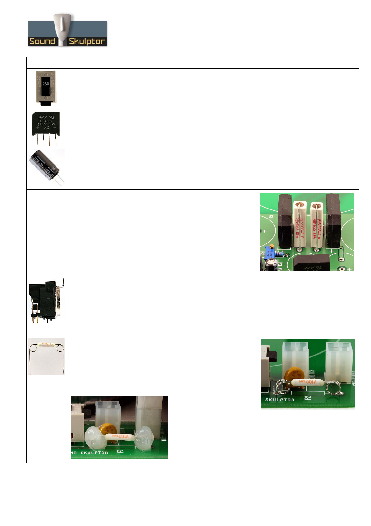
10. 115/230V elector switch
Add W2.
11. Bridge rectifiers
Add BR1, BR2, BR3.
Warning : Make sure to respect the direction of the bridge rectifiers, It is marked by + and - signs.
12. Medium size electrolytics
Add C13, C9, C10
older one lead first, adjust verticality then solder the second lead.
Warning : The +lead must go into the +hole. Do not reverse.
13. 5W resistors
Add R10, R11, R12
The resistors are placed vertically.
Do not hesitate to put some heat on the resistor pins. The solder
sometimes has difficulty sticking to the metal.
Warning : do not confuse 33R (33 Ohms) with R33 (0.33 Ohms).
14. XLR ockets
You need to cut the two small plastic pins on the sockets bottom before you can insert them. Use your
cutters.
The position of the sockets is critical for a good backplate matching. It must sit flat on the PCB. Press
firmly the socket on the PCB and solder one of the centre pins. Check position then solder the other
pins.
15. Thermal fuse F2
Make 2 loops with the legs of the thermal fuse using a screw driver.
Then solder in place quickly : we do not want to blow our fuse with
too much heat.
For security, hide the exposed wires of the thermal fuse with some
silicon sealant.
Copyright ©2007 ound kulptor
www.soundskulptor.com
Document revision 1.1 – Last modification : 30/05/08
P L2 Assembly guide
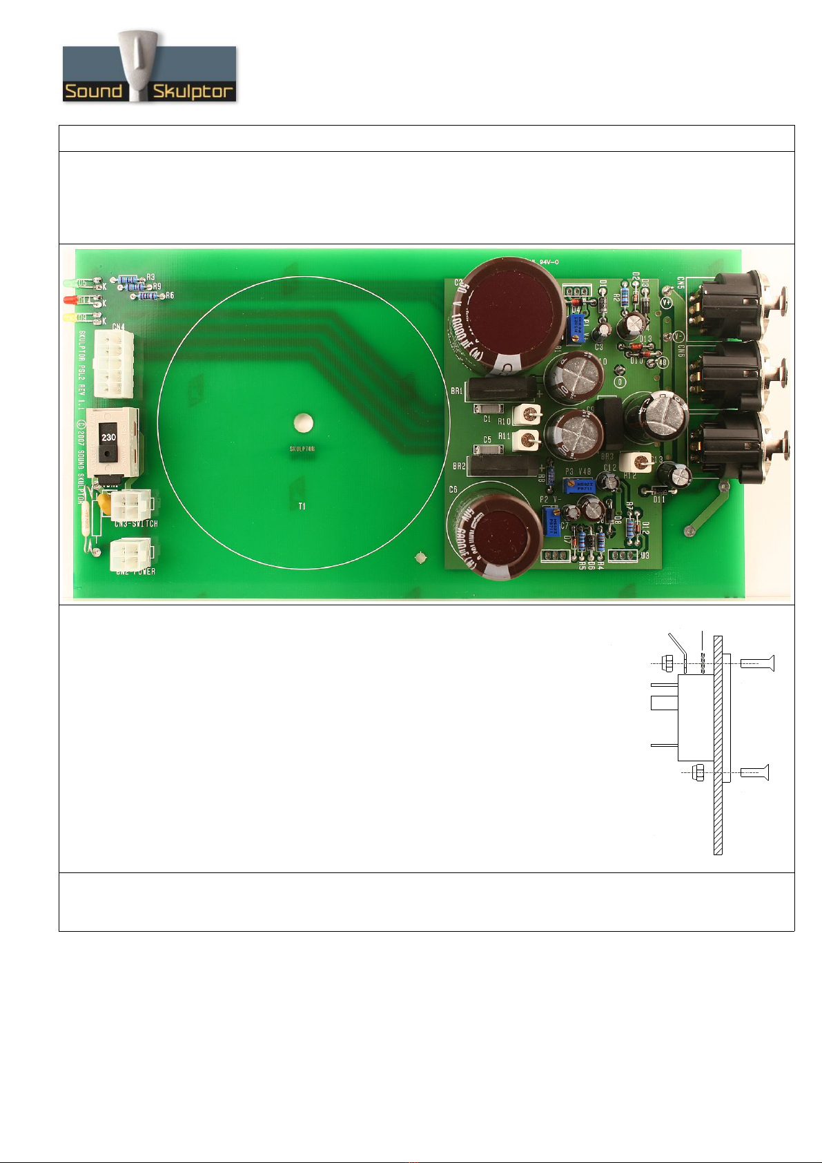
16. Large Electrolytics
Add C11, C2, C6
older one lead first, adjust verticality then solder the second lead.
Warning : The +lead must go into the +hole. Do not reverse.
17. IEC connector assembly
Tie the IEC inlet to the back plate with 2 countersunk screws. M3x12 on
top, M3x10 on bottom. The top screw also takes a shakeproof washer
and a solder tag to make the case connection.
18. Back panel assembly
Tie the back plate to the PCB with 6 self taping screws on the XLR plugs.
Copyright ©2007 ound kulptor
M3x10
M3x12
older tag
hakeproof washer
Back plate

www.soundskulptor.com
Document revision 1.1 – Last modification : 30/05/08
P L2 Assembly guide
19. Earth connection
older 4cm of black insulated wire between the pcb hole and the
earth pin on the IEC connector and 2cm of bare copper wire between
the same earth pin and the solder tag previously attached to the top
screw of the connector.
20. IEC to CN2 wiring
Insert two 15mm pieces of heatshrink tubing on
the 27cm red wires. trip of on 5mm and solder
to the IEC connector pins. Move the tubing on
the pins then heat up with an air gun until it
retracts.
21. IEC insulating
For security, spread some silicon sealant to cover the exposed metal part on the
IEC connector.
22. Front panel wiring
Insert W1 into the front panel.
Insert two 15mm pieces of heatshrink tubing on the 10 cm red wires and solder to the switch. Heat the
tubing with an air gun until it retracts.
Copyright ©2007 ound kulptor
www.soundskulptor.com
Document revision 1.1 – Last modification : 30/05/08
P L2 Assembly guide
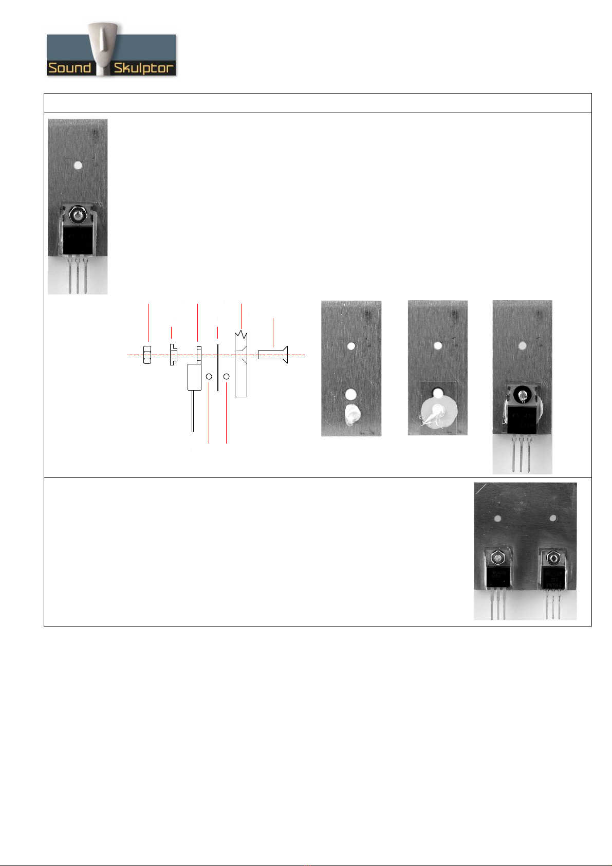
23. ingle heatsink assembly
Place a drop of thermal compound on the heatsink front face, the volume of a grain of rice. The back face
can be identified by the countersunk hole.
Next place the mica insulator.
Place a second drop of thermal compound on the mica insulator.
Insert the M3x10 countersunk screw from the back, the LM350 regulator and the Insulating shoulder
washer.
Place the M3 nut and tighten all together.
Use your digital multimeter in the Ohm position to check that there is no connection between the
heatsink and the center pin of the regulator.
24. Dual heatsink assembly
Repeat the same operations for the two regulators of the dual heatsink.
TL783 on the left,
LM317 on the right.
Copyright ©2007 ound kulptor
M3x10 screw
Heatsink
Thermal compound
Mica
insulator
Regulator
houlder
washer
Nut
www.soundskulptor.com
Document revision 1.1 – Last modification : 30/05/08
P L2 Assembly guide
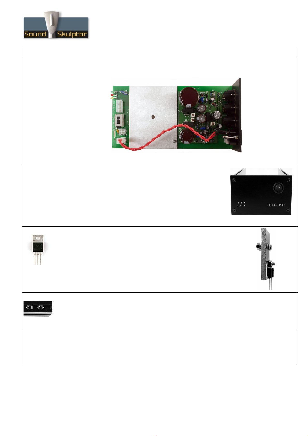
25. Transformer plate assembly
Attach the transformer plate to the PCB with one M3x10 screw and one self locking nut.
26. Case assembly
Assemble the front plate and the two sides of the case with four black M4
countersunk screws.
The internal face of the sides is the one with two grooves.
27. Regulators heatsink assembly
Place one and two M3x10 pan head screws with two nuts on the regulator heatsinks.
Insert the regulator pins into the PCB. Do not solder yet.
28. Top and bottom cover fixing nuts
Add 2 nuts in the top and bottom grooves of both sides of the case (for a total of 8 nuts). They will be
used to attach top and bottom covers.
29. PCB insertion
Insert the PCB into position by sliding the heatsink screws into the case grooves. Make sure the LEDs fit
into the front plat holes.
Copyright ©2007 ound kulptor

www.soundskulptor.com
Document revision 1.1 – Last modification : 30/05/08
P L2 Assembly guide
30. Back plate assembly
Attach the back plate with four M4 countersunk screws.
31. Heatsinks assembly
Tighten firmly the fixing screws of both heatsinks.
older the 3 regulators. Cut the pins flush.
32. Connectors plugging
Insert CN2 (from IEC connector) and CN3 (On/Off switch) in their respective sockets.
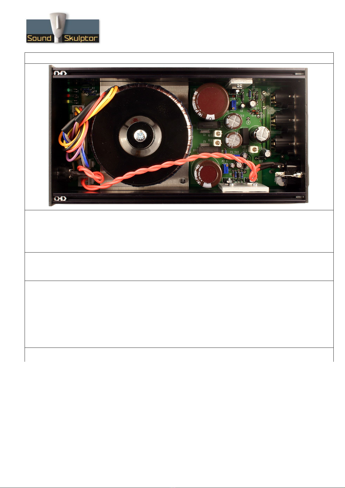
33. Transformer installation
Attach the transformer. The nut should be
tightened to prevent any transformer movement
but without crushing the windings.
Plug in the transformer connector.
Copyright ©2007 ound kulptor
Transformer plate
oft washer
oft washer
Transformer
Mounting disc
Nut
PCB
www.soundskulptor.com
Document revision 1.1 – Last modification : 30/05/08
P L2 Assembly guide
34. Visual check
Brush the solder side of the PCB with a hard tooth brush to remove any remaining solder bits.
Make a full visual check. Any missing component on the board ? Any remaining component in the box ?
35. etup
Your P L2 is now ready for test and setup. Please follow instructions in the “P L2 etup” document.
36. Closing the case
With the help of the bottom cover, position the fixing nuts in front of the holes.
Place the bottom cover and secure it with 4 black screws.
Place the top cover and secure it with 4 black screws.
tick the four self adhesive rubber feet on the bottom of the case.
tick the warning label on the bottom of the case.
37. Congratulations, you're done !
Copyright ©2007 ound kulptor
Other Sound Skulptor Recording Equipment manuals


