7700 MultiFrame Manual
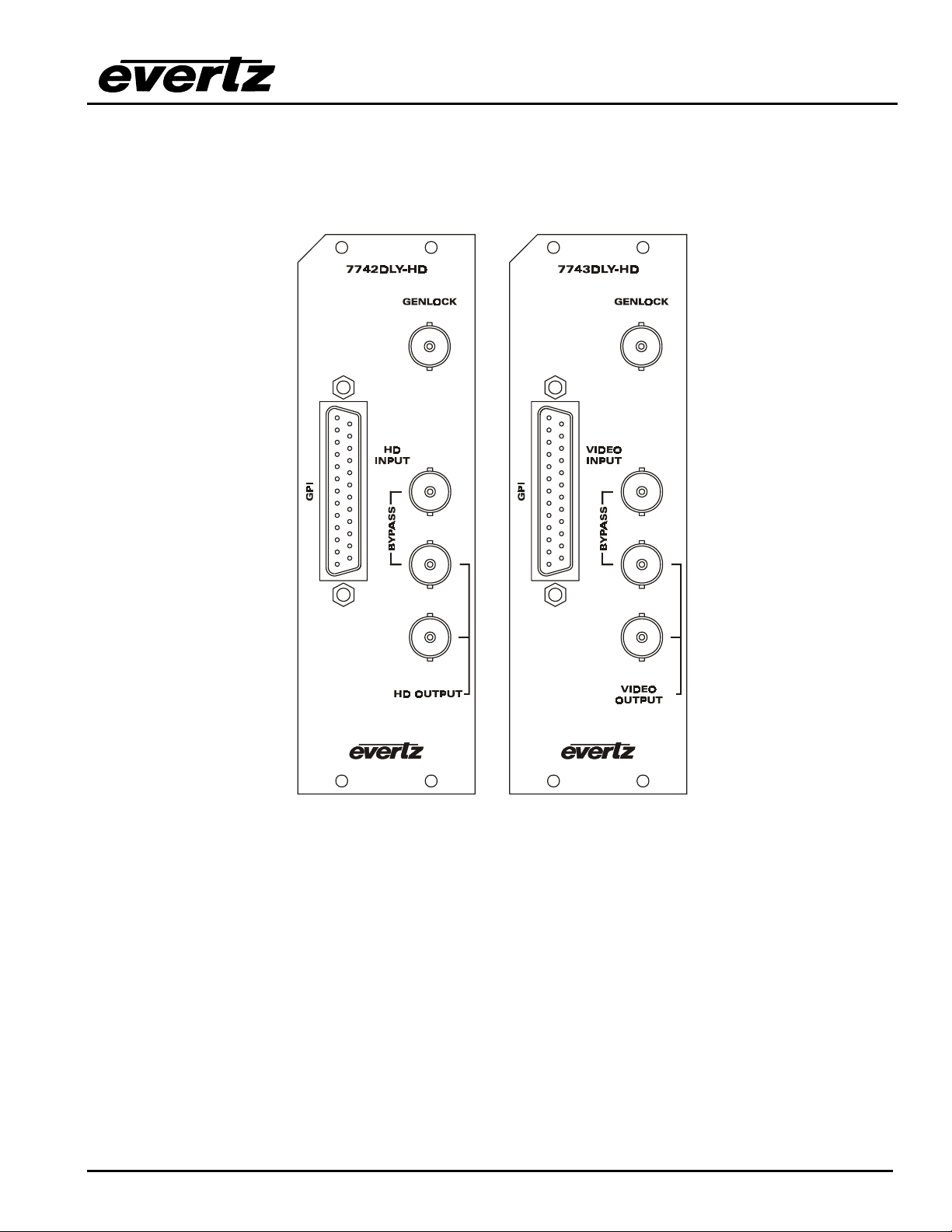
7740DLY-HD series HD Video Delay
Revision 1.3.1 7740DLY-HD-5
3. SPECIFICATIONS
3.1. SERIAL VIDEO INPUT
3.1.1. High Definition Serial Digital Video
Standard: SMPTE 292M (1.5 Gb/s)
Connector: BNC per IEC 60169-8 Ammendment 2.
Equalization: Automatic to 75m @ 1.5 Gb/s with Belden 1694 or equivalent cable
Return Loss: > 15 dB up to 1.0 Gb/s
> 10 dB up to 1.5 Gb/s (with relay)
3.1.2. Standard Definition Serial Digital Video (model 7743-DLY-HD only)
Standard: SMPTE 259M (270 Mb/s)
Connector: BNC per IEC 60169-8 Ammendment 2.
Equalization: Automatic
Max. Cable Length: Automatic to 300m @ 270 Mb/s with Belden 8281 or equivalent cable
Return Loss: > 15 dB up to 270 Mb/s
3.2. SERIAL VIDEO OUTPUTS
3.2.1. HD Serial Digital Video
Number of Outputs: 1 with relay bypass, 1 additional output.
Connector: BNC per IEC 60169-8 Ammendment 2.
Signal Level: 800mV nominal
DC Offset: 0V ±0.5V
Rise and Fall Time: 200ps nominal
Overshoot: <10% of amplitude
Return Loss: > 15 dB up to 1.5 Gb/s
Wide Band Jitter: < 0.2 UI
3.2.2. Standard Definition Serial Digital Video (model 7743-DLY-HD only)
Number of Outputs: 1 with relay bypass, 3 additional outputs.
Connector: BNC per IEC 60169-8 Ammendment 2.
Signal Level: 800mV nominal
DC Offset: 0V ±0.5V
Rise and Fall Time: 740ps nominal
Overshoot: <10% of amplitude
Return Loss: > 15 dB up to 540 Mb/s
Wide Band Jitter: < 0.2 UI
3.3. GENLOCK INPUT
Type: HD Tri-level Sync, (SeeTable 3)
NTSC or PAL Colour Black 1 V p-p, or
Composite bi-level sync (525i/59.94 or 625i/50) 300 mV
Connector: BNC per IEC 60169-8 Ammendment 2.
Termination: 75 ohm (jumper selectable)