Sound Skulptor TS500 User manual
www.soundskulptor.com
Document revision 1.3 – Last modification : 21/04/21
T 500 Assembly guide
afety warning
The kits are main powered and use potentially lethal voltages. Under no circumstance should someone undertake the
realisation of a kit unless he has full knowledge about safely handling main powered devices.
Please read the “DIY guide” before beginning.
Print or open the following documents :
• T 500 chematics
• T 500 Components layout
• T 500 Parts list
• T 500 etup guide
Follow this guide from item number 1 till the end, in this order. The assembly order is based on components height, from
low to high profile, in order to ease the soldering process : The component you are soldering is always taller than the
previously assembled ones and it is pressing nicely against the work area foam.
oldering
All the PCB holes are metallized. It means the connection between the top and bottom pads is already
done. The parts must be soldered only from below (unless differently stated).
Use only small diameter solder, 0.5 or 0.7 mm, 1mm maximum. Use the minimum possible amount of
solder. Bad joints are almost always caused by too much solder.
Cut the component leads and pins totally flush with the PCB after soldering. A too long tail could create
an electric connection with the side plate.
Here are two excellent introduction to soldering videos:
http://www.eevblog.com/2011/06/19/eevblog-180-soldering-tutorial-part-1-tools/
http://www.eevblog.com/2011/07/02/eevblog-183-soldering-tutorial-part-2/
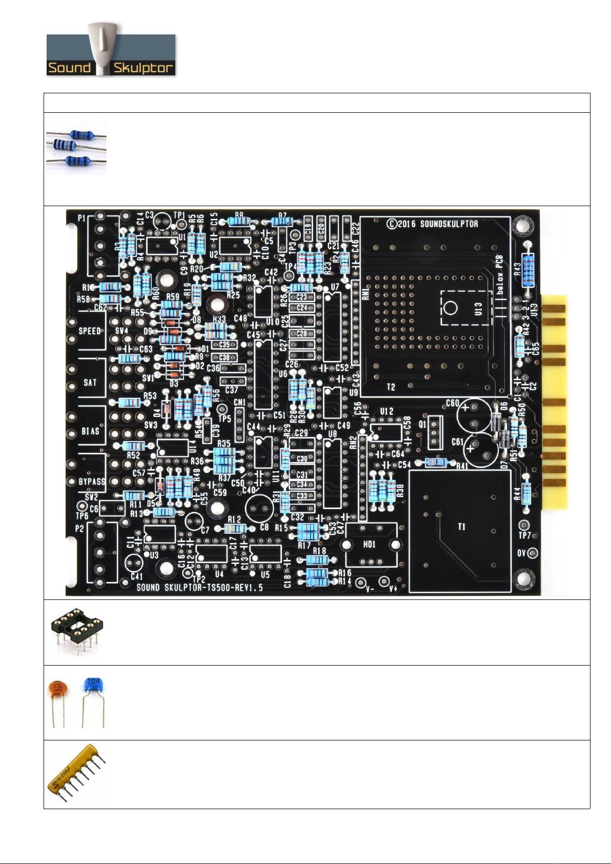
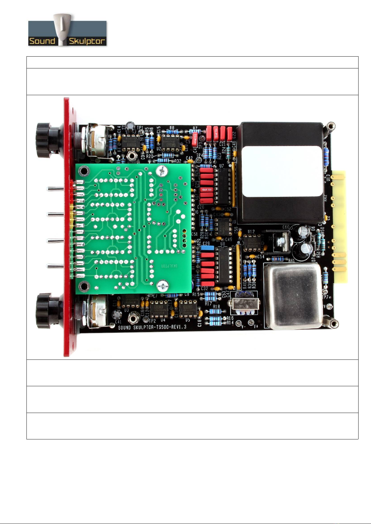
T 500 Assembly guide – Main PCB
1. Diodes
tart by D1 and D2. Then add D3, D4, D5, D8, D9 and finally D6, D7. Use a lead forming tool to bend
the leads at 0.4”.
Warning : Make sure to respect the direction of the diodes which is marked by a ring on the component
and a double line on the PCB marking.
D1 and D2 are Zener diodes and must not be confused with the 1N914. They are in a group of 2 while
the 1N914 are a group of 5 in the kit.
2. Resistors – (1)
The best method to select and install the resistors is the following:
1. pick a row of resistors in the resistors bag,
2. Measure one of the resistors with your DMM,
3. Look up the parts-list PDF for the closest value,
4. Check the color code and quantity for confirmation,
5. Use the search function on the Layout PDF page with the resistor value: All the corresponding
resistors are highlighted,
6. Insert and solder.
(You can use the same method later, for the capacitors)
Copyright ©2016 to Today ound kulptor
www.soundskulptor.com
Document revision 1.3 – Last modification : 21/04/21
T 500 Assembly guide – Main PCB
3. Resistors - (2)
Add R1 to R60. Control the resistor values with a digital multimeter. Bend the leads at 0.4” with a lead
forming tool, except for R43 which is bent at 0.6”.
Warning : It is very important to check the resistors value with a DMM because the colour code can be
ambiguous. For example 1K (brown-black-black-brown-brown) can be confused with 110R (brown-brown-
black-black-brown).
4. IC ockets
Insert and solder the ten 8 pins sockets and three 16 pins sockets.
Warning : Make sure to respect the socket direction, marked by a notch.
5. Ceramic capacitors
Add C54, C64, C65.
Add C1, C2, C5, C40, C55.
Add C9, C10, C11, C12, C13, C14, C15, C16, C17, C18, C42, C43, C44, C45, C46, C47, C48,
C49, C50, C51, C52, C53, C56, C57, C58, C59, C62, C63.
6. Resistor networks
Add RN1 and RN2.
Warning : the resistor networks are polarized and must be mounted in the right direction identified by a
dot on the resistor network and a dot on the PCB.
Copyright ©2016 to Today ound kulptor

www.soundskulptor.com
Document revision 1.3 – Last modification : 21/04/21
T 500 Assembly guide – Main PCB
7. Test pins
older the 10 test pins TP1 to TP7, V+, V- and 0V.
8. Film capacitors
Add C35, C22, C36, C37, C21, C38, C27, C4, C20, C28, C39, C26, C33, C19, C34, C24, C32,
C25, C23, C30, C31, C29, C6.
Warning : Be very careful to place the right caps in the right places because once soldered, it is
impossible to read their value.
9. Connector
Add CN1. older one pin, check verticality then solder the other pins.
10. Non polarized electrolytic capacitors
Add C3, C7, C41, C8.
These caps are not polarized and can be inserted in any direction.
Copyright ©2016 to Today ound kulptor

www.soundskulptor.com
Document revision 1.3 – Last modification : 21/04/21
T 500 Assembly guide – Main PCB
11. Polarized electrolytic capacitors
Add C60, C61.
Warning : The +lead must go into the +hole. Do not reverse (they may explode !)
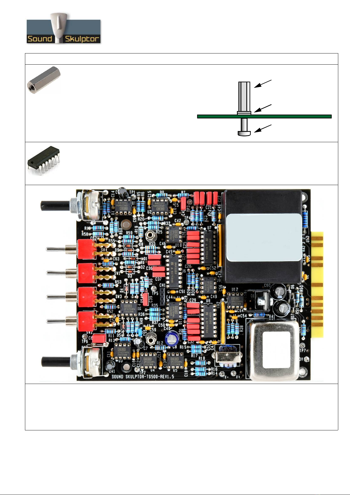
12. Tape head simulation coil
Insert and solder HD1
13. U13
U13 must be installed
on the back
of the PCB. Bend the
leads at the correct distance and insert the part flat on
the PCB. The U13 body must rest entirely on the shiny
metal. older leads.
Now solder the metal tab to the PCB. tart by heating the
metal tab any apply solder to it until the solder flows down
to the PCB.
14. witches
Add W1 to W4. The position of the switches is critical for a good front-plate matching. They must sit
flat on the PCB. Press firmly the switch on the PCB and solder one of the front pins (housing). Check
verticality and horizontality. Then solder the other pins.
15. Input transformer
Insert and solder the input transformer.
16. Potentiometers P1 & P2
Place the bracket on the potentiometer bushing, and attach it with the lock washer and nut. Tighten.
Insert potentiometer and bracket into the PCB holes. older the central potentiometer pin. Now check
that the potentiometer shaft is perfectly parallel to the board.
Warning : Do not only rely on the bracket being flat on the PCB, it sometimes need little visually made
adjustments to get a perfect position.
Warning : The two potentiometers have the same Ohmic value but P1 is linear and P2 is logarithmic.
Once the position is correct, solder the other pins.
17. Power transistor Q1
Mount Q1 on the heatsink with a M3x6 mm screw and a self locking
nut.
Insert Q1 and solder one pin. Check the verticality then solder the
other pins.
18. Output transformer
Insert and solder the output transformer.
Copyright ©2016 to Today ound kulptor
www.soundskulptor.com
Document revision 1.3 – Last modification : 21/04/21
T 500 Assembly guide – Main PCB
19. Gain reduction meter spacers
Insert a M3x10 mm screw from below PCB, add
two metal washers and the 20mm spacer.
Repeat for the second spacer.
20. IC's
Insert U1 to U12, U14 into their sockets. It is necessary to bend the pins slightly inward before
inserting.
Warning : Make sure to insert the IC's in the correct direction which is identified by a notch.
21. Visual check
Brush the solder side with a hard tooth brush to remove any remaining solder bits.
Make a full visual check. Any missing component on the board ? Any remaining component in the box ?
When everything looks correct, proceed with the meter PCB assembly.
Copyright ©2016 to Today ound kulptor
2 Washers
Spacer
M3x10 mm screw
www.soundskulptor.com
Document revision 1.3 – Last modification : 21/04/21
T 500 Assembly guide – Meter
1. LEDs
For each one of the 16 LED's cut the short leg (cathode) at 5mm from
body and cut the long leg (anode) at 6mm.
Then insert the first green LED on the PCB, long leg (anode) on top. Make
sure that the leg is perfectly parallel to the pad. older the anode but
leave the cathode free for now. The position is still easy to adjust until both
legs are soldered.
Insert and solder the next LED and repeat until the16 LEDs are in position.
Make a last visual check and correct LED's that are not perfectly lined up, then solder the cathodes on
the PCB back side.
2. Resistors
Add R1 to R19. R20 is not connected.
Control the resistor values with a digital multimeter. Bend the leads at 0.4” with a lead forming tool.
3. Integrated Circuits
Insert U1, U2, U3 and U4 and solder. You will need to bend the pins slightly inwards before inserting.
Warning : Make sure to respect the IC direction, marked by a semi-circular notch on the IC and a dot on
the PCB.
4. Ceramic capacitor
Add C3.
5. Trimmer potentiometer
Add P1.
6. Regulator IC's
Add U5 and U6. Press the IC's down as far as possible in order to keep the components height low.
Warning : Watch out the IC direction.
7. Electrolytic capacitors
Add C1, C2, flat on the PCB.
Warning : The +lead must go into the +hole. Do not reverse (they may explode !)
Copyright ©2016 to Today ound kulptor

www.soundskulptor.com
Document revision 1.3 – Last modification : 21/04/21
T 500 Assembly guide – Meter
8. 4 pins connector
older the 4 pins connector. older one pin first, check verticality, then solder the other pins.
Warning : the connector pins must be exactly perpendicular to the PCB to allow proper insertion into the
T 500 board.
T 500 Assembly guide – Final assembly
9. Meter assembly
Insert the meter connector into the corresponding
socket and attach on the two 20mm spacers with two
M3x6 screws.
10. Front panel and ide plate assembly
Attach the side panel to the front plate with two
M3x6 black countersunk screws.
11. PCB assembly
Put the PCB in place, switches and pots going through the front panel. Attach the PCB with 4 M3x25mm
spacers and 4 lock-washers.
Copyright ©2016 to Today ound kulptor
www.soundskulptor.com
Document revision 1.3 – Last modification : 21/04/21
T 500 Assembly guide – Final assembly
12. Knobs
Attach the 2 knobs to the 2 potentiometers.
13. Test and setup
It is time for test and setup. Follow instructions on T 500-setup-guide.pdf.
14. Closing
Attach the cover PCB with four M3x6 countersunk screws.
15. Congratulations !
You're done !
Copyright ©2016 to Today ound kulptor
Table of contents
Other Sound Skulptor Recording Equipment manuals


