Soundchoice PROAudio C2 Series User manual

C2 Series Commercial
Class-D Two Channel Amplifier
INSTALLATION AND OPERATION MANUAL

2 / 11
1. Read these instructions.
2. Keep these instructions.
3. Heed all warnings.
4. Follow all instructions.
5. Do not use this apparatus near water.
6. Clean only with dry cloth.
7. Do not block any ventilation openings. Install in accordance with the manufacturer’s instructions.
8. Do not install near any heat sources such as radiators, heat registers, stoves, or other apparatus (including amplifiers) that
produce heat.
9. Do not defeat the safety purpose of the polarized or grounding-type plug. If the provided plug does not fit into your outlet, consult an
electrician for replacement.
10. Protect the power cord from being walked on or pinched particularly at plugs, convenience receptacles, and the point where they
exit from the apparatus.
11. Only use attachments/accessories specified by the manufacturer.
12. Use only with the cart, stand, tripod, bracket, or table specified by the manufacturer, or sold with the apparatus. When a cart is used,
use caution when moving the cart/apparatus combination to avoid injury.
13. Unplug this apparatus during lightning storms or when unused for long periods of time.
14. Refer all servicing to qualified service personnel. Servicing is required when the apparatus has been damaged in any way, such
as power-supply cord or plug is damaged, liquid has been spilled or objects have fallen into the apparatus, the apparatus has been
exposed to rain or moisture, does not operate normally, or has been dropped.
15. This appliance shall not be exposed to water and that no object filled with liquid such as vases shall be placed on the apparatus.
16. Plug this apparatus to the proper wall outlet and make the plug easily removable.
17. WARNING: To reduce the risk of fire or electric shock, do not expose this apparatus to rain or moisture.
18. An appliance with a protective earth terminal should be connected to a mains outlet with a protective earth connection.
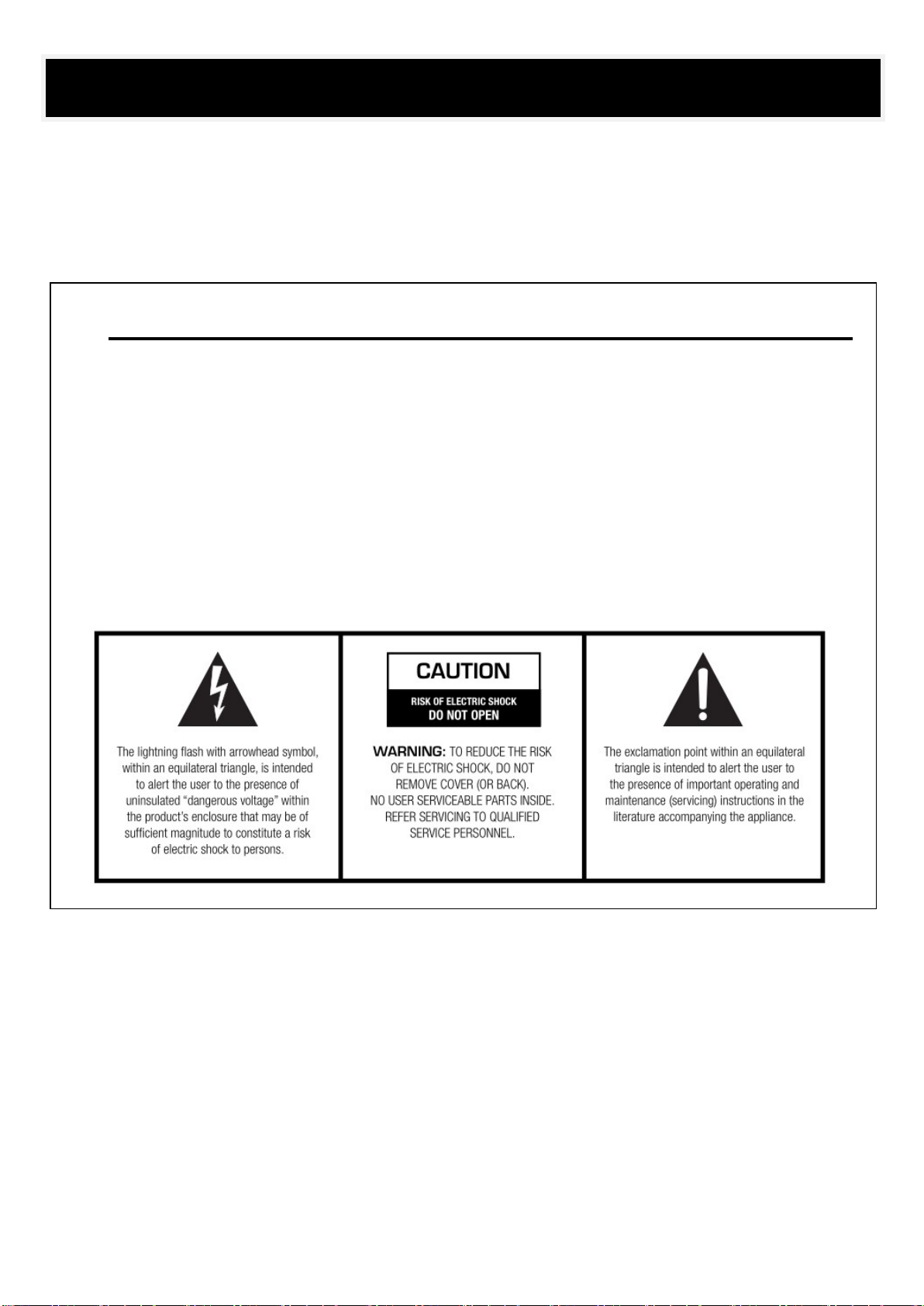
Important Safety Information
3 / 11
WARNING!
TO PREVENT FIRE OR SHOCK HAZARD, DO NOT USE THE PLUG WITH
AN EXTENSION CORD, RECEPTACLE OR OTHER OUTLET UNLESS THE BLADES
CAN BE FULLY INSERTED TO PREVENT BLADE EXPOSURE.
TO REDUCE THE RISK OF FIRE OR ELECTRIC SHOCK, DO NOT EXPOSE
THIS APPLIANCE TO RAIN OR MOISTURE.
TO PREVENT ELECTRICAL SHOC
K, MATCH WIDE BLADE PLUG TO WIDE SLOT, FULLY INSERT.
Safety Warning

4 / 11
Front Page-------------------------------------------------------------------------------------------------------------------------------------------------1
Important Safety Information------------------------------------------------------------------------------------------------------------2
Safety Warning------------------------------------------------------------------------------------------------------------------------------3
Contents-------------------------------------------------------------------------------------------------------------------------------------4
Introduction---------------------------------------------------------------------------------------------------------------------------------5
Front Panel----------------------------------------------------------------------------------------------------------------------------------6
Rear Panel-----------------------------------------------------------------------------------------------------------------------------------7
Speaker Connection------------------------------------------------------------------------------------------------------------------------8
Block Diagram-------------------------------------------------------------------------------------------------------------------------------9
Specification-------------------------------------------------------------------------------------------------------------------------------10
Service and Warranty---------------------------------------------------------------------------------------------------------------------11
Contents

5 / 11
Features:
Switching technology digital power amplifier
Class-D PA power amplifier with minimum power consumption
Less rack space and less heat generation
Two channel power amplifier into 19” rack mount unit
Two channel separate speaker outputs 4Ω/100V
Balanced line inputs by phoenix connector
Each input with separate gain control.
Each channel with high-cut filter
Built-in auto standby feature to save power consumption
Separate channel indicators for protection, clip, input and output
Complete short circuit, overload, high temp, clip and DC
protection
Wide AC input 230V input
24V DC battery input included
Description:
The C2 series digital class-D power amplifier uses
switching power technology, which features minimum power
consumption and much higher efficiency up to 85%, moreover it
helps to save installation rack space, generate less heat so as to
extend its performance life span as a result.
The digital class-D amplifiers are of rated power output from 120W to
500W by two channels, so it could be used as two zone multiple
sources public address system at minimum cost. The versatile
loudspeaker outputs of both high impedance 100V & low impedance
8 Ohms gives flexibility for installation.
There are two balanced line inputs by phoenix connector for each
channel with gain control. Two separate speaker outputs both
by 100V or 8 Ohms. The built-in two channel separate high-pass
filters can be enabled or disabled through the dip switch
settings.
Automatic standby enable after no detection of signal input for one
minute, immediately start when signal is detected. Visual working
status indicators include protection, clip, input and output for easy
supervision. With complete short circuit, overload, high temp, clip
and DC protection.
Wide AC power supply of 230V, thus it support worldwide sound
system installation. 24V DC battery input is included.
Introduction
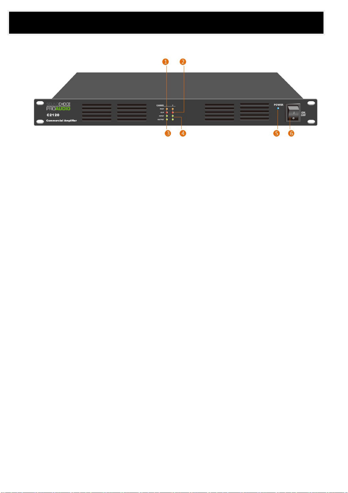
6 / 11
1. PROT
Protection indicator will light orange once the amplifier comes into protection status. The protection maybe resulted from speaker
line short circuit, speaker line open circuit, amplifier overload and working temperature over 55℃, this indicator give visually
guidance. The light will turn off once fault is repaired. There are two separate protection indicators one for each channel.
2. CLIP
Clip indicator will light red once the input or output is too high. There are two separate CLIP indicators one for each channel.
3. INPUT
Input indicator will light green once there is any input signal detected. There are two separate input indicators one for each channel.
4. OUPUT
Output indicator will light green once there is output signal detected. There are two separate output indicators one for each channel.
5. POWER
Power indicator will be light blue once the unit has been powered by AC or DC.
6. POWER SWITCH
Power switch used to power on and power off the equipment.
Front Panel

7 / 11
1. AC POWER SOCKET
AC power cord for input of 230V, 50-60Hz for main power input.
2. 24V DC POWER INPUT
24V DC power supply input as supply will automatically in standby use when AC mains fails.
3. LINE INPUT(1-2 Channel)
The line input support both balanced or unbalanced inputs from audio sources or mixer, these input are by phoenix connectors. There
are two channel separate line inputs which could be managed respectively. (NOTICE: For unbalanced line input, “-“ and “GND” shall
be tied together)
4. GAIN CONTROL
The gain control is used to adjustment the input sensitivity for various inputs to achieve the best response. There are separate gain
control one for each channel.
5. 100V SPEAKER OUTPUT(PIN1=COM & PIN3=100V +)
The speaker outputs shall be connected to 100V line loudspeakers, the negative end to the speaker negative and the positive end to
the speaker positive. These speaker output are supplied using phoenix connectors.
Never mixed the negative end and the positive, which will cause the short circuit protection.
Never connection the low impedance loudspeaker to the 100V outputs, this will damage the speaker or have heavy distortion.
6. 8Ω SPEAKER OUTPUT
The speaker outputs shall be connected to low impedance 8Ω loudspeakers, the negative end to the speaker negative and the
positive end to the speaker positive. These speaker output are supplied using phoenix connectors.
Never mixed the negative end and the positive, which will cause the short circuit protection.
Never connect the 100V line loudspeaker to the 8Ω output, this will burn the speaker or have heavy distortion.
7. AUTO-STANDBY (DIP1-2)
The Auto standby function will be enabled or disabled by pre-setting the dipswitches. The enabled auto-standby function will
automatically go into standby once there is no input detected for 2 minutes. The amplifier will immediately wake up once there is
detection of input signal. Separate auto-standby dipswitches for each channel.
8. HIGH PASS FILTER (DIP3-4)
The high pass filter function will be enabled or disabled by pre-setting the dipswitches. Separate high pass filter dipswitches for each
channel.
Rear Panel

8 / 11
Before connecting speakers, disconnect the AC power cable. Note the proper connecting terminals as shown below. Make sure that the total
impedance is not less than the rated impedance indicated.
Before connecting speakers, disconnect the AC power cable. Note the proper connecting terminals as shown below. Make sure that the
total impedance is not less than the rated impedance indicated.
- Connecting 4-16Ω Speaker Systems
When connecting conventional 4-16Ω speaker systems, connect the speaker’s positive (+) side to the terminal labeled 4-16Ω. Connect
the speaker’s negative (-) side to the terminal labeled COM.
- Connecting High-Voltage Distributed Speaker Systems
When connecting a high-impedance (100V) speaker system in parallel, connect the speaker’s positive (+) side to the terminal labeled
100V. Connect the speaker’s negative (-) side to the terminal labeled COM.
FOR 4Ω LOW IMPEDANCE SPEAKER CONNECTION FOR 8Ω LOW IMPEDANCE SPEAKER CONNECTION
FOR 100V SPEAKER WITH TRANSFORMER CONNECTION WRONG SPEAKER CONNECTION
Speaker Connection

9 / 11
Block Diagram

10 / 11
Model C2120 C2240 C2350 C2500
Description Class-D Two Channel Power Amplifier
Rated Power Output 2x120W 2x240W 2x350W 2x500W
Speaker Output 8Ω & 100V
Frequency Response L/H Cut OFF 20Hz-20KHz (+1/-2dB)
L/H Cut ON 70Hz-10KHz (+1/-3dB)
Input 0.775V, 0dBu, balanced phoenix connector by two channels
Input Impedance 10KΩ
THD <0.1% (1KHz/-3dBv, 100W)
S/N Ratio >80dB
Crosstalk >60dB, 1KHz, Max output
Power Consumption 300W 550W 800W 1150W
Power Supply AC input from 110V & 230V, 50-60H, with DC24V input
Dimension 482(W)x420(D)x44(H) mm
Weight 6.5kg 7.5kg 8kg 8.5kg
Specifications

11 / 11
Service
Procedures
Ensure the problem is not related to operator error, or system devices that are external to this unit. Information provided in the
troubleshooting portion of this manual may help with this process. Once it is certain that the problem is related to the product contact your
warranty provider as described in the warranty section of this manual.
Variations and Options
Variations
Products supplied through legitimate sources are compatible with local AC power requirements.
Options
No optional items are available for this product.
Warranty
Warranty terms of global three years. While the term and warranty may vary by country and may not be the same for all products. Terms
and conditions of warranty for a given product may be determined first by locating the appropriate country which the product was
purchased in, then by locating the product type.
www.scpaudio.com
Specifications may change without notice.
Service & Warranty
This manual suits for next models
4
Table of contents
Other Soundchoice PROAudio Amplifier manuals

Soundchoice PROAudio
Soundchoice PROAudio CA2120 User manual

Soundchoice PROAudio
Soundchoice PROAudio 4120A User manual

Soundchoice PROAudio
Soundchoice PROAudio 2120A User manual

Soundchoice PROAudio
Soundchoice PROAudio 120MA User manual

Soundchoice PROAudio
Soundchoice PROAudio T-60FP User manual

Soundchoice PROAudio
Soundchoice PROAudio C4 Series User manual

Soundchoice PROAudio
Soundchoice PROAudio A4 Series User manual

Soundchoice PROAudio
Soundchoice PROAudio CA4360 User manual


 user manual")


