Soundfield UPM-1 User manual
SoundField UPM-1
Stereo to 5.1 Converter
User Guide
Version 1.0
SOUNDFIELD

Page 2
CONTENTS:
Safety Information - - - - - - - - - - 3
Introduction - - - - - - - - - - - 4
Example Application: Stadium Sports - - - - - - - 5-6
Controls-----------7-10
Audio Specification - - - - - - - - - - 11
Warranty-----------12
Shipping and Quality Assurance - - - - - - - 13
Contents
SoundField UPM-1 User Guide

SoundField UPM-1 User Guide
Page 3Safety Information
SAFETY INFORMATION
• This equipment must be EARTHED.
• Only suitably trained personnel should service this equipment.
• Please read and take note of all warning and informative labels.
• Before starting any servicing operation, this equipment must be isolated from the AC supply (mains) by removing the
incoming IEC mains connector.
• Fuses should only be replaced with ones of the same type and rating as that indicated.
• Operate only in a clean, dry and pollutant-free environment.
• Do not operate in an explosive atmosphere.
• Do not allow any liquid or solid objects to enter the equipment. Should this accidentally occur then immediately
switch off the unit and contact your service agent.
• Do not allow ventilation slots to be blocked.
Cleaning
For cleaning the front panels of the equipment we recommend anti-static screen cleaner sprayed onto a soft cloth to
dampen it only.
Explanation of Warning Symbols
The lightening flash with arrow head symbol within an equilateral triangle is
intended to alert the user to the presence of dangerous voltages and energy levels
within the product’s enclosure that may be of sufficient magnitude to constitute a
risk of electric shock or injury.
The exclamation mark within an equilateral triangle is intended to prompt the user to
refer to important operating or maintenance (servicing) instructions in the
documentation supplied with the product.

Page 4Introduction
INTRODUCTION
The UPM-1: What Is It?
The SoundField UPM-1 is a fully digital Stereo to 5.1 converter aimed at broadcast applications.
The progression from standard definition (SD) to high definition (HD) broadcasting brings with it
the requirement for a digital 5.1 audio stream. In many working environments broadcasters find
themselves in situations where they need to introduce previously recorded stereo material into an
HD 5.1 audio stream. A typical example would be in the coverage of major sporting tournaments
where short extracts of archived material from previous years’ winning performances need to be
inserted. Folding the audio back down to stereo momentarily is unacceptable - the UPM-1 will
take any digital stereo input signal and create a natural sounding 5.1 mix. No effects such as
reverb are used and only the original components of the stereo source material will appear in the
5.1. The UPM-1 uses a unique algorithm which extracts the ambience from the direct sound and
differentiates itself from other approaches to upmixing through its adaptive nature. The detailed
real-time analysis of the stereo input material will determine how the upmix algorithm behaves at
that instance in time.
The aim of the UPM-1 is to produce a very stable and natural sounding 5.1 without destroying the
original stereo image. Key to achieving this are:
The UPM-1 has two main modes of operation - Upmix mode and Matrix Decode mode. The main
difference between these two modes is in how the surround channels are derived. In Upmix mode
no direct sound is sent to the rear channels - only ambience. In Matrix Decode mode the UPM-1
will detect any stereo material which has been matrix encoded (Dolby® Pro Logic® etc) and any
direct sound intended by the encoding process for the rear surround will be sent there. It is
important to note that with non-matrix encoded material both modes will behave identically.
There are three controls central to the UPM-1’s operation: Front Direct Sound, Front Ambient
Sound and Rear Ambient Sound. By adjusting these three controls the user can create a desired
balance between direct and ambient sound within the 5.1 surround. Two further controls, Width
and Centre Divergence, provide the opportunity for further fine adjustment to imaging and centre
channel content. The effect of all these controls is explained in greater detail in the next section:
EXAMPLE APPLICATION: STADIUM SPORTS.
SoundField UPM-1 User Guide
Dolby is a registered trademark of Dolby Laboratories.
Pro Logic is a registered trademark of Dolby Laboratories.
• Good extraction of mono sources to feed the centre channel - such as dialogue,
commentary, etc.
• Maintaining the frontal stereo image by keeping the direct sound sources of the stereo mix
at the front.
• Only the extracted natural ambience is fed to the rear surround sound channels.

SoundField UPM-1 User Guide
Page 5Example Application: Stadium Sports
EXAMPLE APPLICATION: STADIUM SPORTS
STEREO MIX INPUT made up of:
• Commentary - panned centre (phantom centre)
• Effects (such as ball kicks and sound effects) - stereo Left/Right
• Crowd Ambience - stereo Left/Right.
SURROUND 5.1 OUTPUT with all controls flat:
Front Left and Right:
Effects + Crowd Ambience
Centre:
Commentary
Surround Left and Right:
Crowd Ambience
LFE:
Sub Bass
L R C LS RS LFE
Upmix Controls
1. The Front Direct Sound control will allow you to make the Commentary and Effects more
or less prominent.
2. The Front Ambient Sound control will allow you to make the Crowd ambience more or less
prominent in the front Left and Right channels.
3. The Rear Ambient Sound control will allow you to make the Crowd ambience more or less
prominent in the rear surround channels.
4. The Width control will allow you to widen the image of the Effects and at its most extreme
wrap them round to the rear.
5. The Centre Divergence control will allow you to diverge the Commentary ranging from Hard
Centre with the control at 0 (Commentary in the centre speaker) to phantom centre with the
control at ∞ (Commentary equally in front Left/Right speakers) or anywhere in between.
1 2 3 4 5

SoundField UPM-1 User Guide
Page 6Example Application: Stadium Sports
EXAMPLE APPLICATION: STADIUM SPORTS continued
Suggested Settings
• Add a few dB of Direct Sound to bring forward the Commentary and Effects in the front
channels.
• Cut a few dB of Front Ambient Sound to lower the level of the Crowd Ambience in the front
Left and Right channels to give the Commentary and Effects more presence.
• Add a few dB of Rear Ambient Sound to boost the Crowd Ambience in the rear surround
channels to create an enveloping feel.

Page 7
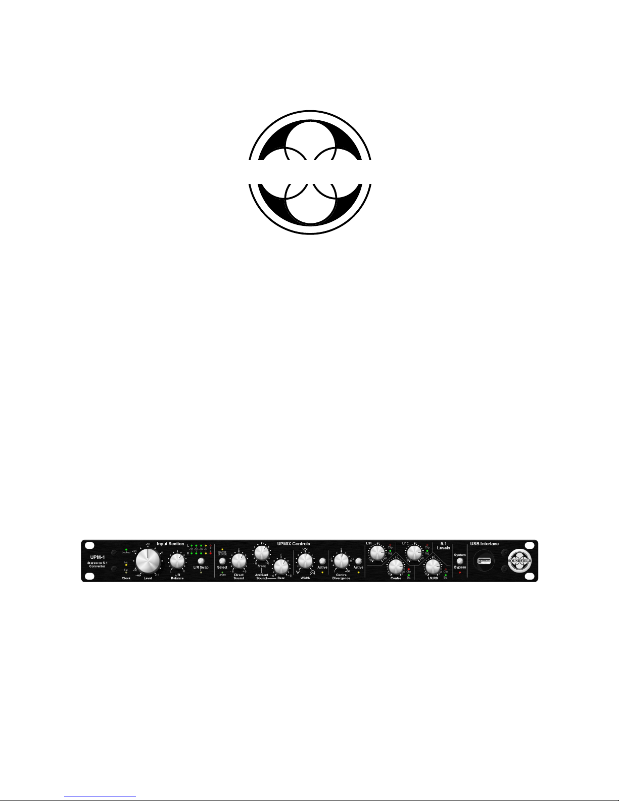
CONTROLS
Input Section
Word Clock INT/EXT
The UPM-1 can be either internally or externally clocked. The on-board sample rate converters
will synchronise the incoming AES-3 streams to either the internal clock or an external word clock
when available. The external wordclock input accepts a 48kHz clock signal only.
Without a valid external wordclock present the unit will be clocked internally, in this case the
amber INT LED will be illuminated. When a valid 48kHz external clock is present this will be
automatically detected and the unit will switch over to the external clock, illuminating the amber
EXT LED.
Locked Status LED
The Locked LED shows the status of the two digital AES-3 inputs. When both inputs are locked
and functioning correctly the green LED will be illuminated, when one of the two inputs is
unlocked the LED will flash on and off, when neither input is locked the LED will not be
illuminated. The digital inputs will accept and lock to any incoming sample rate in the range of
32kHz to 192kHz.
Gain
This control adjusts the input level of the incoming stereo signal and is variable from full
attenuation to a gain of +10dB. Normally this control should be used at or close to its 0dB
position. Two 5-segment bargraph level meters are provided to display the levels of the stereo
input signals.
L/R Balance
The L/R Balance trim allows the user to alter the Left/Right balance of the incoming stereo signal.
Since the 5.1 output of the UPM-1 is entirely based on the stereo input signal it is important to
make sure that the stereo signal image is correctly balanced before upmixing it to 5.1.
L/R Swap
The L/R Swap button allows the user to swap the Left and Right input signals before upmixing to
5.1. An amber status LED indicates when this mode is selected.
Controls
SoundField UPM-1 User Guide

Page 8Controls
Upmix/Matrix Decode Select
The UPM-1 has two modes of operation, Upmix and Matrix Decode - the mode of choice can be
selected by pressing the Upmix/Matrix Decode select button. A green status LED confirms that
Upmix mode is selected and an amber status LED indicates Matrix Decode mode is active.
• Upmix Mode
Upmix mode should be selected when processing standard non-matrix encoded stereo material. In
Upmix mode the UPM-1 sends only ambient sounds to the rear surround channels. The only
exception to this is when the Width control is enabled to the point where a ‘wrap around’ effect is
created by feeding varying degrees of front direct sound to the rear channels.
• Matrix Decode Mode
Matrix Decode mode should be selected when processing matrix encoded stereo material (Dolby®
Pro Logic® etc) .In this mode the UPM-1 will detect any stereo material that has been matrix
encoded and any direct sound intended by the encoding process for the rear surround channels will
be sent there.
Direct Sound
The Direct Sound control increases or decreases the level of direct sound by + or - 6dB. In most
applications direct sound is only present in the front three channels.
Front Ambient Sound
The Front Ambient Sound control increases or decreases the level of ambient sound in the front
Left and Right channels by + or - 6dB.
Rear Ambient Sound
The Rear Ambient Sound control increases or decreases the level of ambient sound in the rear Left
and Right surround channels by + or - 6dB.
Width
The Width control enables the Direct Sound in the original stereo image to be made wider - at its
most extreme the Direct Sound will be in the rear channels. An ‘active’ button with status LED is
provided for instant A/B comparison.
Upmix Controls
SoundField UPM-1 User Guide
Dolby is a registered trademark of Dolby Laboratories.
Pro Logic is a registered trademark of Dolby Laboratories.
SoundField UPM-1 User Guide
Page 9Controls
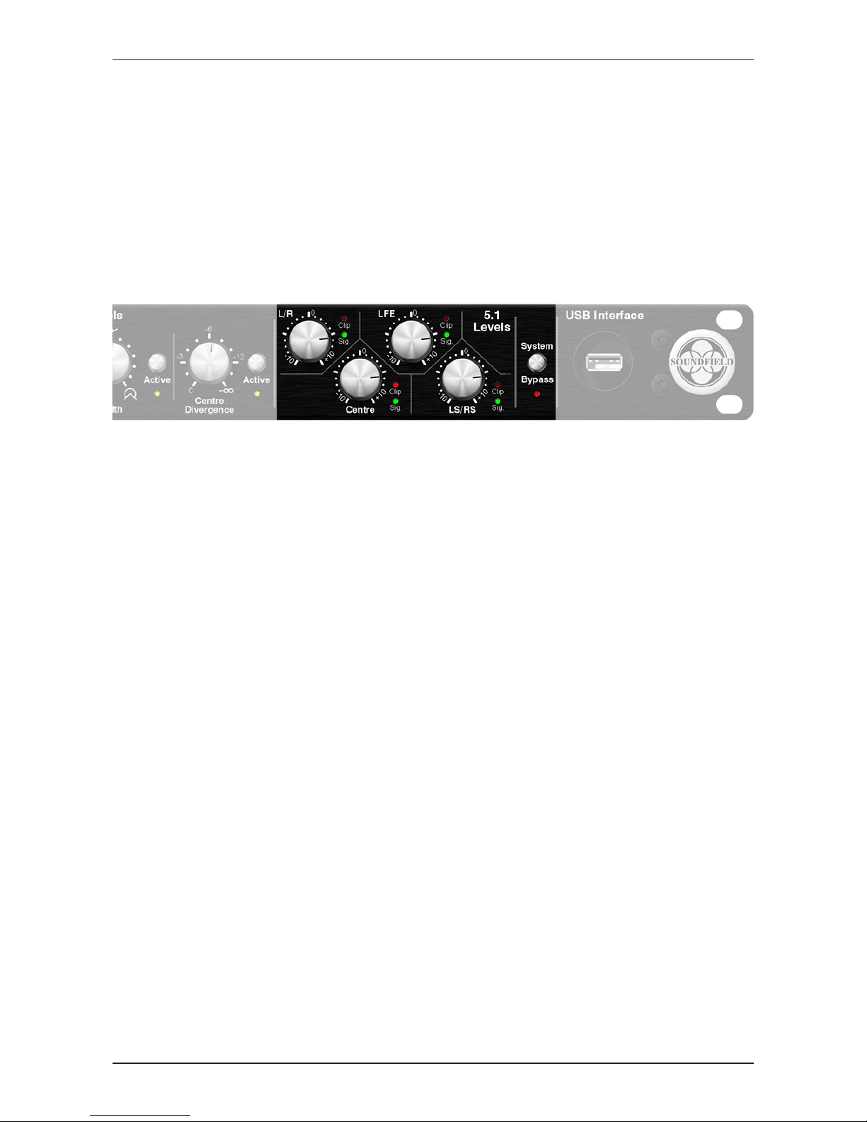
Although in many broadcast situations the UPM-1’s 5.1 outputs will be inserted into the digital
mixing console and operated on faders the following front panel level controls are provided:
L/R
The L/R output control simultaneously increases or decreases the level of both the front Left/Right
channels by + or - 10dB. A green ‘signal present’ and red clip LED are provided to display output
levels.
Centre
The Centre output control increases the level of the Centre channel by + or - 10dB. A green ‘signal
present’ and red clip LED are provided to display the output level.
LFE
The LFE output control increases the level of the LFE channel by + or - 10dB. A green ‘signal
present’ and red clip LED are provided to display the output level.
LS/RS
The LS/RS output control simultaneously increases the level of both the rear LS/RS channels by +
or - 10dB. A green ‘signal present’ and red clip LED are provided to display output levels.
System Bypass
The system bypass button when enabled switches the output back to the original stereo for direct
comparison between the original stereo and the created 5.1.
USB
A front panel USB connection is provided to accommodate future software updates.
5.1 Output Levels
Centre Divergence
The Centre Divergence control takes the centre channel and diverges it to front Left and Right by
the amount set on the control. When no divergence is set all mono material will appear exclusively
in the centre channel (hard centre). When divergence is set to full, all mono material will be sent
to the front Left and Right channels equally and the centre channel will be muted (phantom
centre). Any other divergence setting will create a mix between hard and phantom centre.
Page 10Controls
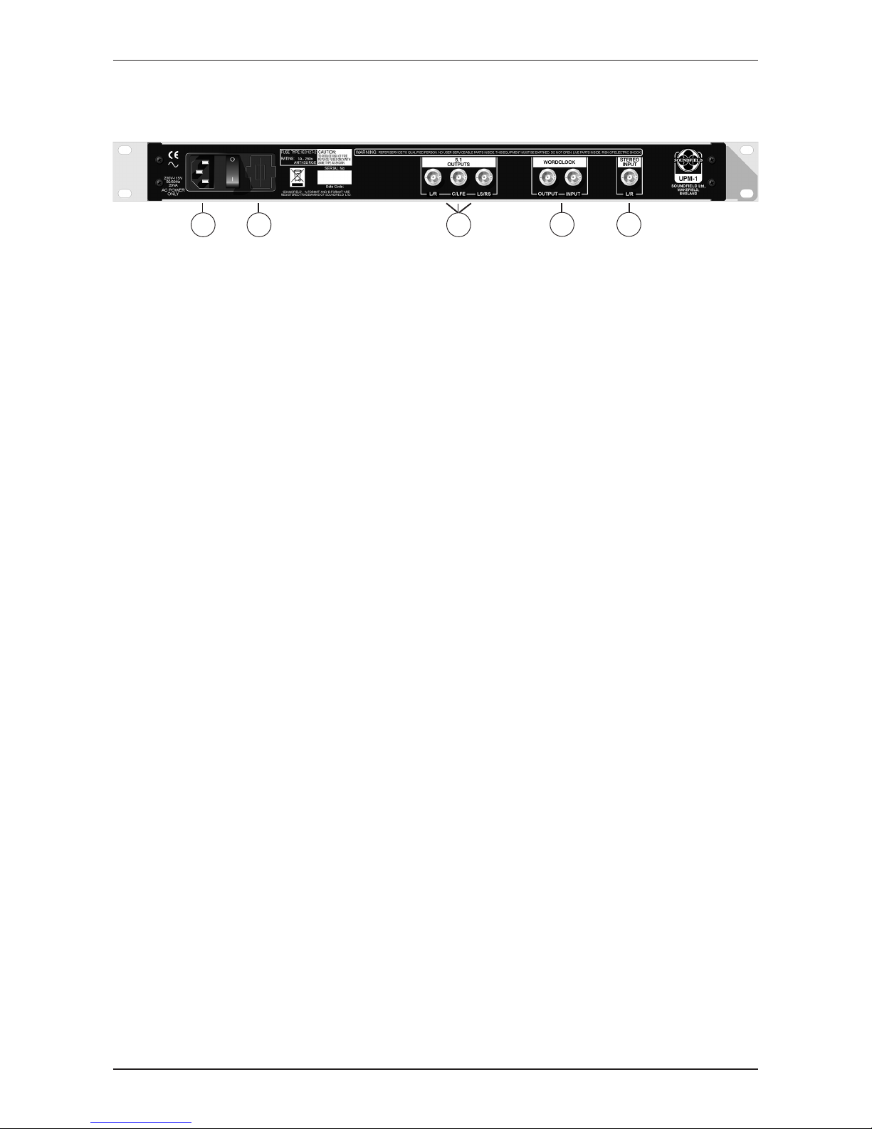
REAR PANEL
1 2 54
3
1. MAINS POWER - ON/OFF mains power switch / IEC mains power inlet
2. FUSE HOLDER - Fuse type IEC127-2 (1A - 250V anti-surge)
3. DIGITAL 5.1 SURROUND OUTPUTS - 75Ω Coax (AES3id) - BNC connectors
4. WORD CLOCK INPUT/OUTPUT - BNC 75Ω, 48kHz only
5. DIGITAL STEREO INPUT - 75Ω Coax (AES3id) - BNC connector
SoundField UPM-1 User Guide

Page 11
AUDIO SPECIFICATION
Digital Input 75Ω Coax (AES3id)
Supported Input Sample Rates 32kHz - 192kHz
Supported Input Bit Rates 16 & 24 bit
Sample Rate Converter AD1896 (128dB SNR)
Digital Outputs 75Ω Coax (AES3id)
Output Sample Rate 48kHz
Output Bit Rate 24 bit
Bandwidth 20Hz - 24kHz
Audio Specification
AC Input 100V - 240V AC 50/60Hz
Power Consumption <20W
Fuse Rating IEC127-2 (1A - 250V anti-surge)
Case Size 482mm (w) x 44mm (h) x 295mm (d)
Weight 2.5 KGS
MAINS REQUIREMENTS
SoundField UPM-1 User Guide

Page 12
WARRANTY
Limited Liability
SOUNDFIELD LTD., HEREIN AFTER KNOWN AS THE MANUFACTURER, GUARANTEES
THIS EQUIPMENT FROM DEFECTS IN MATERIAL AND WORKMANSHIP UNDER
NORMAL USE AND SERVICE FOR A PERIOD OF ONE YEAR. THIS GUARANTEE
EXTENDS TO THE ORIGINAL PURCHASER ONLY AND DOES NOT APPLY TO FUSES OR
ANY PRODUCT OR PARTS SUBJECTED TO MISUSE, NEGLECT, ACCIDENT OR
ABNORMAL CONDITIONS OF OPERATION. THE GUARANTEE BEGINS ON THE DATE
OF DELIVERY TO THE ACTUAL PURCHASER OR TO HIS AUTHORISED AGENT OR
CARRIER. IN THE EVENT OF FAILURE OF A PRODUCT COVERED BY THIS
GUARANTEE, THE MANUFACTURER OR THEIR CERTIFIED REPRESENTATIVES WILL
REPAIR AND CALIBRATE EQUIPMENT RETURNED PREPAID TO AN AUTHORISED
SERVICE FACILITY WITHIN ONE YEAR OF THE ORIGINAL PURCHASE AND
PROVIDED THAT THE GUARANTORS EXAMINATION DISCLOSES TO ITS
SATISFACTION THAT THE PRODUCT WAS DEFECTIVE, EQUIPMENT UNDER THIS
GUARANTEE WILL BE REPAIRED OR REPLACED WITHOUT CHARGE. ANY FAULT
THAT HAS BEEN CAUSED BY MISUSE, NEGLECT, ACCIDENT, ACT OF GOD, WAR OR
CIVIL INSURRECTION; ALTERATION OR REPAIR BY UNAUTHORISED PERSONAL;
OPERATION FROM AN INCORRECT POWER SOURCE OR ABNORMAL CONDITIONS OF
OPERATION, WILL NOT FALL UNDER THIS GUARANTEE. HOWEVER, AN ESTIMATE
OF THE COST OF THE REPAIR WORK WILL BE SUBMITTED BEFORE WORK IS
STARTED. THE MANUFACTURER SHALL NOT BE RESPONSIBLE FOR ANY LOSS OR
DAMAGE, DIRECT OR CONSEQUENTIAL, RESULTING FROM MACHINE FAILURE OR
THE INABILITY OF THE PRODUCT TO PERFORM. THE MANUFACTURER SHALL NOT
BE RESPONSIBLE FOR ANY DAMAGE OR LOSS DURING SHIPMENT TO AND FROM
THE FACTORY OR ITS DESIGNATED SERVICE FACILITY. THIS GUARANTEE IS IN LIEU
OF ALL OTHER GUARANTEES, EXPRESSED OR IMPLIED, AND OF ANY OTHER
LIABILITIES ON THE MANUFACTURERS PART. THE MANUFACTURER DOES NOT
AUTHORISE ANYONE TO MAKE ANY GUARANTEE OR ASSUME ANY LIABILITY NOT
STRICTLY IN ACCORDANCE WITH THE ABOVE. THE MANUFACTURER RESERVES
THE RIGHT TO MAKE CHANGES OR IMPROVEMENT IN THE DESIGN AND
CONSTRUCTION OF THIS UNIT WITHOUT OBLIGATION TO MAKE SUCH CHANGES
OR IMPROVEMENTS IN THE PURCHASER’S UNIT. ANY DISPUTE ARISING FROM THIS
WARRANTY SHALL BE SUBJECT TO THE LAWS OF ENGLAND.
What to do if a fault is found
If a fault develops in the unit, notify SoundField Ltd. or their nearest service facility giving full
details of the difficulty. On receipt of this information, service or shipping instructions will be
forwarded to you. No equipment should be returned under the warranty without prior consent from
SoundField Ltd. or their authorised representative.
Warranty
SoundField UPM-1 User Guide

Page 13
SHIPPING AND QUALITY ASSURANCE
Authorised returns should be prepaid and must be insured. All SoundField products are packaged
in specially designed containers for the best possible protection. If the unit is returned the original
container should be used. If this is not possible, a new container can be obtained from SoundField
Ltd.; please specify the model number when requesting a new container. If the specially designed
container is not used ensure that a suitable rigid container of adequate size is used, wrap the
instrument in paper and surround it with a good thickness of shock absorbing material.
Claim for damage during transit
The instrument should be thoroughly inspected immediately upon delivery to the purchaser. If the
instrument is damaged in any way a claim should be filed with the carrier immediately. A
quotation to repair shipment damage can be obtained from SoundField Ltd or their certified
representative. Final claims and negotiations with the carrier must be completed by the customer.
Applications problems
SoundField Ltd. will be happy to answer any applications questions to enhance your use of this
equipment. Please address all correspondence to:
SoundField Ltd.
Charlotte Street Business Centre
Charlotte Street
Wakefield
West Yorkshire
WF1 1UH
ENGLAND
Tel: +44 (0) 1924 201089
Fax: +44 (0) 1924 290460
email: [email protected]
www.soundfield.com
Quality Assurance and Service Policy
Over the years SoundField products have gained an enviable reputation for their quality of design,
performance and reliability, however, in the unlikely event that problems are encountered with this
unit, please contact SoundField Service at the appropriate address above or alternatively inform
one of our world wide network of distributors who will be able to assist with any of your queries.
Shipping and Quality Assurance
SoundField UPM-1 User Guide
Table of contents


