Imagine neo adc-3981 User manual

Delivering the Moment
Installaon and Operaon Manual
Neo® ADC-3981
Analog-to-Digital Converter
Edion B
175-000071-00

Publicaon Informaon
© 2014 Imagine Communicaons Corp. Proprietary and Condenal.
Imagine Communicaons considers this document and its contents to be proprietary and condenal. Except for
making a reasonable number of copies for your own internal use, you may not reproduce this publicaon, or any part
thereof, in any form, by any method, for any purpose, or in any language other than English without the wrien consent
of Imagine Communicaons. All others uses are illegal.
This publicaon is designed to assist in the use of the product as it exists on the date of publicaon of this manual, and
may not reect the product at the current me or an unknown me in the future. This publicaon does not in any way
warrant descripon accuracy or guarantee the use for the product to which it refers. Imagine Communicaons reserves
the right, without noce to make such changes in equipment, design, specicaons, components, or documentaon as
progress may warrant to improve the performance of the product.
Trademarks
6800+™, ADC™, CCS Navigator™, Channel ONE™, ChannelView™, ClipSync™, Delay™, D Series™, D Series DSX™, Deliver
the Moment™, Delivering the Moment™, FAME™, Farad™, G8™, G Scribe™, HView™, IconMaster™, IconLogo™, IconSta-
on™, IconKey™, InfoCaster™, InfoCaster Creator™, InfoCaster Manager™, InfoCaster Player™, InstantOnline™, Invenio®,
Live Update™, mCAPTURE™, Magellan™, Magellan CCS Navigator™, Magellan Q SEE™, MulService SDN™, NetPlus™,
NetVX™, NewsForce™, Nexio® G8™, Nexio AMP® ChannelView™, Nexio® Channel ONE™, Nexio® ClipSync™, Nexio®
Delay™, Nexio® Digital Turnaround Processor™, Nexio® Farad™, Nexio® G Scribe™, Nexio® IconKey™, Nexio® IconLogo™,
Nexio® IconMaster™, Nexio® IconStaon™, Nexio® InfoCaster™, Nexio® InfoCaster Creator™, Nexio® InfoCaster Manag-
er™, Nexio® InfoCaster Player™, Nexio® InfoCaster Trac™, Nexio® InstantOnline™, Nexio® mCAPTURE™, Nexio® News-
Force™, Nexio® NXIQ™, Nexio® Playlist™, Nexio® Remote™, Nexio®RTX Net™, Nexio® TitleMoon™, Nexio® TitleOne™,
Nexio® Velocity ESX™, Nexio® Velocity PRX™, Nexio® Velocity XNG™, Nexio® Volt™, OPTO+™, Panacea™, Planum™,
Playlist™, Predator II GRF™, Predator II GX™, Punctuate™, Remote™, RTX Net™, QuiC™, Q SEE™, SD STAR™, Selenio™,
Selenio 6800+™, SelenioNext™, Selenio X50™, Selenio X85™, Selenio X100™, TitleMoon™, TitleOne™, Velocity ESX™,
Velocity PRX™, Velocity XNG™, Versio™, Videotek® SD STAR™, X50™, and X85™ are trademarks of Imagine Communica-
ons or its subsidiaries.
Altude Express®, Connectus®, Enabling PersonalizedTV®, ICE® Broadcast System, ICE Illustrate®, ICE Q® algorithms, ICE-
PAC®, Imagine ICE®, Inscriber®, Inscriber® Connectus®, Invenio®, NEO®, Nexio®, Nexio AMP®, PersonalizedTV®, Router-
Works®, Videotek®, Videotek® ASI STAR®, Videotek® GEN STAR®, and Videotek® HD STAR® are registered trademarks of
Imagine Communicaons or its subsidiaries.
Microso® and Windows® are registered trademarks of Microso Corporaon. HD BNC is a trademark of Amphenol
Corporaon. Some products are manufactured under license from Dolby Laboratories. Dolby and the double D symbol
are registered trademarks of Dolby Laboratories. DTS Neural audio products are manufactured under license from DTS
Licensing Limited. DTS and the Symbol are registered trademarks & the DTS Logos are trademarks of DTS, Inc. © 2008
2010 DTS, Inc. All other trademarks and trade names are the property of their respecve companies.
Contact Informaon
Imagine Communicaons has oce locaons around the world. For locaons and contact informaon see:
hp://www.imaginecommunicaons.com/contact us/
Support Contact Informaon
For support contact informaon see:
▪Support Contacts: hp://www.imaginecommunicaons.com/services/technical support/
▪eCustomer Portal: hp://support.imaginecommunicaons.com
© 2014 Imagine Communicaons Corp. Proprietary and Condenal

Edition B
December 2005
ADC-3981
Analog-to-Digital Converter
Installation and Operation Manual


ADC-3981 Installation and Operation Manual iii
Contents
Trademarks and Copyrights .................................................................... ii
Warranty Information ............................................................................. ii
Preface
Manual Information .............................................................................. vii
Purpose ........................................................................................... vii
Audience ........................................................................................ vii
Revision History ............................................................................ vii
Writing Conventions ..................................................................... viii
Obtaining Leitch Documents .......................................................... ix
Unpacking the Module ........................................................................... ix
Safety Standards and Compliances ..........................................................x
Safety Terms and Symbols ...............................................................x
Restriction on Hazardous Substances (RoHS) Directive ....................... xi
Waste from Electrical and Electronic Equipment (WEEE) Directive .. xii
Chapter 1: Introduction
Overview ..................................................................................................1
Product Description ..................................................................................2
Main Features ...................................................................................2
Front and Back Modules ..........................................................................3
Front Module ....................................................................................3
Back Module .....................................................................................4
Plug-In Adapter .................................................................................5
Signal Flow ..............................................................................................6
Chapter 2: Installation and Removal
Overview ..................................................................................................7
Packing List ..............................................................................................8

iv ADC-3981 Installation and Operation Manual
Contents
Installing ADC-3981 Modules ................................................................ 8
Removing ADC-3981 Modules .............................................................. 8
Setting Jumpers ....................................................................................... 9
Upgrading ADC-3981 Firmware .......................................................... 11
Upgrading the Firmware (Discovery Method) ............................... 11
Upgrading the Firmware (Drag-and-Drop Method) ...................... 13
Correcting a Failed Upgrading Procedure ............................................. 15
Setting the Module to Fail-Safe Loader Mode ............................... 15
Upgrading the Firmware in Fail-Safe Mode .................................. 15
Rebooting the Module .................................................................... 17
Chapter 3: Operation
Overview ............................................................................................... 19
Operation Notes ..................................................................................... 20
Cross-Functional Parameter Changes ................................................... 21
Navigating the Operator and All Lists .................................................. 22
Operator and All List Parameters .......................................................... 23
Setup Parameters ................................................................................... 26
Alarms ................................................................................................... 27
Alarm Synchronization .................................................................. 27
Identifying the Cause of an Alarm ................................................. 27
Enabling or Disabling an Alarm Parameter ................................... 28
Restoring Default Settings ............................................................. 28
State Recovery Parameter Availability ................................................. 28
LEDs and Module Indicators ................................................................ 29
General Information ....................................................................... 29
Card-Edge LED Locations ............................................................. 30
LED Descriptions ........................................................................... 31
Module Indicator Descriptions ....................................................... 32
Chapter 4: Specifications
Overview ............................................................................................... 33
Input ...................................................................................................... 34
Analog Audio (Balanced) .............................................................. 34
External Reference ......................................................................... 34
Output .................................................................................................... 35
Digital Audio .................................................................................. 35
Miscellaneous ........................................................................................ 36
Performance ................................................................................... 36

ADC-3981 Installation and Operation Manual v
Contents
Power Consumption ........................................................................36
Start-Up Time .................................................................................36
Appendix A: Tree-View Navigation
Overview ................................................................................................37
Navigating the Tree View ......................................................................38
Tree View Parameters ............................................................................39
Appendix B: Audio Bit Manipulation
Overview ................................................................................................43
Channel Status Bits ................................................................................44
Validity and User Bits ............................................................................46
Index
Keywords ...............................................................................................47

vi ADC-3981 Installation and Operation Manual
Contents

ADC-3981 Installation and Operation Manual vii
Preface
Manual Information
Purpose
This manual details the features, installation, operation, maintenance,
and specifications of the NEO ADC-3981 Analog-to-Digital Converter.
Audience
This manual is written for engineers, technicians, and operators
responsible for the installation, setup, maintenance, and operation of the
NEO ADC-3981 Analog-to-Digital Converter.
Revision History
Table P-1. Revision History of Manual
Edition Date Revision History
A October 2002 Initial release
B December 2005 Revisions of product codes, parameter and
default modifications, alarm corrections,
and manual template updates

viii ADC-3981 Installation and Operation Manual
Preface
Writing Conventions
This manual adheres to the following writing conventions.
Table P-2. Writing Conventions
Term or Convention Description
Bold Indicates dialog box, property sheet, field,
button, check box, list box, combo box,
menu, submenu, window, list, and
selection names
Italics Indicates email addresses, names of books
and publications, and first instances of new
terms and specialized words that need
emphasis
CAPS Indicates a specific key on the keyboard,
such as ENTER, TAB, CTRL, ALT,
DELETE
Code Indicates variables or command-line
entries, such as a DOS entry or something
you type into a field.
> Indicates the direction of navigation
through a hierarchy of menus and
windows.
hyperlink Indicates a jump to another location within
the electronic document or elsewhere
Internet address Indicates a jump to a Web site or URL
Note
Indicates important information that helps
to avoid and troubleshoot problems

ADC-3981 Installation and Operation Manual ix
Preface
Obtaining Leitch Documents
Installation, navigation, configuration, and setup information is now
included in the NEO FR-3901, FR-3903, and FR-3923 Mounting
Frames Installation and Operation Manual. If your current NEO frame
manual is Edition A, B, C, or D, you will need to download an updated
version from the Leitch Web site to access this information.
Leitch documents can be viewed or downloaded from the Leitch Web
site at www.leitch.com (go to Support>Documentation).
Alternatively, contact your Leitch customer service representative to
request a document.
Unpacking the Module
Before you install and configure NEO modules, follow these steps:
1. Check the equipment for any visible damage that may have
occurred during transit.
2. Confirm that you have received all items listed on the packing list.
3. Remove the anti-static shipping pouch, if present, and all other
packaging material.
4. Retain the original packaging materials for possible reuse.
5. Contact your Leitch sales representative if parts are missing or
damaged.
Keep at least one set of original packaging in the event that a product
needs to be returned for service. If the original package is not available,
you can purchase replacement packaging from Leitch Technology.
Otherwise, you can supply your own packaging as long as it meets the
following criteria:
• The packaging must be able to withstand the product’s weight.
• The product must be held rigid within the packaging.
• There must be at least two inches (five centimeters) of space
between the product and the container.
• The corners of the product must be protected.
If the product is still within the warranty period, Leitch Technology will
return it to you by prepaid shipment after servicing.
x ADC-3981 Installation and Operation Manual
Preface
Safety Standards and Compliances
See the NEO Safety Instructions and Standards Manual to find the
safety standards and compliances for this NEO series product. A safety
manual is shipped with every FR-3901, FR-3903, and FR-3923
Mounting Frames Installation and Operation Manual and can be
downloaded from the Leitch Web site at www.leitch.com. Alternatively,
contact your Leitch customer service representative for a copy of this
safety manual.
Safety Terms and Symbols
This manual uses the following safety terms and symbols. See your
NEO Safety Instructions and Precautions Guide for more information.
Table P-3. Safety Terms and Symbols Used in Manual
WARNING:
Statements identifying conditions or practices that can result in
personal injury or loss of life: High voltage is present. Uninsulated
dangerous voltage within the product’s enclosure may be sufficient
to constitute a risk of electric shock to persons.
CAUTION:
Statements identifying conditions or practices that can result in
damage to the equipment or other property: Important operating
and maintenance (servicing) instructions in the literature
accompanying the product.

ADC-3981 Installation and Operation Manual xi
Preface
Restriction on Hazardous Substances (RoHS)
Directive
Directive 2002/95/EC—commonly known as the European Union (EU)
Restriction on Hazardous Substances (RoHS)—sets limits on the use of
certain substances found in electrical and electronic equipment. The
intent of this legislation is to reduce the amount of hazardous chemicals
that may leach out of landfill sites or otherwise contaminate the
environment during end-of-life recycling. The Directive takes effect on
July 1, 2006, and it refers to the following hazardous substances:
• Lead (Pb)
• Mercury (Hg)
• Cadmium (Cd)
• Hexavalent Chromium (Cr-V1)
• Polybrominated Biphenyls (PBB)
• Polybrominated Diphenyl Ethers (PBDE)
In accordance with this EU Directive, all Leitch Technology products
sold in the European Union will be fully RoHS-compliant and
“lead-free.” (See the Leitch Web site, www.leitch.com, for more
information on dates and deadlines for compliance.) Spare parts
supplied for the repair and upgrade of equipment sold before
July 1, 2006 are exempt from the legislation. Leitch equipment that
complies with the EU directive will be marked with a RoHS-compliant
symbol, as shown in Figure 1.
Figure 1. RoHS Compliance Symbol

xii ADC-3981 Installation and Operation Manual
Preface
Waste from Electrical and Electronic
Equipment (WEEE) Directive
The European Union (EU) Directive 2002/96/EC on Waste from
Electrical and Electronic Equipment (WEEE) deals with the collection,
treatment, recovery, and recycling of electrical and electronic waste
products. The objective of the WEEE Directive is to assign the
responsibility for the disposal of associated hazardous waste to either
the producers or users of these products. Effective August 13, 2005,
producers or users will be required to recycle electrical and electronic
equipment at the end of its useful life, and must not dispose of the
equipment in landfills or by using other unapproved methods. (Some
EU member states may have different deadlines.)
In accordance with this EU Directive, Leitch Technology International,
Inc. and other companies selling electric or electronic devices in the
EU will affix labels indicating that such products must be properly
recycled. (See the Leitch Web site, www.leitch.com, for more
information on dates and deadlines for compliance.) Contact your local
Leitch sales representative for information on returning these products
for recycling. Leitch equipment that complies with the EU directive will
be marked with a WEEE-compliant symbol, as shown in Figure 2.
Figure 2. WEEE Compliance Symbol

ADC-3981 Installation and Operation Manual 1
Chapter 1: Introduction
Chapter 1
Introduction
Overview
The ADC-3981 Analog-to-Digital Converter are designed for use in
NEO™ 1RU and 3RU rack-mounted frames.
This chapter covers the following topics:
•“Product Description” on page 2
•“Front and Back Modules” on page 3
•“Signal Flow” on page 6
See the FR-3901, FR-3903, and FR-3923 Installation and Operation
Manual for information about NEO frames. The frame manual includes
information about these items:
• General information about module unpacking, installation,
removal, navigation, configuration, and setup
• Card-edge screen savers
• State recovery parameters
•Fanmodules
• Resource modules
• Alarm interconnect modules
• Power supplies
• Servicing instructions
Note
Installation, navigation,
configuration, and setup
information for NEO modules is
now included in the NEO
FR-3901, FR-3903, and
FR-3923 Mounting Frames
Installation and Operation
Manual. If your current NEO
frame manual is Edition A, B,
C, or D, you will need to
download an updated version
from the Leitch Web site
(www.leitch.com) to access this
information.

2 ADC-3981 Installation and Operation Manual
Chapter 1: Introduction
Product Description
The ADC-3981 consists of two independent audio processing units,
capable of handling two pairs (four channels) of analog audio inputs,
and two pairs of digital audio outputs. This module has full audio
processing capabilities, including gain, channel swap, invert, and delay
control. The ADC-3981 also has four independent tone generators.
Main Features
These are the main features of the ADC-3981 module:
• Two independent analog-to-digital conversion channels
• 32/44.1/48/96 kHz capability
• Selectable 16-, 20-, and 24-bit analog-to-digital conversion
• Internal audio processing amplifier
• Multiple tone generators (750 Hz, 1.5 kHz, 3 kHz, and 6 kHz)
• Four balanced analog audio inputs
• Peak/Silence/Tone indication
• Selectable delay for each channel
• Two balanced and two unbalanced AES audio outputs
• External video and DARS reference input
• Capability for control via card-edge, local control panels, remote
control panels, and GUI applications (3901RES-E resource module
is required for Ethernet use)
ADC-3981 Installation and Operation Manual 3
Chapter 1: Introduction
Front and Back Modules
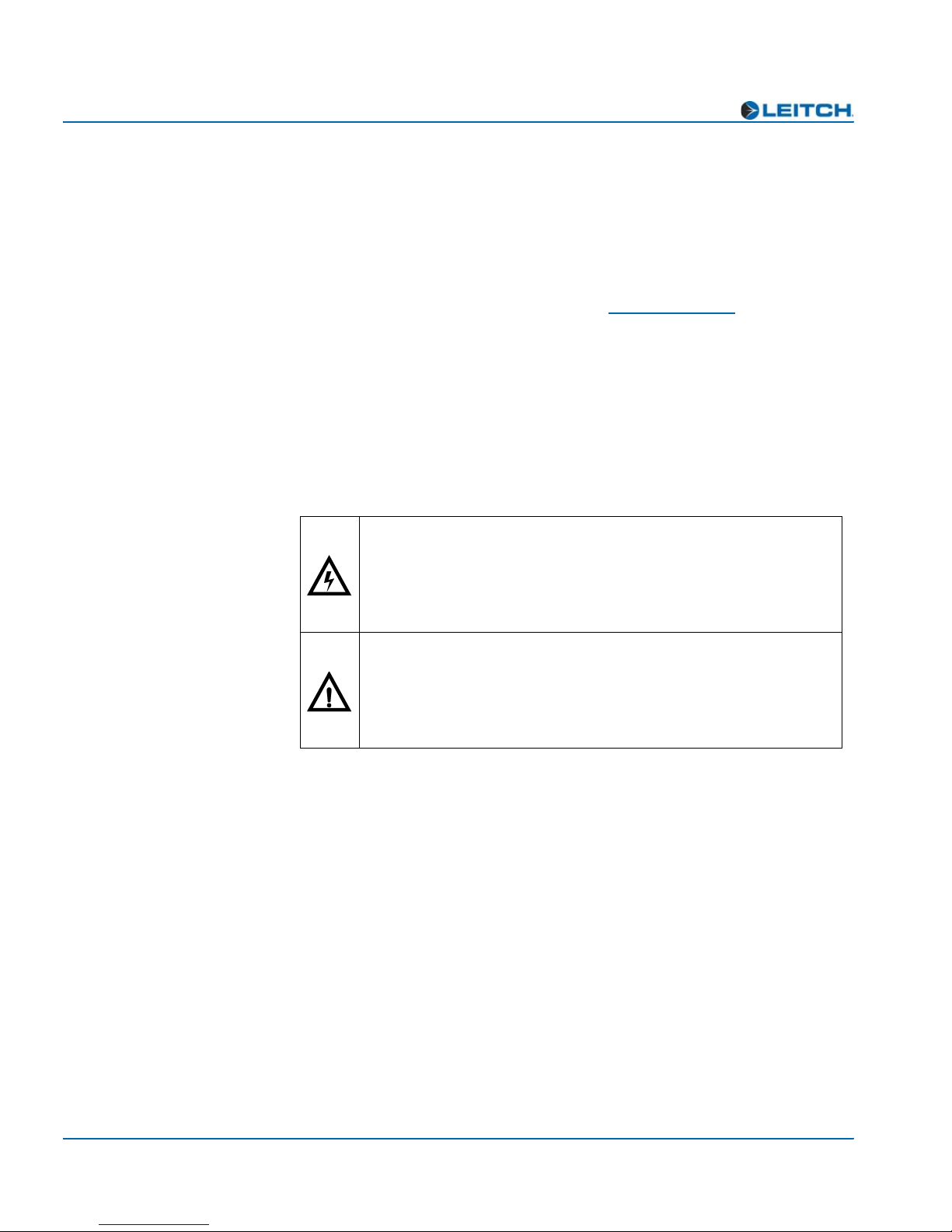
Front Module
NEO front modules are designated by the suffix “-FM.” For example,
the front module of the ADC-3981 is the “ADC-3981-FM.” Figure 1-1
illustrates the position of the LEDs and card-edge controls on the
ADC-3981-FM front module.
Figure 1-1. ADC-3981-FM Front Module
Top view
Nav+/Nav- switch
(up/down) Extractor handle
Escape button
Module
Status
Minor
Alarm
Major
Alarm Power
SW1
Nav +
Nav -
Enter
Esc
MAJOR
ALARM
MINOR
ALARM
POWER MODULE
STATUS
Module indicators
Remote/Local
switch
LEDs
Enter button
REM LOC
Sync/Delay
Genlock Lock
Genlock Present
Genlock Standard
DARS Present
DARS Ref Error
AES1 Present
Ch1 Peak
Ch1 Mute
Ch1 Tone
AES2 Present
Ch2 Peak
Ch2 Mute
Ch2 Tone
Card extractor
Remote/Local switch
(hidden behind extractor)
Front view
64 X 16 VFD
submodule
Visible display area
Nav+/Nav- switch
(up/down)
Escape button
Enter button
4 ADC-3981 Installation and Operation Manual
Chapter 1: Introduction
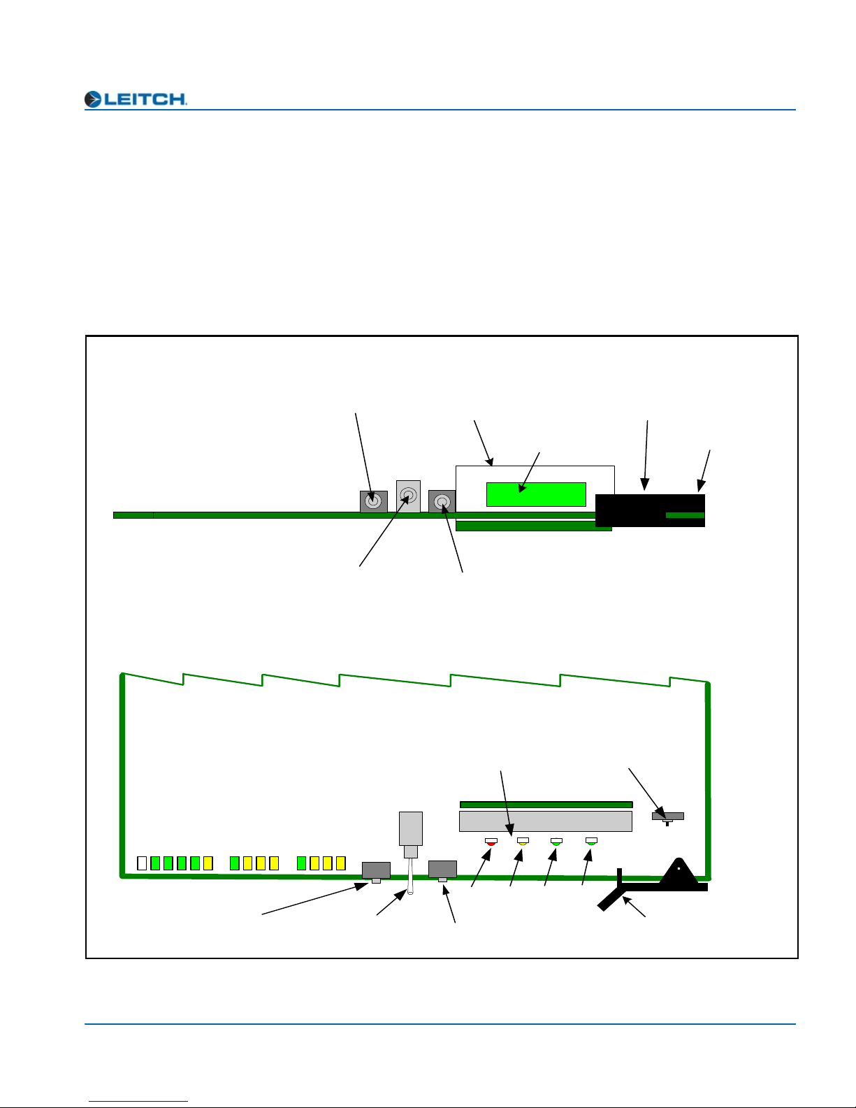
Back Module
In the NEO frame, back modules are placed directly behind the front
modules. Back modules are designated by the suffix “-BM”. For
example, the back module of the ADC-3981 is the “ADC-3981-BM.”
Figure 1-2 shows the ADC-3981-BM back module.
Figure 1-2. ADC-3981-BM Back Module
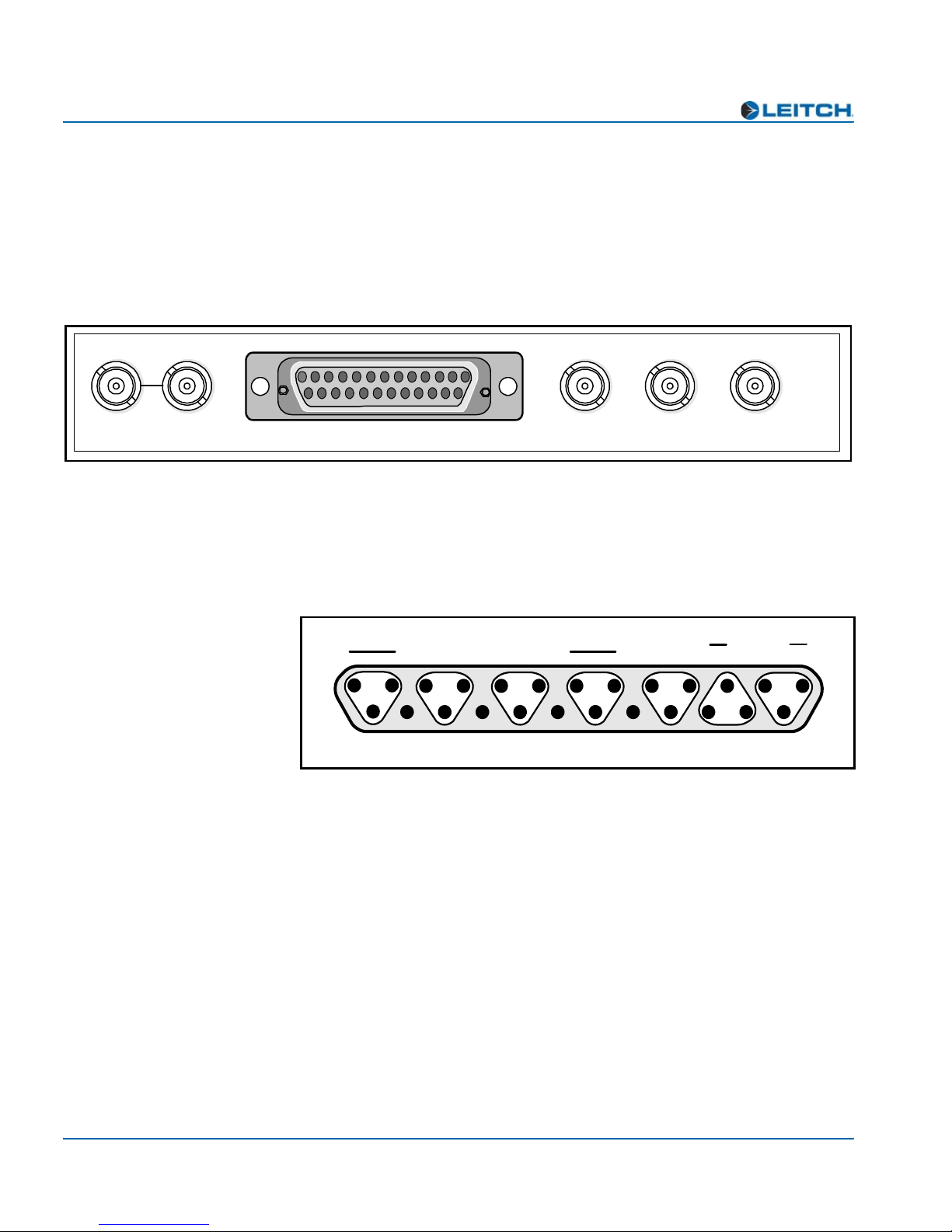
Back Module Pinouts
Figure 1-3 shows the pinouts for the Analog Audio In, DARS In, and
Balanced AES Out connectors on the ADC-3981-BM back module.
Figure 1-3. ADC-3981-BM Back Module Balanced Pinouts
ADC-3981
ANALOG AUDIO IN DARS BALANCED AES INPUT
GENLOCK
INPUT/LOOP
UNBALANCED AES OUT
IN DARS CHANNEL 1 CHANNEL 2
1
25
13
14
AG
G
-+
G
-+
G
-+
DARS in
Channel
1A
Channel
2A
Channel
1B
Channel
2B Channel 2 Channel 1
Balanced analog audio in
Balanced
AES out
AG AG
AG
-
+
AG
-
+
AG
AG
-
+
AG
-
+

ADC-3981 Installation and Operation Manual 5
Chapter 1: Introduction
Plug-In Adapter
The ADC-3981-BM back module is shipped with a detachable plug-in
adapter (AIB-25-MF) for connecting twisted-pair audio cables directly
to the back module. Figure 1-4 identifies the screw terminals for the
AIB-25-MF plug-in adapter.
Figure 1-4. Screw Terminals for the AIB-25-MF Plug-in Adapter
G
+ –
G
Ch 2B
G
+ –
G
G
G
Ch 2A
Ch 1B Ch 1A
balanced balanced
G
+ –
G
– +
balanced
Analog
grounds
Digital
grounds
G
+ –
G
+ –
G
+ –
GG
Digital audio output and DARS input (3rd row)
AES 1 AES 2 DARS
Analog audio input (1st two rows)

6 ADC-3981 Installation and Operation Manual
Chapter 1: Introduction
Signal Flow
Figure 1-5 illustrates the signal flow of the ADC-3981.
Figure 1-5. ADC-3981 Functional Block Diagram
2 AES (75 )
Ω
CPU
4 analog audio or
2x2 analog audio
A-D
2 AES (110 )
Ω
Composite Analog
Reference
(NTSC or PAL)
DARS
Table of contents
Other Imagine Media Converter manuals


Popular Media Converter manuals by other brands


Monoprice
Monoprice 21828 user manual

Transition Networks
Transition Networks C4TEF1011-110 user guide

Akai
Akai ASB15I user manual

OT Systems
OT Systems FT110DBE Series Installation and operation manual

Cypress
Cypress HTCP-255DN Operation manual

Shenyang Guangcheng Technology
Shenyang Guangcheng Technology GCAN-208 user manual


