Baudcom BD-OP-MUX32 User manual

Model: BD-OP-MUX32
32PCM+4GE+4E1+Console
Voice Fiber Optical Multiplexer
User’s Manual
SHANGHAI BAUDCOM COMMUNICATION DEVICE CO.,LTD
Website: http://www.baudcom.com.cn
Email: info@baudcom.com.cn
Tel: +86 21 37709251

32PCM voice multiplexer user manual
1
目录
1. OVERVIEW ............................................................................................................................................................ 2
2. FEATURES ............................................................................................................................................................. 2
3. PARAMETERS ...................................................................................................................................................... 3
4. PANEL .................................................................................................................................................................... 6
5. INDICATOR LED .................................................................................................................................................. 7
6. DIP SWITCH ......................................................................................................................................................... 8
7. FIBER PORTS ........................................................................................................................................................ 9
8. E1 PORTS .............................................................................................................................................................. 9
9. VOICE PORTS ....................................................................................................................................................... 9
10. ETHERNET PORTS ........................................................................................................................................... 11
11. CONSOLE PORT ................................................................................................................... 错误!未定义书签。
12. AUX PORTS(OPTIONAL) ...........................................................................................................................29
13. POWER ...............................................................................................................................................................30
14. AFTER SALES ....................................................................................................................................................31
15. COMPANY STATEMENT .................................................................................................................................31

32PCM voice multiplexer user manual
2
Dear users:
Thank you for using Baudcom product. In order to make your work smoothly,
we give you some advice. Before you connect and operate the product, you should
make sure to read this manual carefully and pay more attention to the notices.
1. Overview
The 32channel POTs fiber multiplexer is a kind of developed point to point
transmission equipment based on Baudcom PDH fiber transmission the special-use
VLSI. This device provides 32Channel telephone 1-4Channel E1 interface, 4Channel
10/100/1000M Ethernet interface (Line Speed 1000M, Physical isolation) and 1
expansion interface. 4Channel Ethernet interface is switch interface, can support
VLAN. 1 expansion interface can be used as the transmission channel of
RS232/RS485/RS422 asynchronous data, voice signal, 2/4 Line E&M audio signal,
switch signal, Ethernet signal (Bandwidth 2M). It has alarm function. The working is
reliable, stable, and low power consumption, high integration, small size, ease of
installation and maintenance.
2. Features
Based on self -copyright IC
The machine is single PCB design
Can monitor the remote alarm status
E1 interface comply with G.703, adopts digital clock recovery and smooth
phase-lock technology
Provide 2 expansion interfaces (AUX1/2 ), you can extend 1-4Channel

32PCM voice multiplexer user manual
3
asynchronous data, such as RS232/RS485/RS422/Manchester code; 1-8Channel
switch, two/four line audio and so on
1-30Channel voice access, supports caller ID feature and reverse polarity billing
functions
Support various sites mutual number allocation function
Voice port supports FXO and FXS port, EM2/4 audio interface, FXO port docking
with program-controlled switchboard, FXS port connected to the user's telephone
Desktop device supports independent SNMP network management and optical
multiplexer network management cascade (optional)
Have LED when the device is power-off or E1 line is broken or lose signal
Can monitor the temperature and voltage (network management platform)
Can monitor the remote equipment temperature and voltage (network
management platform)
AC 100V-265V, DC-48V can be optional
3. Parameters
Fiber
Multi-mode Fiber
50/125um, 62.5/125um,
Maximum transmission distance: 5KM@62.5/125um single mode fiber,
attenuation (3dbm/km)
Wave Length: 820nm
Transmitting power: -12dBm (Min) ~-9dBm (Max)

32PCM voice multiplexer user manual
4
Receiver sensitivity: -28dBm (Min)
Link budget: 16dBm
Single-mode Fiber
8/125um, 9/125um
Maximum transmission distance: 40Km
Transmission distance: 40KM@9/125um single mode fiber, attenuation
(0.35dbm/km)
Wave Length: 1310nm
Transmitting power: -9dBm (Min) ~-8dBm (Max)
Receiver sensitivity: -27dBm (Min)
Link budget: 18dBm
FXS Phone Interface
Ring voltage: 75V
Ring frequency: 25HZ
Two-line Impedance: 600 Ohm (pick up)
Return loss: 40 dB
FXO Switch Interface
Ring detect voltage: 35V
Ring detection frequency: 17HZ-60HZ
Two-line Impedance: 600 Ohm (pick up)
Return loss: 40 dB
E1 Interface

32PCM voice multiplexer user manual
5
Interface Standard: comply with protocol G.703;
Interface Rate: 2048Kbps±50ppm;
Interface Code: HDB3;
E1 Impedance: 75Ω (unbalance), 120Ω (balance);
Jitter tolerance: In accord with protocol G.742 and G.823
Allowed Attenuation: 0~6dBm
Ethernet interface (10/100/1000M)
Interface rate: 10/100/1000Mbps, half/full duplex auto-negotiation
Interface Standard: Compatible with IEEE 802.3, IEEE 802.1Q (VLAN)
MAC Address Capability: 4096
Connector: RJ45, support Auto-MDIX
Power
Power supply: AC100V ~ 260V;DC –48V
Power consumption: ≤7W
Dimension
19 inch 1U: 483(L)X183(W)X44(H)mm
Working Environment
Working temperature: -10°C ~ 60°C
Working Humidity: 5%~95 % (no condensation)
Storage temperature: -40°C ~ +85°C
Storage Humidity: 5%~95 % (no condensation)

32PCM voice multiplexer user manual
6
4. Panels
Figure 1: front panel function distribution diagram
Figure 2: function distribution diagram of 75 Euro E1 rear panel
Figure 3: function distribution diagram of 120 Euro E1 rear panel

32PCM voice multiplexer user manual
7
5. INDICATOR LED
NAME COLOR STATUS DESCRIPTION
LPWR Green
ON Device power is ON
OFF Device power is OFF
RPWR Green
ON The remote device power is ON
OFF The remote device power is OFF
F1 Green
ON Fiber 1 connected
F2 Green
ON Fiber 2 connected
LOS1-8 Red
ON Correspoinding1~8 channel E1 signal loss
OFF Correspoinding1~8 channel E1 signal normal
P1-32 Green
ON Corresponding 1-32Channel voice is busy or
picking up
ON/Flash
Caller ID display
OFF Corresponding 1-32Channel voice is not
busy or no caller
RPWR Description:
If signal indicator light OLOS is ON, there are two cases. One case is that the
transmission line is broken; the other case is that the remote equipment is power off.
As follows:
OLOS ON, RPWR OFF: Remote device is power off;
OLOS ON, RPWR ON: Fiber line is broken;
OLOS OFF, RPWR ON: Normal Work

32PCM voice multiplexer user manual
8
6. DIP SWITCH
DIP1 (1-4):
DIP1-1
DIP1-2
DIP1-3
DIP1-4
COMMAND REMOTE E1
LOOP BACK
OFF OFF OFF OFF All E1 not loop-back(Default)
ON ON ON OFF Remote NO.8 E1 Loop-Back
OFF OFF OFF ON Remote NO.7 E1 Loop-Back
ON OFF OFF ON Remote NO.6 E1 Loop-Back
OFF ON OFF ON Remote NO.5 E1 Loop-Back
ON ON OFF ON Remote NO.4 E1 Loop-Back
OFF OFF ON ON Remote NO.3 E1 Loop-Back
ON OFF ON ON Remote NO.2 E1 Loop-Back
OFF ON ON ON Remote NO.1 E1 Loop-Back
ON ON ON ON All Remote E1 Loop-Back
DIP1:5-8:
DIP1 STATUS FUNCTION
5(VLAN)
OFF Not open VLAN isolation function(Default)
ON Open VLAN isolated function (valid only
when choose2to 4 Ethernet interfaces)
6(MUTE) OFF Alarm sound is on(Default)
ON Alarm sound is off
7(LRS) OFF
Indicator light indicates local device work
condition(Default)
ON Indicator light indicates the remote device
8(FLOP) OFF Not open fiber loopback(Default)
ON Open fiber loopback
32PCM voice multiplexer user manual
9
7. Fiber ports
Physical Interface: FC/SC (Optional), single-fiber and dual-fiber (Optional).
Dual-Fiber: TX-Transmit RX-Receive
Single-Fiber: Transmit and Receive (Note: 1310nm and 1550nm
device used in pair)
Note: the two fiber ports are used for 1+1 redundant.
8. E1 Interfaces
There are 4 RJ45 ports for 8E1, one RJ45 for 2E1, when E1 is 75Ω,configure
one cable for 1RJ 45 converting to 4bnc.
75Ω-BNC Socket
PIN defined as follows:
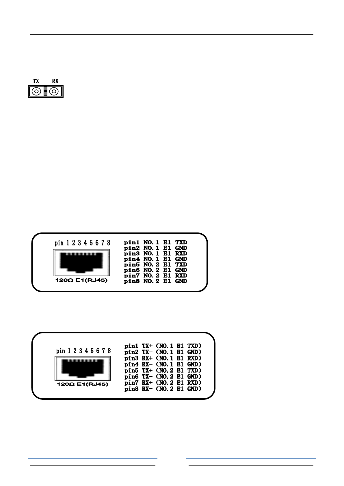
120Ω-RJ45 Socket
PIN defined as follows:
32PCM voice multiplexer user manual
10
9. Telephone ports
There are 32 RJ45 connectors on back panel, support 1-32 analog line telephones
access. The device supports two interfaces: FXO and FXS. If this device is built-in
FXO module, the interface is FXO interface, you can insert the phone line that that
through switch into FXO interface. If this device is built-in FXS module, the interface
is FXS interface, you can insert it into telephone directly.
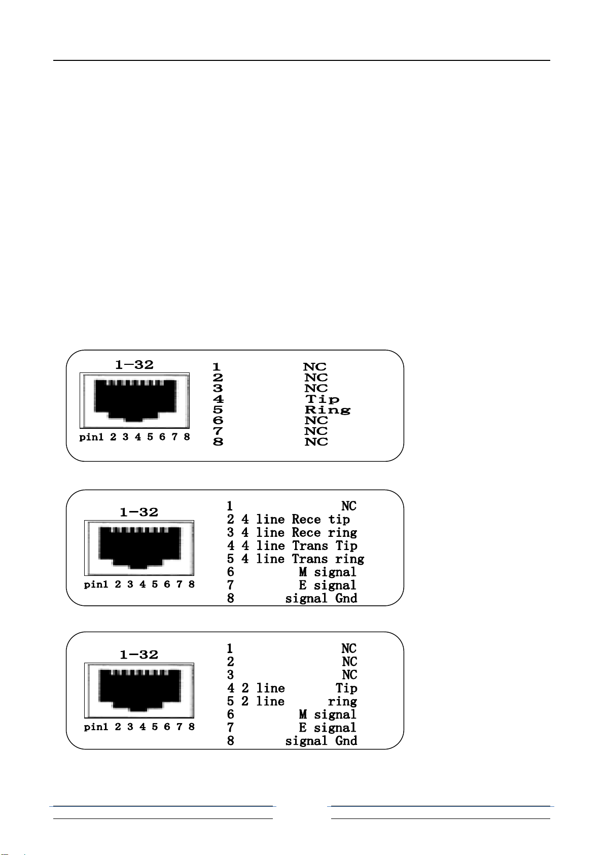
One RJ45 connector can support 1Channel analog telephone access (telephone
interface), PIN defined as follows:
FXO/(FXS) Pin define:
EM 4 Pin define:
EM 2 Pin define:
32PCM voice multiplexer user manual
11
10. Ethernet ports
4Channel Physical isolation Ethernet can be optional. Support 10/100/1000M,
half/full duplex auto- negotiation and AUTO-MDIX (crossed line and straightly
connected line self-adaptable)
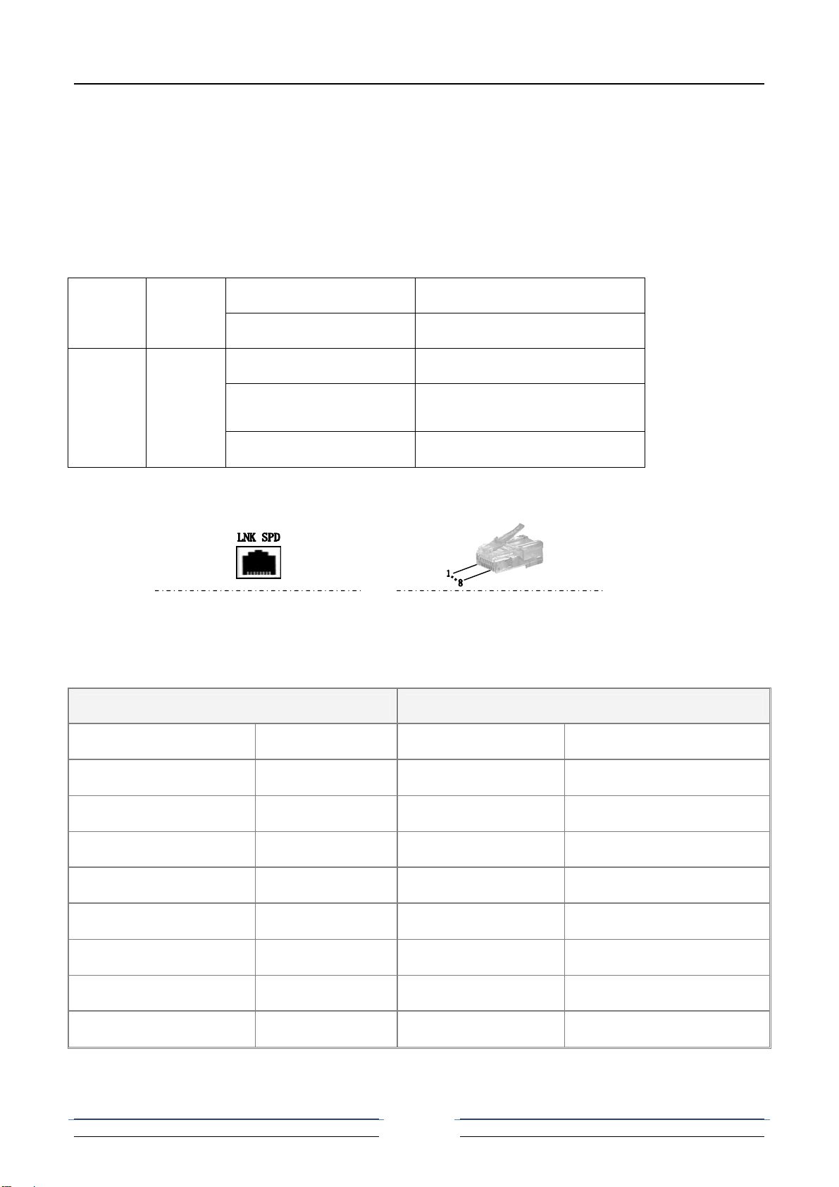
LNK Green ON Ethernet is connected
OFF Ethernet is not connected
SPD Green
Blink 3 Times Ethernet rate is 1000M
Blink 2 Times Ethernet rate is 100M
Blink 1 Times Ethernet rate is 10M
RJ45 Connector and Crystal head PIN order as follows:
Represent 10/100/1000M Ethernet Interface Crystal head PIN order
Straightly connected line order
A end Crystal head PIN B end crystal head PIN
Twisted Pair Color PIN order PIN order Twisted Pair Color
White and Orange 1 1 White and Orange
Orange 2 2 Orange
White and Green 3 3 White and Green
Blue 4 4 Blue
White and Blue 5 5 White and Blue
Green 6 6 Green
White and Brown 7 7 White and Brown
Brown 8 8 Brown
Crossed line order

32PCM voice multiplexer user manual
12
A end Crystal head PIN B end crystal head PIN
Twisted Pair Color PIN order PIN order Twisted Pair Color
White and Orange 1 1 White and Green
Orange 2 2 Green
White and Green 3 3 White and Orange
Blue 4 4 White and Brown
White and Blue 5 5 Brown
Green 6 6 Orange
White and Brown 7 7 Blue
Brown 8 8 White and Blue
MP Interface SNMP Interface
NMS interface is RS45 with two LED display:
LNK——green light,ON indicates it is connected with PC or HUB or SWITCH(of no effect on cascade card).
COM——bi-color light: red and green. When power on, green light always on; when device start, red light wink indicates SNMP
card operates RS485 communication to communication card on chassis.
Default parameter
IP address: 192.168.0.148
Subnet Mask: 255.255.255.0
Gateway: 192.168.0.1
WEB type login user’s name: admin
WEB type password: admin
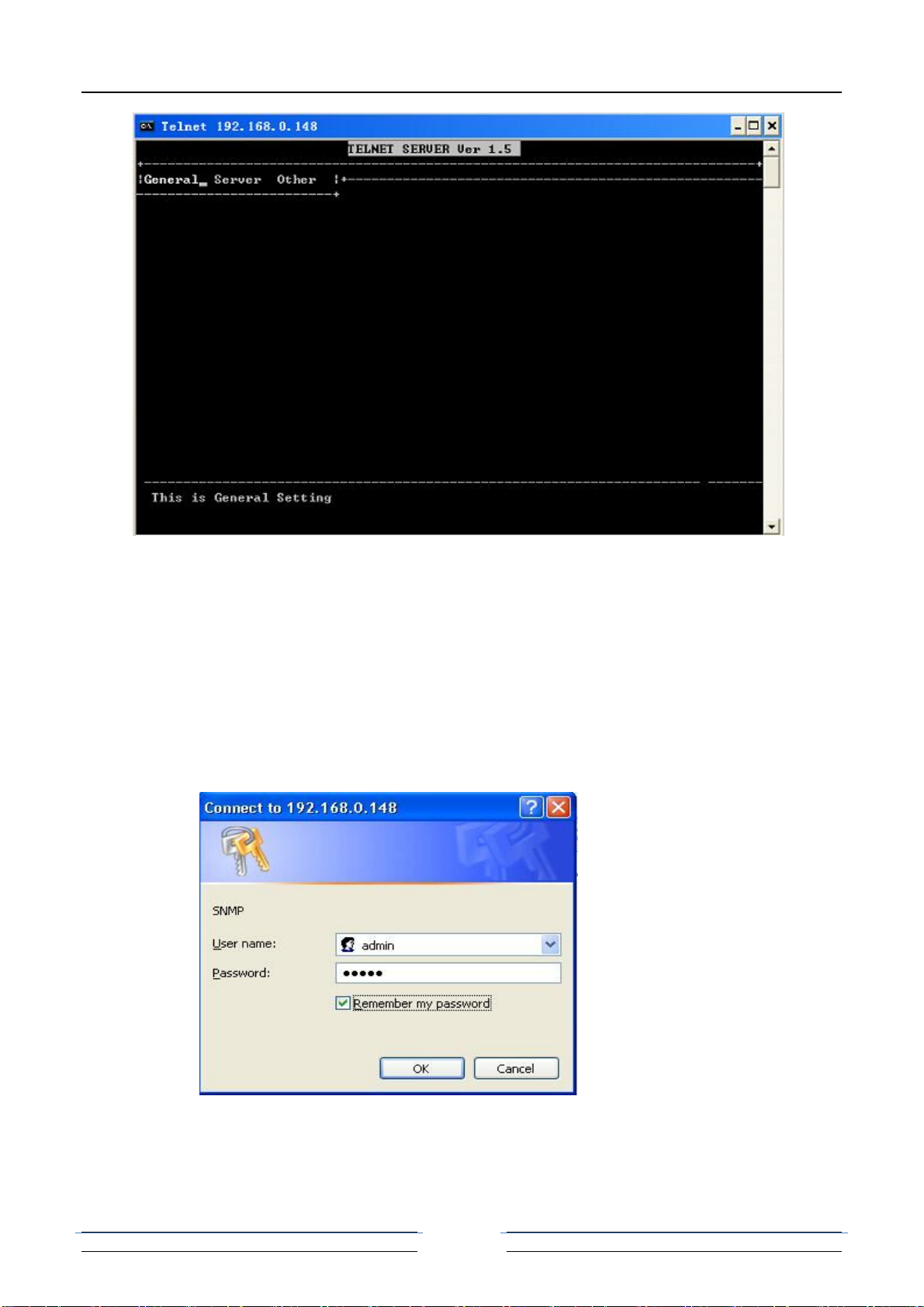
Telnet
Users can telnet from long-distance after collocating the IP address of the device.
Connect the PC to LAN, run the command “telnet A.B.C.D( default is 192.168.0.148,
input “c” or “e” when it come to the interface of Chinese/ English opt. input user
name and password to for the system to check( default is admin, admin). Then user
will enter into the main interface, showing as follows:
32PCM voice multiplexer user manual
13
Telnet provide graph interface mode( like the above one) and command line
mode( enter from the “command mode” in the “others” menu under the graph
interface mode.)
User can set the IP address and other parameters of the device under the graph
mode. And the command line mode is the same with the Console controlling mode.
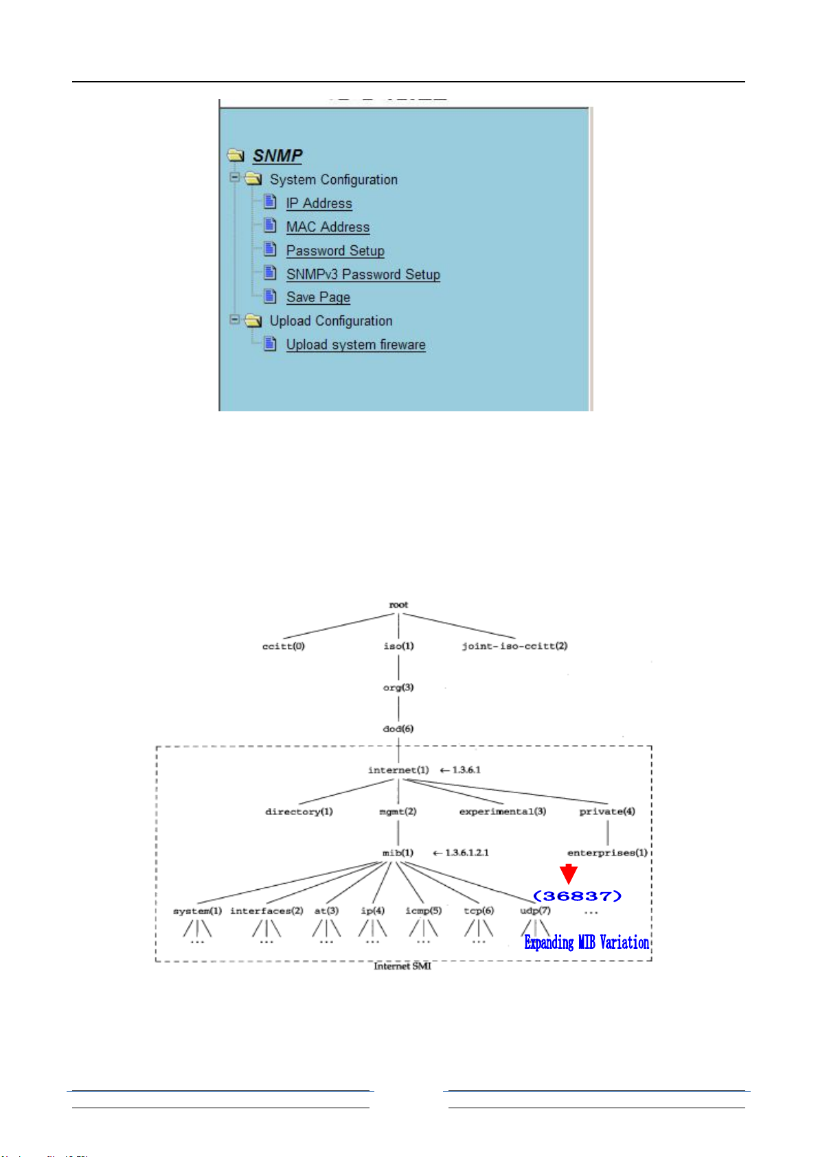
Http server
This system provides simple IE browse mode. Under this mode, user can realize
configuration or update operation.
Input the IP address of the SNMP card at the browser ( default is 192.168.0.148) to log on
the IE server.
The interface of Logging on is as follows:
Select Chinese/ English at the welcome interface after logging on( default user name is
admin, and password: admin). Then it entered into corresponding net page, showing as
follows:
32PCM voice multiplexer user manual
14
SNMP software
This system provides a set of SNMP Management Software Snmp Manage to operate
SNMP card and communication equipment. Please refer to the manual of SNMP software.
MIB Information
This system provides standard MIB variation.
MIB Tree Definition
In MIB tree, MIB variation behind 1.3.6.1.4.1.20353 is the one of communication equipment
which is corresponding to this system.
This system can be read by general SNMP network management software.
32PCM voice multiplexer user manual
15
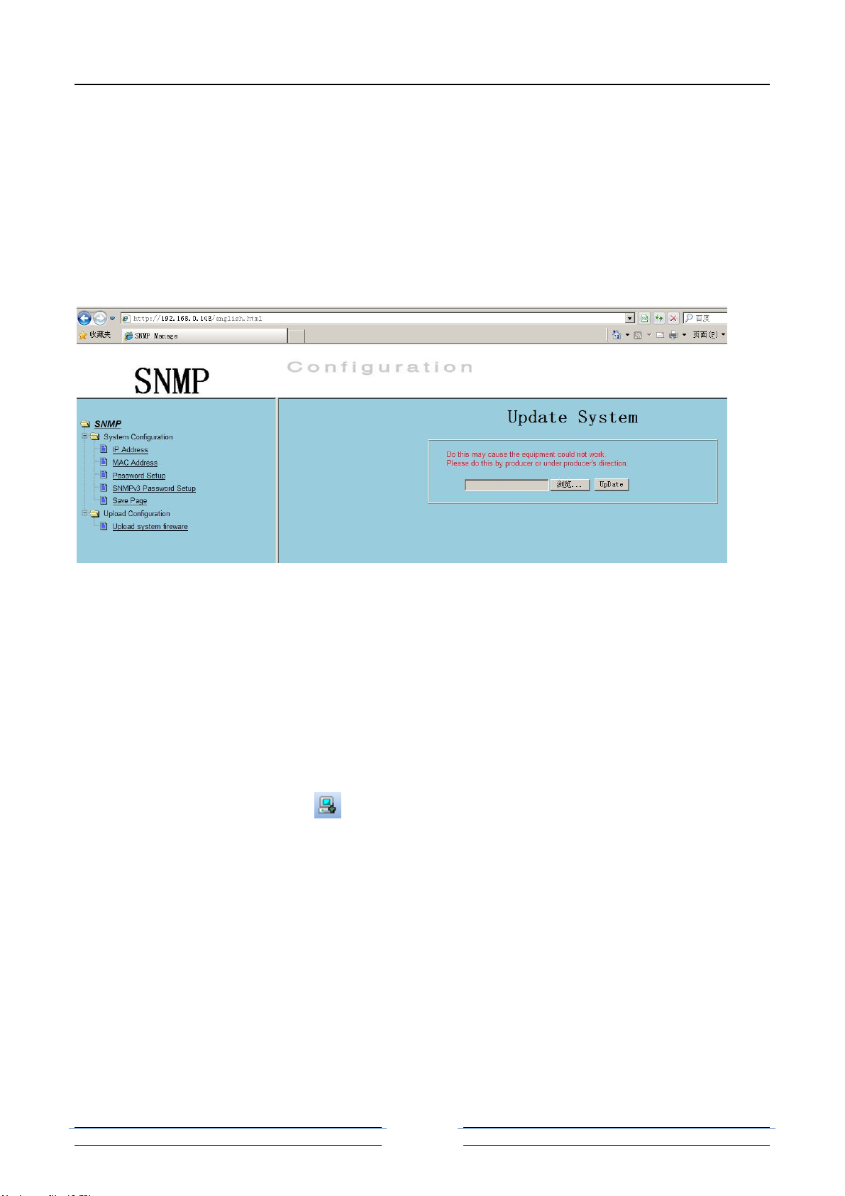
SNMP card software upgrade
The SNMP card software is stored in the FLASH. Software upgrade means FLASH
programming by SNMP card software upgrade function.
It needs software upgrade based on the 2 following situation. One is software upgraded,
which means replace the old software in terminal server by new; the other is when the
FLASH code destroyed, it could write new with the same version.
The update is realized by IE browser and the operation is easy.
Open “system firmware update” in the “system update” menu of the IE page, showing as
follows:
Click “browse”, select update document, then click “update”. Wait for some minute when
update( updating time is according to the size of the document). When presenting
“complete”, reboot the device to make it into effect.
Note: 1. If the update failed, the device will be destroyed abidingly. Please do it by the
factory or under the guidance of technician.
2. Do not browse through net page during updating. Furthermore, the system will not
work normally during update.
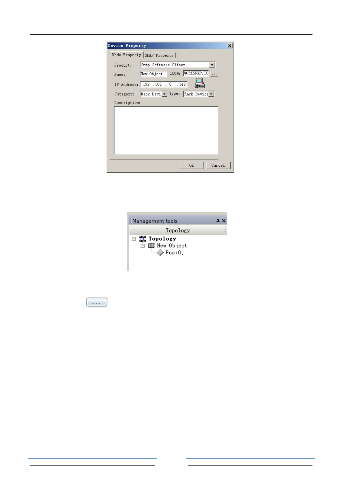
0214 30*Pots Fiber MUX SNMP Operate
Node
Select new node button in Topology View management Toolbar, to get following
dialog and enter the node information.
32PCM voice multiplexer user manual
16
Category: includes rack device (type: rack device) and others (type: SDH device, MSAP
device, TDMoIP device and PCM Fiber MUX.)
Since succeed to add rack, left Topology View management shows the homologous rack
information. And can display/shield the position and quantity of business card in current
running rack.
The following dialog in Topology View management shown if the device is online.
Click button to select device .INF file to open, and install the card devices
according to the clues. Otherwise, select the device management in Tool or the ico in
Toolbar 1 to add .INF file of card devices.
Note:
1. Please enter the device information in detail for better management.
2. The IP address is that of NM card.
3. Make sure that .INF file of specific device is added. If you have not got it,
please contact to device supplier.
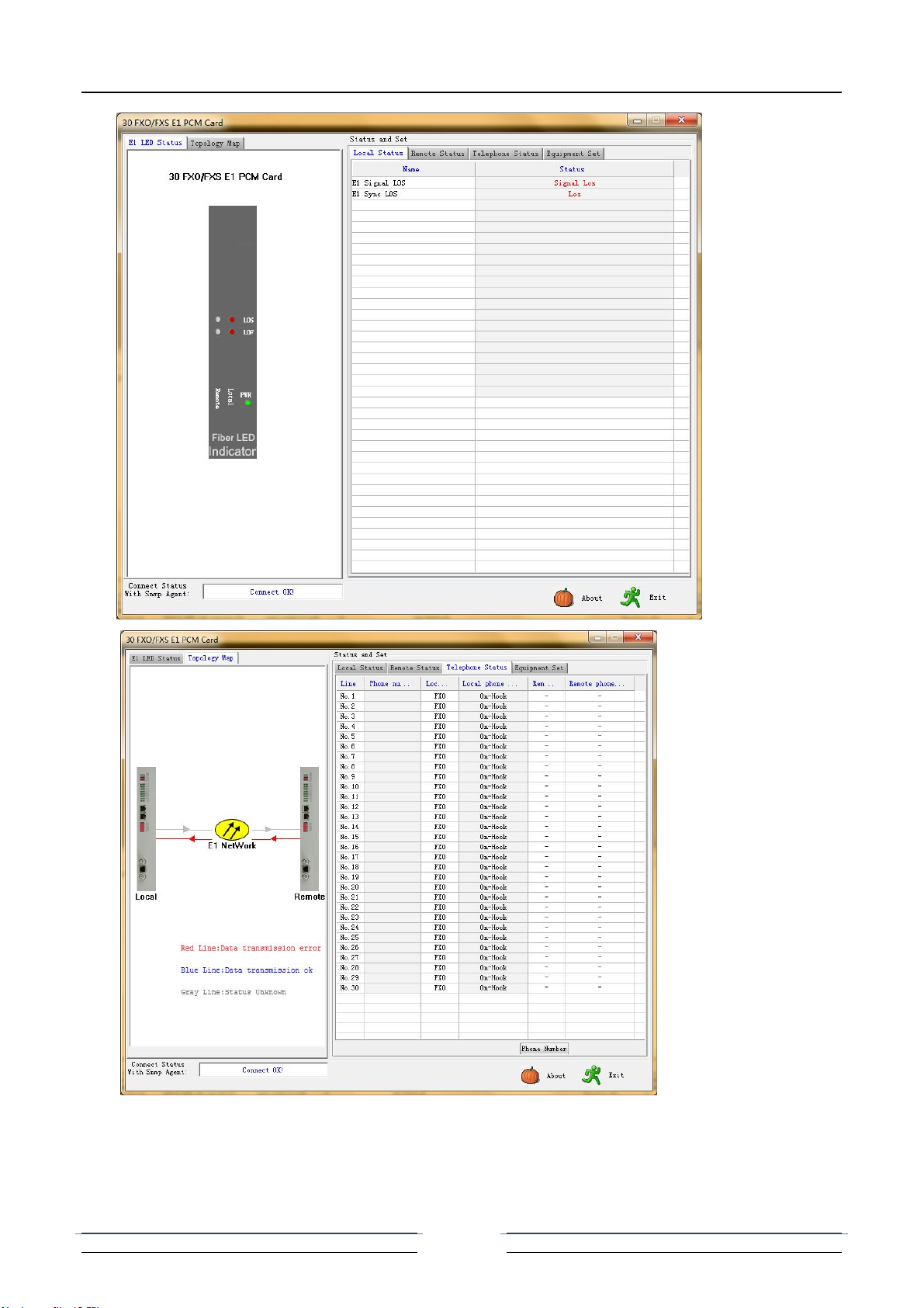
Device Current Running Info. Checking
Double click the running device or the business card in Topology to show rack info.. As
follows:

32PCM voice multiplexer user manual
17
Check rack info.: select NM card, select NM card info. in right-click menu, and get
following dialog.
Check business card info.: double click business card or select “State Set” in
right-click menu to enter the dialog. If the homologous .INF file is fixed, the state
dialog should show out. Following is one of 0202 30 Phone PCM MUX card:
32PCM voice multiplexer user manual
18

32PCM voice multiplexer user manual
19
Console Interface
Console sets interface. When matching 4 Ethernet interfaces, VLAN isolation mode
can be set by Hyper Terminal.
This is for PC hyper-terminal control.
Use DB9 cable to connect the PC's COM port with CONSOLE port;
Run the "hyper terminal" program under WINDOWS system, or run other third-party
serial port connection software, set the default parameters as following:
Baud rate: 9600;
Data byte: 8;
parity check: none;
Stop bit: 1;
Flow control: none;
Press "ENTER" continuously for several times, enter system's CLI interface and
begin management work.
========================== Main Menu ========================
== 1.current Ethernet information, Please input '1' ===
== 2.current PDH & E1 information, Please input '2' ===
== 3.current Phone & AUX Port information,Please input '3'===
== 4.Enter config menu, Please input '4' ===
== 5.Language Switch(Chinese or English)!Please input '5' ===
== 6.Factory Reset!Please input '6' ===
=============================================================
[PDH /]:
Submenu introduction
Table of contents


