Soundoff Signal ETSWDAS02 Installation instructions
ETSWDAS02 -
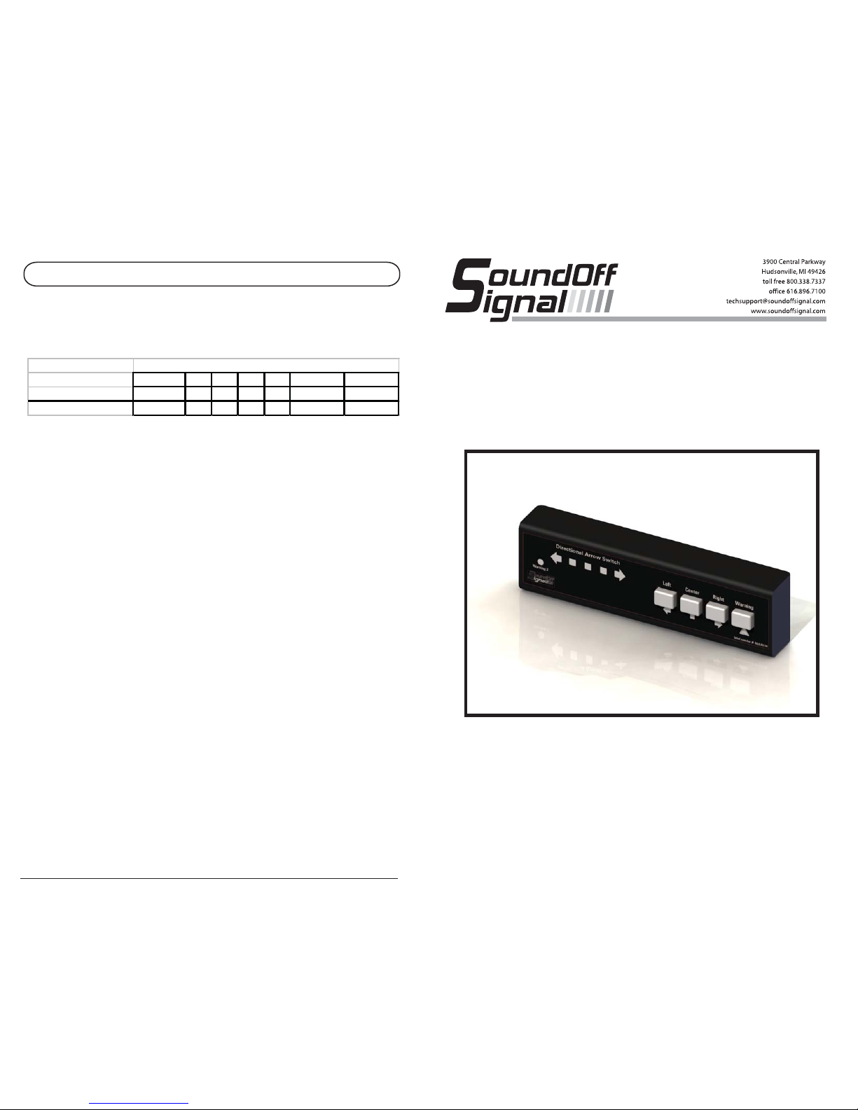
DIRECTIONAL ARROW SWITCH
INSTALLATION & OPERATION
INSTRUCTIONS
DIRECTIONAL ARROW SWITCH PAGE 6
123456
(Default)
7
Warning Mode One DW+EW DW EW DW EW DW EW
Warning Mode Two NA EW DW NA NA DW+EW DW+EW
Warning Mode Options
Changing between Warning output options:
Pressing the Warning button while in product configuration mode will change the outputs the warning
button controls. Below is a table of options
Directional Warning (DW) will apply voltage to the Yellow Wire (Warning One Output). End Warning
(EW) will apply voltage to the pink wire (Warning Two Output).
In modes 1,4, and 5 there is no warning mode two.
In modes 2,3,6, and 7 pressing the warning button once will activate warning mode one. Pressing the
warning button twice will activate warning mode two. To exit either warning mode, press the warning
button once.
The Current Warning Mode Option is designated by the yellow LEDs.
1. Warning Mode setting 1 is designated by yellow LED 1.
2. Warning Mode setting 2 is designated by yellow LED 2.
3. Warning Mode setting 3 is designated by yellow LED 3.
4. Warning Mode setting 4 is designated by yellow LED 4.
5. Warning Mode setting 5 is designated by yellow LED 5.
6. Warning Mode setting 6 is designated by yellow LED 1 and 5.
7. Warning Mode setting 7 is designated by yellow LED 1, 2, and 5.
Note: If the warning 2 RED LED is illuminated and an arrow button is pressed, they will both be on at
the same time. Pressing the Warning button will turn of the Warning 2 output. Pressing the arrow
button that is green will turnoff the Arrow Function.
To exit product conguration mode:
By holding down the Left and Warning Buttons together for 2 seconds, product configuration mode
can be exited. The unit will emit two short beeps. At this time release the buttons.
ETSWDAS02 10.12

DIRECTIONAL ARROW SWITCH PAGE 1
PRODUCT SPECIFICATIONS
Pin # Wire Color Function
1 Red +10-30 Vdc Power Input
2 White / Red Master / Ignition switch (0u = Stand by)
3 Black (-) Ground
4 NA Not populated
Pin # Wire Color Function (All Outputs +Vdc Active High)
1 Blue LEFT Arrow Indicator Output Control
2 Brown CENTER Arrow indicator Output Control
3 Green RIGHT Arrow Indicator Output Control
4 Yellow WARNING 1 Output Control
5 Pink WARNING 2 Output Control
6 Red/Black N/A
CN1 (2x2, Power Input Connector)
CN2 (2x3, Control Output Connector, Low Current: 0.25A Max)*
Input Voltage: +10-30 Vdc
Polarity: Negative Ground
Reverse Polarity Protection: Yes
Transient Protection: Yes
Operating Temperature: -40C to +85C
Current Draw: 0.8 Amps
Standby Current: Zero Amps
+Vin Fuse: 5 Amps ATO
Dimensions 166mm x 22mm x 45mm (6.55" x 0.88" x 1.76")
170 mm (6.7") w/ Mounting Bracket
Shipping Weight .65 lbs
Electrical
Mechanical
WIRE COLORS/USES
DIRECTIONAL ARROW SWITCH PAGE 5
Product Conguration Mode:
By holding down the Left and Warning Buttons together for 2 seconds, product configuration mode can
be entered. The unit will make a long“beep”, and all of the buttons will turn green when product
configuration mode has been entered.
Changing the level of brightness on the red LEDs:
The level of brightness can be changed (high, low, and off) by pressing the Left button in product
configuration mode.
Changing level of sound:
The volume of the speaker can be changed (high, low, and off ) by pressing the Right button in product
configuration mode.
Changing between Center output options:
Which wires the Center button applies power to can be changed in the product configuration mode by
pressing the Center Button.
When the Yellow LED in the middle is lit, the unit will apply power to the Brown Wire
When the second and fourth LED’s are lit, the unit will apply power to the Blue and Green wires.
* Must NOT exceed a total of 0.25 Amp for any combination of active outputs.

DIRECTIONAL ARROW SWITCH PAGE 2
CONNECTING THE WIRES:
Black Wire (Ground)
Connect to Reliable Ground
To minimize field service issues, it is recommended that the ground wires be
connected directly to the ground terminal of the battery.
Red Wire (Power Input)
Connect to a reliable +12v or +24v power source
White / Red Wire (Master / Ignition switch)
Connect to a reliable +12v or +24v power source
BLACK
+12Vdc RED
+12Vdc
WHITE/RED
Wire Color Function Connection
Black Ground Reliable Ground
Red Constant power +12v or +24v
White w/ Red Switch Master/Ignition switch
Pressing the“Left” Button will apply power to the Blue wire (Left Arrow Direction), and display the
left arrow pattern on the yellow LED’s.
Pressing the“Center” button will apply power to the Brown Wire (Center Arrow Direction), and
display the center out pattern on the yellow LED’s.
Pressing the“Right” button will apply power to the Green wire (Right Arrow Direction), and display
the right arrow pattern on the yellow LED’s.
Pressing the“Warning button will apply power to the Pink or Yellow Wire,and display an alternating
pattern on the yellow LED’s.
DIRECTIONAL ARROW SWITCH PAGE 4

DIRECTIONAL ARROW SWITCH PAGE 3
INSTRUCTIONS FOR LED TRAFFIC MASTER:
ETTMLEDW3 and ETTMLEDDRA
(STANDARD WIRING SETUP: LOOKING AT BAR, CABLE EXITS ON THE LEFT REAR)
Pink Wire (Warning Two)
Connect to Pink Wire of the Traffic Master
Yellow Wire (Warning One)
Connect to either the Green or Purple wire of the traffic master (depending on the desired
flash pattern)
Blue Wire (Left Arrow Direction)
Connect to Dark Green wire of the Traffic Master.
Brown Wire (Center Arrow Direction)
Connect to Yellow wire of the Traffic Master.
Green Wire (Right Arrow Direction)
Connect to Blue wire of the Traffic Master.
Please see page 10 for instructions on how to change between center output options.
Configure to apply power to the brown wire (Center Option 1)
Note: If you are using optional wiring, then the Dark Green and Blue wires must swap.
Blue Wire (Left Arrow Direction)
Connect to the Blue wire of the Traffic Master
Green Wire (Right Arrow Direction)
Connect to the Dark Green wire of the Traffic Master.
To turn off the end warning, press the warning button. To turn off the arrow functions press the
arrow button.
BLACK
GROUND
+10-30Vdc
RED
YELLOW
PINK
GREEN
BLUE
YELLOW
PINK
GREEN
PURPLE
BLUE
Either-or
NOT BOTH
+10-30Vdc
+10-30Vdc
RED
WHITE/RED
BLACK
PURPLE
Table of contents
Popular Switch manuals by other brands

Cisco
Cisco CBS Series Get to know

3Com
3Com 4007 Getting started guide

Dell
Dell PowerConnect 2124 System information guide

Dell
Dell Powerconnect W-ClearPass Hardware Appliances Hardware installation guide

VigilLink
VigilLink VLKV-HD21 user manual

LevelOne
LevelOne IGP-0871 Quick Installation and Initial Configuration


