SoundTracs SOLO Logic User manual

•
I
I
LOGIC
Console
utomation
System
Operating Manual • Issue A

Chapter 1 Introduction
Chapter 2 - Tutorial
Chapter 3 Hook ups
Chapter 4 Reference section
Operating controls
Mix modes
Lontents
What is automation
Examples of automated mixes
The control panel
The fader controls
The ON/OFF buttons
MlDI ports
Hook up
Turning the automation on
Synchronisation
The first recording
Replaying the mix
Updating the mix
Re-recording
Isolate mode
Glohal fader modes
Recording ON/OFF buttons
Saving the mix
Grouping
Screen display
Slave mode
Tapclcss studios
Conventional studios
Control panel
Fader controls
Tape machine controls
Switching on the automation
Recording the mix
Replaying the mix
Fader trim mode
ON bulton update mode
Rc-rccording faders
Fader nulling
Fader isolate mode
Global fader modes
Global ON button modes
1
3
3
4
5
6
6
7
9
10
10
10
II
12
12
13
13
14
15
16
17
18
19
21
22
23
25
25
25
26
26
26
27
27
28
28
29
29
29
S..vitching the automation off
30
Memory
30
Accessing the menu
31
Null
"
,-
Null mode
32
Auto null time
32
Match 32
View
32
Clear
33
File
33
Load
33
S'\ e 34
Name
34
Setup
35
~[ channel
35
Slave
35
Send 35
Note on transmit
36
Timecode source
36
MTC to MIDI I 37
MTC to MIDI 2 37
Timecode standard
38
Safe 38
Grouping
39
-
"
I
II
I
I
I
•
I
r
,
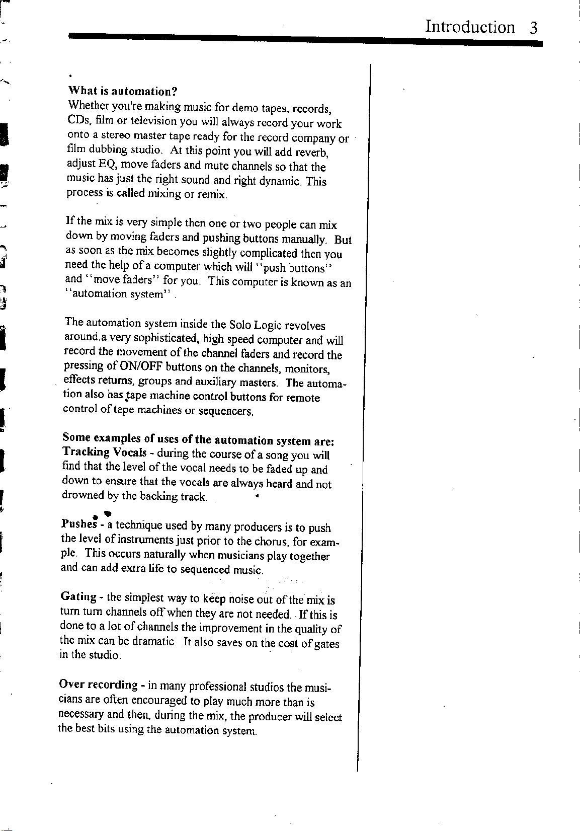
What is automation?
Whether you're making music for demo tapes, records,
CDs, film or television you will always record YOUf work
onto a stereo master tape ready for the record company or
film dubbing studio. At this point you will add reverb,
adjust EQ, move faders and mute channels so that the
music has just the right sound and right dynamic. This
process is called mixing or remix.
If the mix is very simple then one or two people can mix
down
by
moving faders and pushing buttons manually. But
as soon as the mix becomes slightly complicated then you
need the help of a computer which will "push buttons"
and "move faders" for you. This computer is known as an
"automation system" .
The automation system inside the Solo Logic revolves
around. a very sophisticated, high speed computer and will
record the movement of the channel faders and record the
pressing of ON/OFF buttons on the channels, monitors,
effects returns, groups and auxiliary masters. The automa-
tion also has Jape machine control buttons for remote
control of tape machines or sequencers.
Some examples of uses of the automation system are:
Tracking Vocals - during the course of a song you will
find that the level of the vocal needs to be faded up and
down to ensure that the vocals are always heard and not
drowned by the backing track. •
•
Pushe: - a technique used by many producers is to push
the level ofinstruments just prior to the chorus, for exam-
ple. This occurs naturally when musicians play together
and can add extra life to sequenced music.
Gating - the simplest way to keep noise out of the mix is
tum tum channels off when they are not needed. If this is
done to a lot of channels the improvement in the quality of
the mix can be dramatic. It also saves on the cost of gates
in the studio. .
Over recording - in many professional studios the musi-
cians are often encouraged to play much more than is
necessary and then, during the mix, the producer will select
the best bits using the automation system.
Introduction 3
4 Introduction
Vocal pre-mixes - as with musicians, the vocalist is also
encouraged to sing more than is necessary, often recording
10 or 15 tracks of the same lead vocal. The producer then
uses the automation system to piece together the best bits
into one vocal take.
Special effects - with an automation system you can do
much more than just record fades. It is simple to create
modulation and tremolo effects and,
by
using 2 channels,
you can create your own auto panning effects.
Seamless compression - many professionals do not use
compressors when they have an automation system. In-
stead they. use the faders to drop levels when signals get
too hot. When the automation is played back you have
programmable compression without the "squashing" of
conventional compressors.
This gives you some idea some what the Logic automation
can be used for .... once you've learnt how to use it.
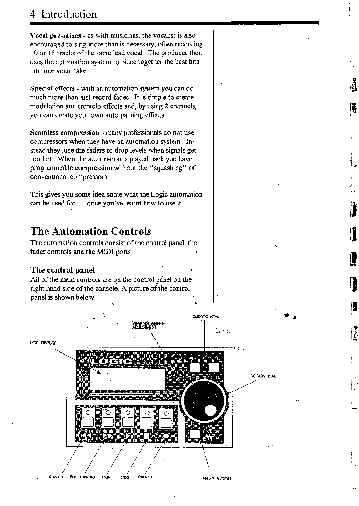
The Automation Controls
The automation controls consist of the control panel, the
fader controls and the MIDI ports.
The control panel
All of the main controls are on the control panel on the
right hand side of the console. ,A picture of the control
panel is shown below:
•
LCD DISPlAY
/
Rewind FO:;Iforward Ploy Stop
•. 1:; .~.
ENTER BUTTON
r,
;.1
II
\1
I
L
\1
l"~
.~
Ii
I
,~

r
r
'I
U
a
I
I
I
I
(
~
I
t
,
l
The controls are:
1. LCD display
2. Left and right keys - the left and right keys move the
LCD cursor to the left or to the right. The left button is
also an EXIT button for exiting menus.
3. Rotary dial - the rotary dial selects options from the
menus and is used to enter
text
4. ENTER button - the ENTER button is used to enter
menus and to "say yes". In other words
it
is used to
confirm something.
5. Rewind - used to rewind the automation and tape
machine/sequencer.
6. Fast forward - used to fast forward the automation and
tape machine/sequencer.
7. Play - used to play the automation and tape machine
sequencer.
8. Stop - used to stop the automation and tape machine
sequencer. Pressing stop twice resets the automation and
tape machine to zero .
.
9. Record - used to drop the tape machine into record.
10. Viewing angle - used to alter viewing angle of the
LCD display. Adjustment is via a small flat head screw-
driver.'j L.'.'
•
Fader Controls .
"
.
Alongsfdeeach channel fader are two switches and two
LEDs as shown opposite. The fader controls are:
2. Fader RECORD
These buttons and LEDs also provide a,'number of Qth,~r.
. ' .'- .~,.> "'"
functions as explained in the tutorial.
Introduction 5
PlAY BUTTON
PlAY LED

6 Introduction
On/Off buttons
Most of the ON/OFF buttons on the console are controlled
by
the logic automation and can be recorded
by
the com-
puter. The buttons which are under automatic control are
the channel ON buttons, the monitor ON buttons, the
effects return
ON
buttons, the group ON buttons and the
auxiliary master ON buttons.
MIDI PORTS
On the rear of the console are
two:rvn:nr
ports:.MIDI 1
and MIDI 2 as shown below:
II
Also on the rear panel is a 9 pin D type connector. This is
a serial port from the internal computer and is provided for
future expansion to the Logic automation system.
Normally MIDI 1 is connected to the sequencer and :MIDI
2is connected to a tape machine, but you can use them in
any way you choose. The logic automation lets you
configure them in software as you will see later.
--MIDI :--
IN lHRU OIJT
•••
--MIDI2--
IN THRU
out
•••
f_
L
~
~
fI
•••
I)
\l
•
r
d;
I.
•
,
I
t
,
I
l
I
I
Chapter
2Tutorial
Hook up
Turning the automation on
Synchronisation
The first recording
Replaying the mix
Updating the faders
Re-recording
Isolate mode
Global fader modes
Recording on off buttons
Saving a mix
Grouping
Screen display
Slave mode
7
9
10
10
10
11
12
12
13
13
14
15
16
17
17

,
.
~
I
I
I
I
I
i
I
,
,
Tutorial 9
The simplest way to learn the automation system is to do a
mix. The following pages will run you through a simple
mix and the basic functions of the automation system.
Once you are familiar with the automation you will be able
to read the reference section for a complete description.
For this tutorial you will need a MIDI sequencer which
reads MTC and some MIDI instruments such as keyboards
and
drum
machines. You should record a simple song into
the sequencer using a keyboard and drum machine which
we can then mix down during this
tutorial.
The diagram
below shows how your console should be connected. (For
more sophisticated studio connections see 'Hook ups'.) If
you are unsure how to connect the audio signals then read
the console operating manual.
SLAVE
MIDI SEQUENCER
O~
1111111111.1111111111 II
MASTER
SOLO LOGIC CONSOLE
10 Tutorial
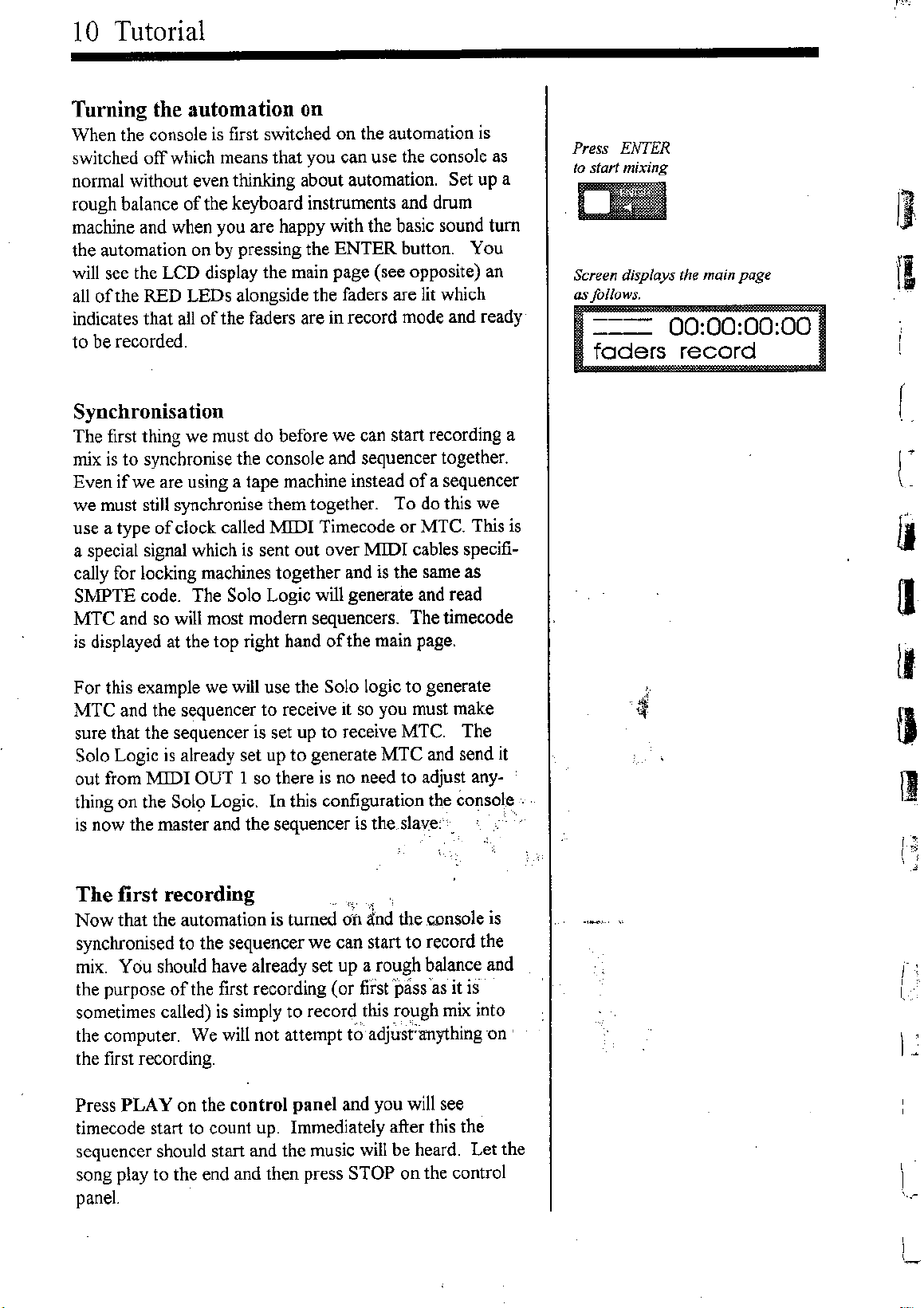
Turning the automation on
When the console is first switched on the automation is
switched off which means that you can use the console as
normal without even thinking about automation. Set up a
rough balance of the keyboard instruments and drum
machine and when you are happy with the basic sound tum
the automation on by pressing the ENTER button. You
will see the LCD display the main page (see opposite) an
all of the RED LEDs alongside the faders are lit which
indicates that all of the faders are in record mode and ready
to be recorded.
Press ENTER
to start mixing
011
Screen displays the main page
as/allows.
===
00:00:00:00
faders record
II
II
Synchronisation
The first thing we must do before we can start recording a
mix is to synchronise the console and sequencer together.
Even
if
we are using a tape machine instead ofa sequencer
we must still synchronise them together. To do this we
use a type of clock called 11IDI Timecode or MTC. This is
a special signal which is sent out over MIDI cables specifi-
cally for locking machines together and is the same as
S:MPTE
code. The Solo Logic will generate and read
MTC and so will most modem sequencers. The timecode
is displayed at the top right hand of the main page.
For this example we will use the Solo logic to generate
MTC and the sequencer to receive it so you must make
sure that the sequencer is set up to receive MTC. The
Solo Logic is already set up to generate MTC and send it
out from "MIDIOUT 1 so there is no need to adjust any-
thing on the Sol9 Logic. In this configuration the console .
is now the master and the sequencer is the slave:'.
The first recording
« ,
Now that the automation is turned
on
ind the console is
synchronised to the sequencer we can start to record the
mix. You should have already set up a rough balance and
the purpose of the first recording (or first pass 'as it is
sometimes called) is simply to record this rough mix into
the computer. We will not attempt to'adju'st<anything -on
the first recording.
Press PLAY on the control panel and you will see
timecode start to count up. Immediately after this the
sequencer should start and the music will be heard. Let the
song play to the end and then press STOP on the control
panel.
r
(-
II
a
I.
,
4'
fJ
lJ
• ''lc
I,.,
i
I
,
,
I~
l
,
,
,
I
I
I
I
I
I
I
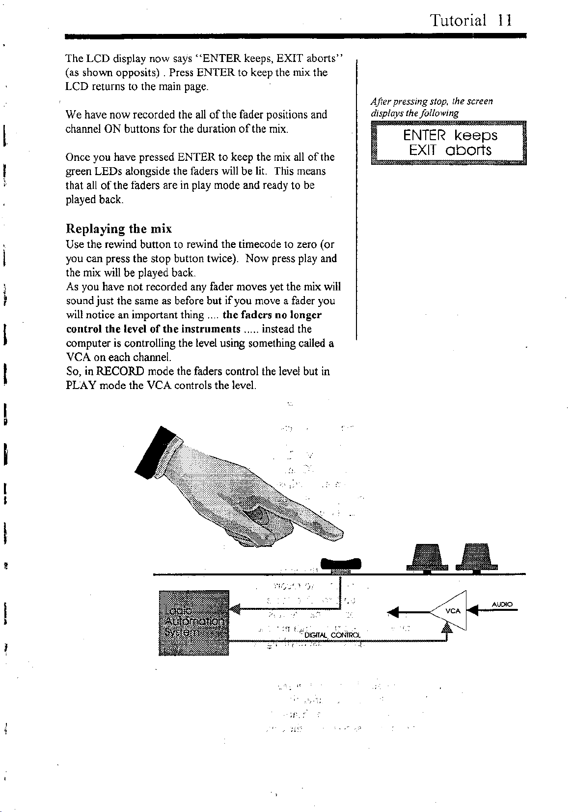
The LCD display now says "ENTER keeps, EXIT aborts"
(as shown opposits) . Press ENTER to keep the mix:the
LCD returns to the main page.
We have now recorded the all of the fader positions and
channel ON buttons for the duration of the mix.
Once you have pressed ENTER to keep the mix all of the
green LEDs alongside the faders will be lit. This means
that all of the faders are in play mode and ready to be
played back.
Replaying the mix
Use the rewind button to rewind the timecode to zero (or
you can press the stop button twice). Now press play and
the mix will be played back.
As you have not recorded any fader moves yet the mix will
sound just the same as before but
if
you move a fader you
will notice an important thing .... the faders no longer
control the level of the instruments ..... instead the
computer is controlling the level using something called a
VCA on each channel.
So, in RECORD mode the faders control the level but in
PLAY mode the
VeA
controls the level.
'-j
Tutorial II
After pressing stop, the screen
displays the following
ENTER keeps
EXIT aborts
&&
I
.:~1
",.,
- DIGITAL CONTROL
:,
_
..
;'-.;
AUDIO
VCA
.-
.',
j ; •
•1"
12 Tutorial
Updating the faders
o,bviously the first pass was not very interesting and the
whole point of having automation is to add life and dynam-
ics to the mix. What we want is to play the mix back and
record new fader moves on top, just like overdubbing on a
sequencer. In automation jargon overdubbing is called
TRIM mode.
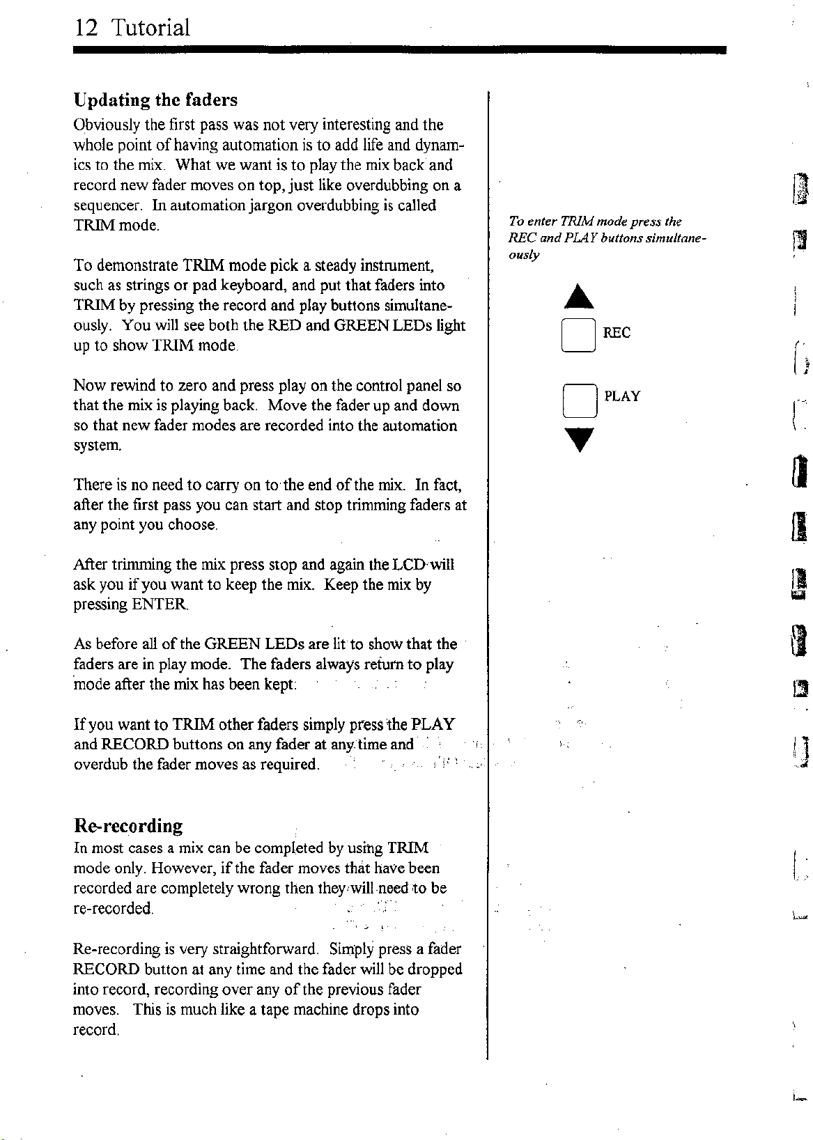
To demonstrate TRIM mode pick a steady instrument,
such as strings or pad keyboard, and put that faders into
TRIM by
pressing the record and
play buttons simultane-
ously. You will see both the RED and GREEN LEDs light
up to show TRIM mode.
Now rewind to zero and press play on the control panel so
that the mix is playing back. Move the fader up and down
so that new fader modes are recorded into the automation
system.
There is no need to carry on to,the end of the mix. In fact,
after the first pass you can start and stop trimming faders at
any point you choose.
After trimming the mix press stop and again the LCnwill
ask you if you want to keep the mix. Keep the mix by
pressing ENTER
As before all of the GREEN LEDs are lit to show that the
faders are in play mode. The faders always return to play
'mode after the mix has been kept:
If you want to TRIM other faders simply press the PLAY
and RECORD buttons on any fader at anytime and
overdub the fader moves as required.
Re-recording
In most cases a mix can be completed by using TRIM
mode only. However, if the fader moves that have been
recorded are completely wrong then theY
1
will-needto be
re-recorded.
'j •
Re-recording is very straightforward. Simply press a fader
RECORD button at any time and the fader will be dropped
into record, recording over any of the previous fader
moves. This is much like a tape machine drops into
record.
To enter TRIM mode press the
REC and PIAY buttons simultane-
ously
•••
DREC
DPLAY
1.1
13
I

I
J
However, you must beware:
if
the level of the
VeA
is not
the same as the level of the fader
it
is possible to hear a
jump in level when the fader is dropped into record .. If
you want to be sure that the fader level matches up to the
VeA
level then you must use the nulling indicators.
To explain the nulling indicators choose a fader whose
level in the mix is static. Now move the fader to near the
bottom. Press play on the control panel and then press
record on the fader. You will see that the RED LED
flashes, indicating that the
fader
needs to be moved up-
wards. Move the fader slowly upwards and at the point
where the fader level and the
VeA
level match, the fader
will drop into record. If the fader needed to move down-
wards the green LED would have flashed.
The nulling indicators also operate when a channel is
dropped back into play.
If you prefer you can switch the nulling off. This is ex-
plained in the reference section.
If you make a mistake during re-recording don't worry,
you can abort the mix and return to thlf previous pass.
Isolate mode
If things get a little confusing you can go back to manual
operation on any fader by switching the LEDs, off;- Now,' ':
the fader controls the audio signal and the automation will
have no effect on that fader.
(If you want to revert back to manual operation for the
entire console then select AUTO en the LCD using the'
dial, press the right cursor key, select OFF using the dial
and then press ENTER.)
Global fader modes
It is possible to put any number of faders into any-mode
you like, there is no limit but if you want to switch aU:of.
the faders into record, play, trim or isolate simul1aneously ,
you can do this by selecting FADERS on the LCD, press
the right cursor, select the mode you want and press EN-
TER You will see all of the LEOs onthefade~s Change
accordingly_ ."',,
Tutorial 13
When RED LED fashes move the fader
up. When GREEN LED flashes move
fader down.
.•• RED
o
o
.••• GREEN

014 Tutorial
Updating ON/OFF buttons
So far we have only updated fader moves but this is only
part of the mix process, If you want the mix to be dynamic
and free from noise you will have to update the ON/OFF
buttons too. The channels, monitors, groups, master
effects sends and effects returns all have ON/OFF buttons
that can be automated.
Recording these ON/OFF buttons is extremely simple.
They are always in "update mode" in other words they are
in play mode but with record ready so if you press an ON
button during a mix
it
will be recorded. That's all there is
to
it.
To stop recording press the stop button.
As with the faders there are global modes for all of the ON
buttons. This allows you to drop all ON buttons into
record simultaneously_ (see reference section).
Because the effects sends are automated we can use the
automation system to add effects to the mix automatically.
To do this connect an effects device such as a reverb unit
to the console as shown below.
EFFECl'S lNT
[0
-+ •••
:1
r
I
\
..
A••"
~
I11IIIII111111111111 . II
r ].tt t t t t t t t t t t t t t t t t t rtt
SOLO LOGIC CONSOLE
L
Now turn on aux output 1 and send some signal from one
of the channels to the reverb unit. Press play on the
control panel and turn the reverb send on and offby
pressing the ON/OFF button on aux output number one.
At the end of the mix press stop and keep the mix. Now
if
you replay the mix the reverb will be added automatically.
As with the faders the mutes can be recorded at any time,
it is not necessary to start at the beginning of the mix or
run to the end of the mix.
Saving a mix
Your mix will always be kept in memory even
if
the con-
sole is switched off but
if
you want to start a new mix you
may want to save the mix more permanently. You can do
this
by
sending the mix data to a sequencer or a:MIDI data
recorder as a SYS EX file (If you are unsure about SYS
EX files consult your sequencer manual).
To save the mix to a sequencer select menu using the
rotary dial and press ENTER. Using the dial select FILE
and press ENTER.
Tutorial 15
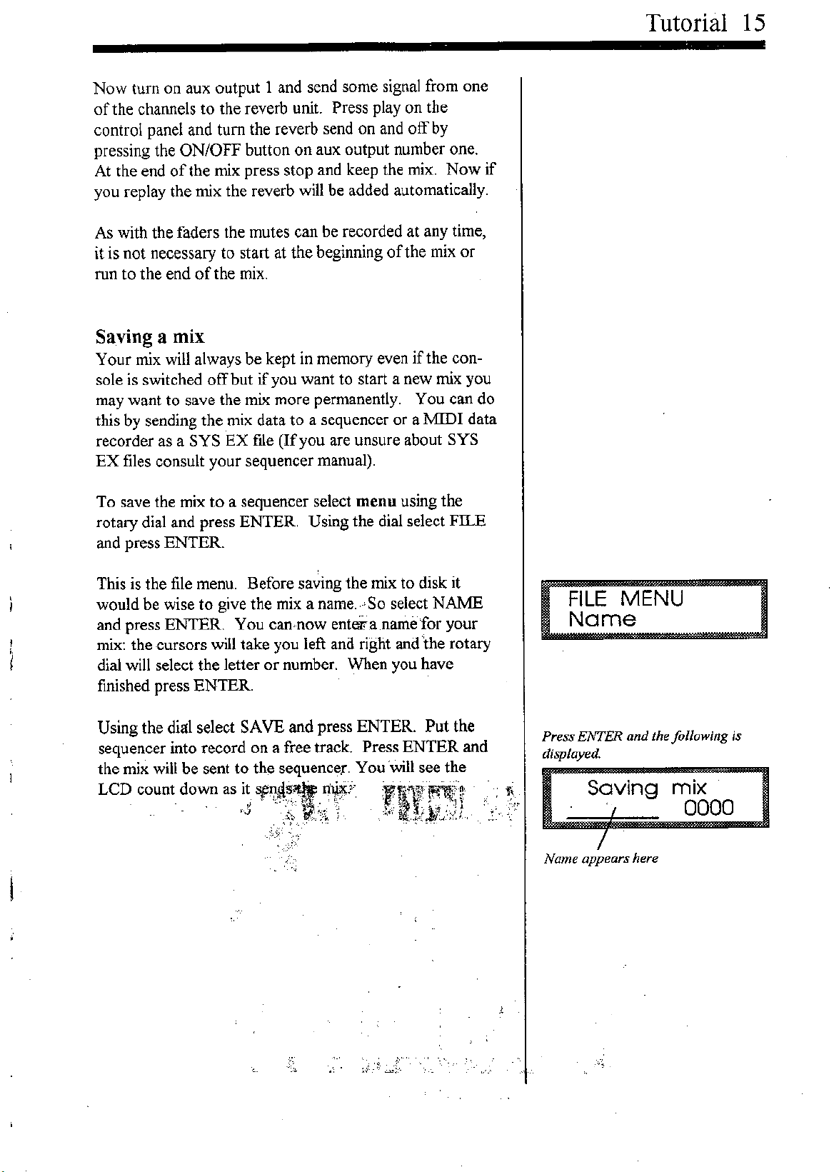
This is the file menu. Before saving the mix to disk it
would be wise to give the mix a name. ,-'So select NAME
and press ENTER. You can,now enterra ,namefor your
mix: the -cursors will take you left and right and 'the rotary
dial will select the letter or number. When you have
finished press ENTER.
:::::1
Press ENTER and the following is
displayed.
Using the dial select SAVB and press ENTER. Put the
sequencer into record on a free track. Press ENTER and
the mix will be sent to the sequencer. You will see the
LCD count ~o~n as ,ij
~~~t~~J'
:Fllr~u,
-."
Saving
,
/
Name appears here
mix
0000
16 Tutorial
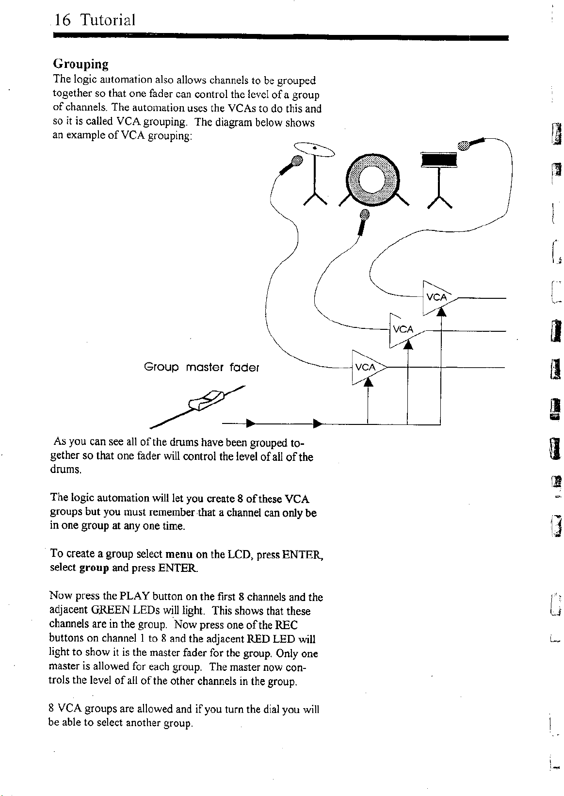
Grouping
The logic automation also allows channels to be grouped
together so that one fader can control the level of a group
of channels. The automation uses the
yeAs
to do this and
so
it
is called
VeA
grouping. The diagram below shows
an example of
VeA
grouping:
VCA
Group master fader
As you can see all of the drums have been grouped to-
gether so that one fader will control the level of all of the
drums.
The logic automation will let you create 8 of these
yeA
groups but you must remember that a channel can only be
in one group at anyone time.
To create a group select menu on the LCD, press ENTER.,
select group and press ENTER
Now press the PLAY button on the first 8 channels and the
adjacent GREEN LEDs will light This shows that these
channels are in the group. Now press one of the REC
buttons on channell to 8 and the adjacent RED LED will
light to show it is the master fader for the group. Only one
master is allowed for each group. The master now con-
trols the level of all of the other channels in the group.
8
VeA
groups are allowed and if you turn the dial you will
be able to select another group.
VCA
VCA
I)
Iii
II
II
i
,'--

Screen display
Because of the complexity of automation
it
is ideal
if
there
is a screen to display the fader levels. The logic automa-
tion sends out continuous controllers for each of the faders
and on buttons on the console. This means a conventional
sequencer which has some form of graphical :MIDI mixer
will be able to display the fader levels and mutes.
Slave mode
Although the automation is on board it is possible to
switch the Logic console to slave mode so
it
can be con-
trolled from a sequencer. You can turn slave mode on and
off under the :MIDI page (see reference section). When
slave mode is on, the faders on the console do not control
the level but instead the level is controlled
by
the
sequencer. As with the screen display above continuous
controllers are used to adjust the level of the faders. How-
ever, due to the lower resolution of :MIDI the smoothness
of the level control is reduced.
.
Tutorial 17

Chapter
3
Hook ups
Tapeless studios
Conventional studios
19
2l
22

20 Hook
uP.s _
The way in which the MIDI cables are connected will depend on whether you use just a sequencer
or a tape machine and sequencer. The following drawings show how your MIDI equipment is
normally connected in each case.
Tapeless studios
At the heart of the tapeless studio is the sequencer so normally the sequencer should be the mas-
ter which generates MTC. In this case the console should be connected as shown below. You
can see that the sequencer is the master and the hard disk recorders, samplers and console are all
slaves. (If your sequencer can only read MTC or you want to control the sequencer from the
console then the console should be the master, see the hook up in the tutorial section.) The
console timecode source should be set to MIDI 1 and MTC should be sent to MIDI port 2
if
you
have a hard disk system which requires MTC.
r:
I
I
'.
I:::
[
MASTER
MlDI SEQUENCER
N
OUT
•
•
•
SYN1'l1 OIl
DRUM MODLlE
[0 ••••••
+ •••
:I~.•~" _
]
SLAVE
HARD [)jSl< RECORDER
0'
me
reading ""mole,
• 1~':2ifttJI
000000
•
MOl PORT 2 MOl PORT 1
I
IN
our
N OUT
1111111.1111111111111 II
"
1
L
I•
I~
SLAVE
SOLO LOGIC CONSOLE
I.
------ --r- --
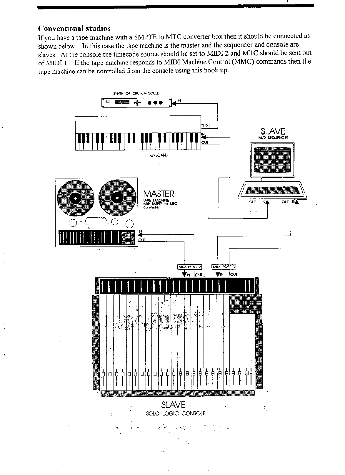
Conventional studios
If you have a tape machine with a Sl\1PTE to MTC converter box then it should be connected as
shown below, .In this case the tape machine is the master and the sequencer and console are
slaves. At the console the timecode source should be set to rvtIDI 2 and MTC should be sent out
ofMlDI
1.
If the tape machine responds to MIDI Machine Control (MJvIC) commands then the
tape machine can be controlled from the console using this hook up.
S'r'NI"H OIl DRUM MOCULE
SLAVE
MIDI SEQUENCER
om ,
om "
MASTER
TAPEMACH~E
with SMPTE 10 MTC
ccrwe<ler
co.......
+ •••
:1.••-"--
]
111111111111111111II
I1II11I1111111111111 II
"'
"\
.,
I;;:,; / \
J'
MIDI PORT 2
'N
.,
,'"
MIDI PORT \
N ""'
SLAVE
SOLO LOGIC CONSOLE
"",
Table of contents
Popular Dj Equipment manuals by other brands

Chauvet Professional
Chauvet Professional ROGUE R3X WASH user manual
Techni-Lux
Techni-Lux Pro Series Tracker SPOT250 manual

Technical Pro
Technical Pro LGMEGAx user manual

Chauvet DJ
Chauvet DJ COLORband T3 BT user manual

Showlite
Showlite SPS-121 instruction manual

Ignition
Ignition LED Blinder 4 user manual


