Sourcetronic ST600 Series User manual
SOURCETRONIC –Quality electronics for service, lab and production
ST600 Series Frequency Inverter
User Manual

Frequency Inverter ST600 Series High-Performance Multifunction VFD Preface
-i-
Preface
Thank you for choosing the ST600 series high-performance multifunction VFD.
The frequency inverter ST600 series VFD is a high-performance and multipurpose VFD aiming to
integrate the driving of synchronous motors and asynchronous motors, and torque control, speed
control with position control. It is armed with advanced vector control technology and the latest digital
processor dedicated to motor control, thus enhancing product reliability and adaptability to the
environment. The frequency inverter ST600 high-performance multifunction VFD adopts customized
and industrialized design to realize excellent control performance through optimized functions and
flexible applications.
To meet the basic needs of customers, VFDs of power range from 4 to 110 kW are developed for the
ST600 series. To meet diversified customer demands, the frequency inverter ST600 series high-
performance multifunction VFD provides abundant expansion cards including a programmable
expansion card, PG card, communication card and I/O expansion card to achieve various functions
as needed.
The programmable expansion card adopts mainstream development environment for customers to
carry out secondary development easily, fulfilling varied customized needs and reducing customer
cost.
The PG card supports a variety of encoders like incremental encoders and resolver-type encoders; in
addition, it also supports pulse reference and frequency-division output. The PG card adopts digital
filter technology to improve EMC performance and to realize stable transmission of the encoder signal
over a long distance. It is equipped with encoder offline detection function to contain the impact of
system faults.
The ST600 series high-performance multifunction VFD supports multiple kinds of popular
communication modes to realize complicated system solutions. It can be connected to the internet
with an optional wireless communication card, by which users can monitor the VFD state anywhere at
any time via mobile app.
The VFD uses high power density design. Some power ranges and models carry built-in DC reactor
and brake unit to save installation space. Through overall EMC design, it can satisfy the low noise and
low electromagnetic interference requirements to cope with challenging grid, temperature, humidity
and dust conditions, thus greatly improving product reliability.
This operation manual presents installation wiring, parameter setup, fault diagnosis and
troubleshooting, as well as precautions related to daily maintenance. Read through this manual
carefully before installation to ensure that the frequency inverter ST600 series high-performance
multifunction VFD is installed and operated in a proper manner to give full play to its excellent
performance and powerful functions.
Our company reserves the right to update the information of our products.

Frequency Inverter ST600 Series High-Performance Multifunction VFD Contents
-ii-
Contents
Preface..................................................................................................................................i
Contents..............................................................................................................................ii
1 Safety Precautions ...........................................................................................................1
1.1 What this chapter contains........................................................................................1
1.2 Safety definition........................................................................................................1
1.3 Warning symbols ......................................................................................................1
1.4 Safety guidelines ......................................................................................................2
1.4.1 Delivery and installation .................................................................................2
1.4.2 Commissioning and running ...........................................................................3
1.4.3 Maintenance and component replacement .....................................................4
1.4.4 Scrap treatment .............................................................................................4
2 Precautions for Quick Application...................................................................................5
2.1 What this chapter contains........................................................................................5
2.2 Unpack inspection ....................................................................................................5
2.3 Application confirmation............................................................................................5
2.4 Environment confirmation .........................................................................................5
2.5 Installation confirmation............................................................................................6
2.6 Basic commissioning ................................................................................................7
2.7 Safety standard related data.....................................................................................7
3 Product Overview.............................................................................................................8
3.1 What this chapter contains........................................................................................8
3.2 Basic principle ..........................................................................................................8
3.3 Product specification...............................................................................................10
3.4 Product nameplate .................................................................................................12
3.5 Product model ........................................................................................................12
3.6 Rated values ..........................................................................................................13
3.7 Structure diagram...................................................................................................15
4 Installation Guide...........................................................................................................17
4.1 What this chapter contains......................................................................................17
4.2 Mechanical installation............................................................................................17
4.2.1 Installation environment ...............................................................................17
4.2.2 Installation direction .....................................................................................18
4.2.3 Installation mode..........................................................................................19
4.2.4 Single-unit installation ..................................................................................20
4.2.5 Multiple-unit installation ................................................................................21
4.2.6 Vertical installation .......................................................................................22
4.2.7 Tilted installation...........................................................................................24
4.3 Standard wiring of main circuit ................................................................................26
4.3.1 Wiring diagram of main circuit ......................................................................26
4.3.2 Main circuit terminal diagram........................................................................28
4.3.3 Wiring process of the main circuit terminals ..................................................34
4.4 Standard wiring of control circuit .............................................................................35
4.4.1 Wiring diagram of basic control circuit ..........................................................35
4.4.2 Input/output signal connection diagram.........................................................37
4.5 Wiring protection.....................................................................................................38
4.5.1 Protect the VFD and input power cable in short-circuit..................................38
4.5.2 Protect the motor and motor cable in short circuit .........................................39

Frequency Inverter ST600 Series High-Performance Multifunction VFD Contents
-iii-
4.5.3 Protect motor and prevent thermal overload .................................................39
4.5.4 Bypass connection.......................................................................................39
5 Basic Operation Instructions.........................................................................................40
5.1 What this chapter contains......................................................................................40
5.2 Keypad introduction................................................................................................40
5.3 Keypad display .......................................................................................................43
5.3.1 Displaying stopped-state parameters............................................................43
5.3.2 Displaying running-state parameters ............................................................44
5.3.3 Displaying fault information ..........................................................................45
5.4 Operating the VFD through the keypad...................................................................45
5.4.1 Enter/exit menu............................................................................................45
5.4.2 Editing a parameter list.................................................................................49
5.4.3 Adding parameters to the parameter list displayed in stopped/running state..50
5.4.4 Adding parameters to the user defined parameter list ...................................51
5.4.5 Editing user defined parameters ...................................................................52
5.4.6 Editing parameters in parameter groups.......................................................52
5.4.7 Monitoring states..........................................................................................53
5.4.8 Autotuning motor parameters .......................................................................53
5.4.9 Backing up parameters ................................................................................54
5.4.10 System settings..........................................................................................54
5.4.11 Power-on setup wizard ...............................................................................55
5.5 Basic operation instruction......................................................................................56
5.5.1 What this section contains............................................................................56
5.5.2 Common commissioning procedures............................................................57
5.5.3 Vector control...............................................................................................60
5.5.4 SVPWM control mode..................................................................................64
5.5.5 Torque control ..............................................................................................72
5.5.6 Motor parameter...........................................................................................76
5.5.7 Start/stop control..........................................................................................81
5.5.8 Frequency setup ..........................................................................................87
5.5.9 Analog input .................................................................................................91
5.5.10 Analog output .............................................................................................93
5.5.11 Digital input ................................................................................................97
5.5.12 Digital output ............................................................................................105
5.5.13 Simple PLC..............................................................................................109
5.5.14 Multi-step speed running .......................................................................... 112
5.5.15 PID control ............................................................................................... 114
5.5.16 Run at wobbling frequency ....................................................................... 119
5.5.17 Local encoder input..................................................................................120
5.5.18 Commissioning procedures for closed-loop control, position control and
spindle positioning ..............................................................................................121
5.5.19 Fault handling ..........................................................................................126
5.5.20 Tension control solutions ..........................................................................130
6 Function parameter list................................................................................................134
6.1 What this chapter contains....................................................................................134
6.2 Function parameter list .........................................................................................134
P00––Basic functions .........................................................................................135
P01––Start/stop control.......................................................................................138
P02––Parameters of motor 1 ..............................................................................143

Frequency Inverter ST600 Series High-Performance Multifunction VFD Contents
-iv-
P03––Vector control of motor 1...........................................................................147
P04––V/F control................................................................................................152
P05––Input terminals ..........................................................................................158
P06––Output terminals .......................................................................................165
P07––HMI ..........................................................................................................169
P08––Enhanced functions ..................................................................................174
P09––PID control................................................................................................181
P10––Simple PLC and multi-step speed control..................................................185
P11––Protection parameters...............................................................................188
P12––Parameters of motor 2 ..............................................................................194
P13––Control parameters of synchronous motor.................................................197
P14––Serial communication function ..................................................................198
P15––Functions of communication expansion card 1 ..........................................202
P16––Functions of communication expansion card 2 ..........................................204
P17––State-check functions................................................................................209
P18––Closed-loop control state check ................................................................213
P19––Expansion card state check ......................................................................215
P20––Encoder of motor 1 ...................................................................................217
P21––Position control.........................................................................................220
P22––Spindle positioning....................................................................................225
P23––Vector control of motor 2...........................................................................227
P24––Encoder of motor 2 ...................................................................................229
P25––Expansion I/O card input functions............................................................232
P26––Output functions of expansion I/O card......................................................234
P27––Programmable expansion card functions...................................................237
P28––Master/slave control functions...................................................................240
P90––Tension control in speed mode..................................................................243
P91––Tension control in torque mode .................................................................246
P92––Tension optimization .................................................................................249
P93––Tension control status viewing...................................................................250
7 Troubleshooting...........................................................................................................253
7.1 What this chapter contains....................................................................................253
7.2 Indications of alarms and faults.............................................................................253
7.3 Fault reset ............................................................................................................253
7.4 Fault history..........................................................................................................253
7.5 VFD faults and solutions.......................................................................................253
7.5.1 Details of faults and solutions.....................................................................253
7.5.2 Other state .................................................................................................260
7.6 Analysis on common faults ...................................................................................261
7.6.1 Motor fails to work......................................................................................261
7.6.2 Motor vibrates ............................................................................................262
7.6.3 Overvoltage ...............................................................................................263
7.6.4 Undervoltage..............................................................................................263
7.6.5 Unusual heating of motor ...........................................................................264
7.6.6 VFD overheating ........................................................................................265
7.6.7 Motor stalls during ACC..............................................................................266
7.6.8 Overcurrent................................................................................................267
7.7 Countermeasures on common interference...........................................................268
7.7.1 Interference on meter switches and sensors...............................................268

Frequency Inverter ST600 Series High-Performance Multifunction VFD Contents
-v-
7.7.2 Interference on communication ..................................................................269
7.7.3 Failure to stop and indicator shimmering due to motor cable coupling.........270
7.7.4 Leakage current and interference on RCD..................................................270
7.7.5 Live device chassis ....................................................................................271
8 Maintenance and hardware fault diagnosis ................................................................272
8.1 What this chapter contains....................................................................................272
8.2 Periodical inspection.............................................................................................272
8.3 Cooling fan...........................................................................................................274
8.4 Capacitor..............................................................................................................276
8.4.1 Capacitor reforming....................................................................................276
8.4.2 Electrolytic capacitor replacement ..............................................................277
8.5 Power cable .........................................................................................................277
9 Communication protocol .............................................................................................278
9.1 What this chapter contains....................................................................................278
9.2 Modbus protocol introduction................................................................................278
9.3 Application of Modbus...........................................................................................278
9.3.1 RS485........................................................................................................278
9.3.2 RTU mode .................................................................................................281
9.4 RTU command code and communication data ......................................................284
9.4.1 Command code: 03H, reading N words ......................................................284
9.4.2 Command code: 06H, writing a word..........................................................286
9.4.3 Command code: 10H, continuous writing....................................................287
9.4.4 Data address definition...............................................................................288
9.4.5 Fieldbus scale............................................................................................291
9.4.6 Error message response ............................................................................292
9.4.7 Read/Write operation example ...................................................................294
9.5 Common communication faults.............................................................................299
Appendix A Expansion cards..........................................................................................300
A.1 Model definition....................................................................................................300
A.2 Dimensions and installation..................................................................................308
A.3 Wiring ..................................................................................................................312
A.4 I/O expansion card function description ................................................................313
A.4.1 IO expansion card 1 (SIO501-00)...............................................................313
A.4.2 IO expansion card 2 (SIO502-00)...............................................................315
A.5 Programmable expansion card (SPC502-00) function description.........................317
A.6 Communication card ............................................................................................320
A.6.1 Bluetooth communication card (STX501) and WIFI communication card
(STX502)............................................................................................................320
A.6.2 PROFIBUS-DP communication card (STX503) ..........................................322
A.6.3 CAN multi-protocol communication card (STX505).....................................324
A.6.4 PROFINET communication card (STX509) ................................................325
A.6.5 Ethernet/IP communication card (STX510) and Modbus TCP communication
card (STX515) ....................................................................................................327
A.7 PG expansion card function description................................................................329
A.7.1 Sin/Cos PG card (SPG502)........................................................................329
A.7.2 Resolver PG card (SPG504-00).................................................................332
A.7.3 Multi-function incremental PG card (SPG505-12).......................................334
A.7.4 24V incremental PG card (SPG505-24)......................................................337
A.8 IoT cards..............................................................................................................340

Frequency Inverter ST600 Series High-Performance Multifunction VFD Contents
-vi-
A.8.1 4G card (SIC502-2-CN, SIC502-2-EU, SIC502-2-LA).................................340
Appendix B Technical data.............................................................................................341
B.1 What this chapter contains ...................................................................................341
B.2 Derated application ..............................................................................................341
B.2.1 Capacity ....................................................................................................341
B.2.2 Derating.....................................................................................................341
B.3 Grid specifications................................................................................................342
B.4 Motor connection data..........................................................................................342
B.4.1 EMC compatibility and motor cable length..................................................343
B.5 Application standards ...........................................................................................343
B.5.1 CE marking................................................................................................343
B.5.2 EMC compliance declaration......................................................................343
B.6 EMC regulations...................................................................................................344
B.6.1 VFD category C2 .......................................................................................344
B.6.2 VFD category C3 .......................................................................................345
Appendix C Dimension drawings...................................................................................347
C.1 What this chapter contains...................................................................................347
C.2 VFD structure.......................................................................................................347
C.3 Dimensions of VFDs ............................................................................................348
C.3.1 Wall-mounting dimensions.........................................................................348
C.3.2 Flange mounting dimensions .....................................................................353
Appendix D Optional peripheral accessories ................................................................357
D.1 What this chapter contains...................................................................................357
D.2 Wiring of peripheral accessories...........................................................................357
D.3 Power supply .......................................................................................................358
D.4 Cables .................................................................................................................358
D.4.1 Power cables.............................................................................................358
D.4.2 Control cables ...........................................................................................359
D.4.3 Cable arrangement....................................................................................362
D.4.4 Insulation inspection ..................................................................................362
D.5 Breaker and electromagnetic contactor ................................................................363
D.6 Reactors ..............................................................................................................364
D.7 Filters...................................................................................................................366
D.7.1 Filter model description..............................................................................368
D.8 Brake system.......................................................................................................370
D.8.1 Brake component selection........................................................................370
D.8.2 Brake resistor cable selection ....................................................................373
D.8.3 Brake resistor installation...........................................................................373
Appendix E STO function description............................................................................375
E.1 STO function logic table .......................................................................................375
E.2 STO channel delay description.............................................................................376
E.3 STO function installation checklist ........................................................................376
Appendix F Acronyms and abbreviations ......................................................................377
Appendix G Energy efficiency data................................................................................379
Appendix H Further information.....................................................................................382
H.1 Product and service queries .................................................................................382
H.2 Feedback on Sourcetronic VFD manuals .............................................................382
H.3 Documents on the Internet ...................................................................................382
Frequency Inverter ST600 Series High-Performance Multifunction VFD Safety Precautions
-1-
1 Safety Precautions
1.1 What this chapter contains
Read this manual carefully and follow all safety precautions before moving, installing, operating and
servicing the VFD. If these safety precautions are ignored, physical injury or death may occur, or there
may be damage to the equipment.
If any physical injury, death or damage to the equipment occur due to neglect of the safety precautions
in the manual, our company will not be responsible for any damages and we are not legally bound in
any manner.
1.2 Safety definition
Danger: Serious physical injury or even death may occur if these requirements are not followed.
Warning: Physical injury or damage to the equipment may occur if these requirements are not
followed.
Note: Procedures taken to ensure proper operation.
Qualified electricians: People working on the device should take part in professional electrical and
safety training, receive the certification and be familiar with all steps and requirements of installing,
commissioning, operating and maintaining the device to prevent any emergencies.
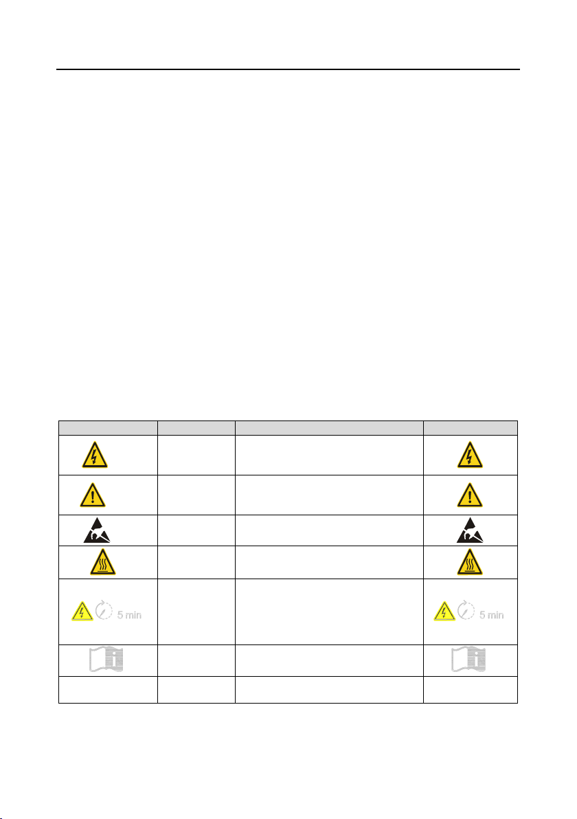
1.3 Warning symbols
Warnings caution you about conditions which can result in serious injury or death and/or damage to
the equipment, and advice on how to avoid said danger. The following warning symbols are used in
this manual:
Symbols
Name
Instruction
Abbreviation
Danger
Danger
Serious physical injury or even death
may occur if these requirements are not
followed.
Warning
Warning
Physical injury or damage to the
equipment may occur if these
requirements are not followed.
Forbid
Electrostatic
discharge
Damage to the PCBA board may occur if
these requirements are not followed.
Hot
Hot sides
The base of the VFD may become hot.
Do not touch.
Electric shock
As high voltage still presents in the bus
capacitor after power-off, wait at least five
minutes (or 15 min / 25 min, depending
on the warning symbols on the machine)
after power-off to prevent electric shock.
Read manual
Read the operation manual before
operating the equipment.
Note
Note
Procedures taken to ensure proper
operation.
Note

Frequency Inverter ST600 Series High-Performance Multifunction VFD Safety Precautions
-2-
1.4 Safety guidelines
⚫Only trained and qualified electricians are allowed to carry out related operations.
⚫Do not perform wiring, inspection or component replacement when a power supply is
connected. Ensure all the input power supplies are disconnected before wiring and
inspection, and wait for at least the time designated on the VFD or until the DC bus
voltage is less than 36V. The minimum waiting time is listed in the table below.
VFD model
Minimum waiting time
400V
1R5G3–110G3
5 min
400V
132G3–315G3
15 min
400V
355G3 and above
25 min
⚫Do not refit the VFD unless authorized; otherwise fire, electric shock or other injuries
may occur.
⚫The base of the radiator may become hot while running. Do not touch to avoid injury.
⚫The electrical parts and components inside the VFD are electrostatic. Take measures
to prevent electrostatic discharge during related operation.
1.4.1 Delivery and installation
⚫Install the VFD on fire-retardant material and keep the VFD away from combustible
materials.
⚫Connect the optional brake parts (brake resistors, brake units or feedback units)
according to the wiring diagram.
⚫Do not operate on a damaged or incomplete VFD.
⚫Do not touch the VFD with wet items or body parts; otherwise electric shock may occur.
Note:
⚫Select appropriate tools for delivery and installation to ensure safe and proper running of the VFD
and to avoid physical injury or death. To ensure physical safety, the installation staff should take
mechanical protective measures, such as wearing exposure shoes and working uniforms.
⚫Be sure to avoid physical shock or vibration during delivery and installation.
⚫Do not carry the VFD by its front cover only, as the cover may fall off.
⚫Installation site should be away from children and public places.
⚫The VFD should be used in proper environment (see section 4.2.1 "Installation environment" for
details).
⚫Prevent the screws, cables and other conductive parts from falling into the VFD.
⚫As leakage current of the VFD during running may exceed 3.5mA, ground properly and ensure
the grounding resistance is less than 10Ω. The conductivity of PE grounding conductor is the
same as that of the phase conductor. For models higher than 30 kW, the cross sectional area of
the PE grounding conductor can be slightly less than the recommended area.
⚫R, S and T are the power input terminals, and U, V and W are output motor terminals. Connect

Frequency Inverter ST600 Series High-Performance Multifunction VFD Safety Precautions
-3-
the input power cables and motor cables properly; otherwise damage to the VFD may occur.
1.4.2 Commissioning and running
⚫Disconnect all power sources applied to the VFD before terminal wiring, and wait for at
least the time designated on the VFD after disconnecting the power sources.
⚫High voltage presents inside the VFD while running. Do not carry out any operation on
the VFD while it is running except for keypad setup. It must be noted that the control
terminal of EV1000 inverter is an ELV (Extra Low Voltage) circuit, which cannot be
connected directly to the accessible terminals of other devices if no protective isolation
measure is taken. For instance, the RS485 terminal of the inverter can be connected to
RS232 interface of the PC only after a converter with protective isolation is connected
between them.
⚫The VFD may start up by itself when P01.21 (restart after power cut) is set to 1. Do not
get close to the VFD and motor.
⚫The VFD cannot be used as an "emergency-stop device".
⚫The VFD cannot act as an emergency brake for the motor; it is a must to install a
mechanical brake device.
⚫During driving permanent magnet synchronous motor, besides above-mentioned items,
the following work must be done before installation and maintenance.
1. Disconnect all input power sources including main power and control power.
2. Ensure that the permanent-magnet synchronous motor has been stopped, and that
the voltage on output end of the VFD is lower than 36V.
3. After the permanent-magnet synchronous motor is stopped, wait for at least the time
designated on the VFD, and ensure the voltage between "+" and "-" is lower than
36V.
4. During operation, it is a must to ensure the permanent-magnet synchronous motor
cannot run again by the action of external load; it is recommended to install an
effective external brake device or disconnect the direct electrical connection between
permanent-magnet synchronous motor and the VFD.
Note:
⚫Do not switch on or switch off input power sources of the VFD frequently.
⚫For VFDs that have been stored for a long time, set the capacitance and carry out inspection and
pilot run on the VFD before use.
⚫Close the front cover before running; otherwise electric shock may occur.
Frequency Inverter ST600 Series High-Performance Multifunction VFD Safety Precautions
-4-
1.4.3 Maintenance and component replacement
⚫Only well-trained and qualified professionals are allowed to perform maintenance,
inspection, and component replacement on the VFD.
⚫Disconnect all the power sources applied to the VFD before terminal wiring, and wait
for at least the time designated on the VFD after disconnecting the power sources.
⚫Take measures to prevent screws, cables and other conductive matters from falling into
the VFD during maintenance and component replacement.
Note:
⚫Use a proper torque to tighten the screws.
⚫Keep the VFD and its parts and components away from combustible materials during
maintenance and component replacement.
⚫Do not carry out insulation voltage-endurance test on the VFD, or measure the control circuits of
the VFD with megameter.
⚫Take proper anti-static measures on the VFD and its internal parts during maintenance and
component replacement.
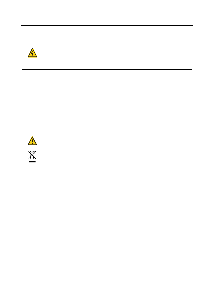
1.4.4 Scrap treatment
The heavy metals inside the VFD should be treated as industrial effluent.
When its life cycle ends, the product should enter the recycling system. Dispose of it
separately at an appropriate collection point instead of placing it in the normal waste stream.

Frequency Inverter ST600 Series High-Performance Multifunction VFD Precautions for Quick
Application
-5-
2 Precautions for Quick Application
2.1 What this chapter contains
This chapter introduces the basic principles required during installation commissioning. Users can
ensure quick installation commissioning by following these principles.
2.2 Unpack inspection
Check as follows after receiving products.
1. Check whether the packing box is damaged or dampened. If yes, contact local sellers or Sourcetronic
offices.
2. Check the model identifier on the exterior surface of the packing box is consistent with the purchased
model. If not, contact local sellers or Sourcetronic offices.
3. Check whether the interior surface of the packing box is improper, for example wet, or whether the
enclosure of the VFD is damaged or cracked. If yes, contact local sellers or Sourcetronic offices.
4. Check whether the nameplate of the VFD is consistent with the model identifier on the exterior surface
of the packing box. If not, contact local sellers or Sourcetronic offices.
5. Check whether the accessories (including user's manual, control keypad and expansion card units)
inside the packing box are complete. If not, contact local sellers or Sourcetronic offices.
2.3 Application confirmation
Check the following items before operating the VFD:
1. Verify the load mechanical type to be driven by the VFD, and check whether overload occurred to
the VFD during actual application, or whether the VFD power class needs to be enlarged.
2. Check whether the actual running current of load motor is less than rated VFD current.
3. Check whether the control precision required by the actual load is the same as the control precision
provided by the VFD.
4. Check whether the grid voltage is consistent with the rated VFD voltage.
5. Check whether the functions required need an optional expansion card to be available.
2.4 Environment confirmation
Check the following items before use:
1. Check whether the ambient temperature of the VFD during actual application exceeds 40°C, if yes,
derate 1% for every additional 1°C. In addition, do not use the VFD when the ambient temperature
exceeds 50°C.
Note: For a cabinet-type VFD, its ambient temperature is the air temperature inside the cabinet.

Frequency Inverter ST600 Series High-Performance Multifunction VFD Precautions for Quick
Application
-6-
2. Check whether ambient temperature of the VFD during actual application is below -10°C, if yes,
install a heating facility.
Note: For a cabinet-type VFD, its ambient temperature is the air temperature inside the cabinet.
3. Check whether the altitude of the application site exceeds 1000m. When the installation site altitude
exceeds 1000m, derate 1% for every increase of 100m; when the installation site altitude exceeds
3000m, consult the local Sourcetronic seller or office.
4. Check whether the humidity of the application site exceeds 90%, if yes, check whether condensation
occurred, if condensation does exist, take additional protective measures.
5. Check whether there is direct sunlight or the possibility of animal intrusion at the application site, if
yes, take additional protective measures.
6. Check whether there is dust, explosive or combustible gases at the application site, if yes, take
additional protective measures.
2.5 Installation confirmation
After the VFD is installed properly, check the installation condition of the VFD.
1. Check whether the input power cable and current-carrying capacity of the motor cable fulfill actual
load requirements.
2. Check whether peripheral accessories (including input reactors, input filters, output reactors, output
filters, DC reactors, brake units and brake resistors) of the VFD are all of the correct type and installed
properly; check whether the installation cables fulfill the requirements on current-carrying capacity.
3. Check whether the VFD is installed on fire-retardant materials; check whether the hot parts (reactors,
brake resistors, etc.) are kept away from combustible materials.
4. Check whether all the control cables are routed separately from power cables based on EMC
requirement.
5. Check whether all the grounding systems are grounded properly according to VFD requirements.
6. Check whether installation spacing of the VFD complies with the requirements in the operation
manual.
7. Check whether installation mode of the VFD complies with the requirements in the operation manual.
Vertical installation should be adopted whenever possible.
8. Check whether external connecting terminals of the VFD are firm and tight enough, and whether the
moment is up to the requirement.
9. Check whether there are redundant screws, cables or other conductive objects inside the VFD, if
yes, take them out.

Frequency Inverter ST600 Series High-Performance Multifunction VFD Precautions for Quick
Application
-7-
2.6 Basic commissioning
Carry out basic commissioning according to the following procedures before operating on the VFD.
1. Select motor type, set motor parameters and select VFD control mode according to actual motor
parameters.
2. If autotuning is needed: if possible, disconnect the motor load to carry out dynamic parameter
autotuning; if the load cannot be disconnected, perform static autotuning.
3. Adjust the acceleration and deceleration time based on actual working conditions of the load.
4. Jogging to carry out device commissioning. Check whether the motor running direction is consistent
with the direction required; if not, it is recommended to change the motor running direction by
exchanging the motor wiring of any two phases.
5. Set all the control parameters, and carry out actual operation.
2.7 Safety standard related data
IEC/EN 61508 (Class A system)
ISO 13849**
SIL
PFH
HFT
SFF
λdu
λdd
PTI*
PL
CCF
DC
Category
2
8.73x10⁻¹⁰
1
71.23%
1.79x10⁻⁹
0
1 year
d
57
60%
3
* PTI: Proof test interval
** Depends on the classification defined on the EN ISO 13849-1.
Frequency Inverter ST600 Series High-Performance Multifunction VFD Product Overview
-8-
3 Product Overview
3.1 What this chapter contains
This chapter mainly introduces the operation principles, product features, layouts, nameplates and
model instructions.
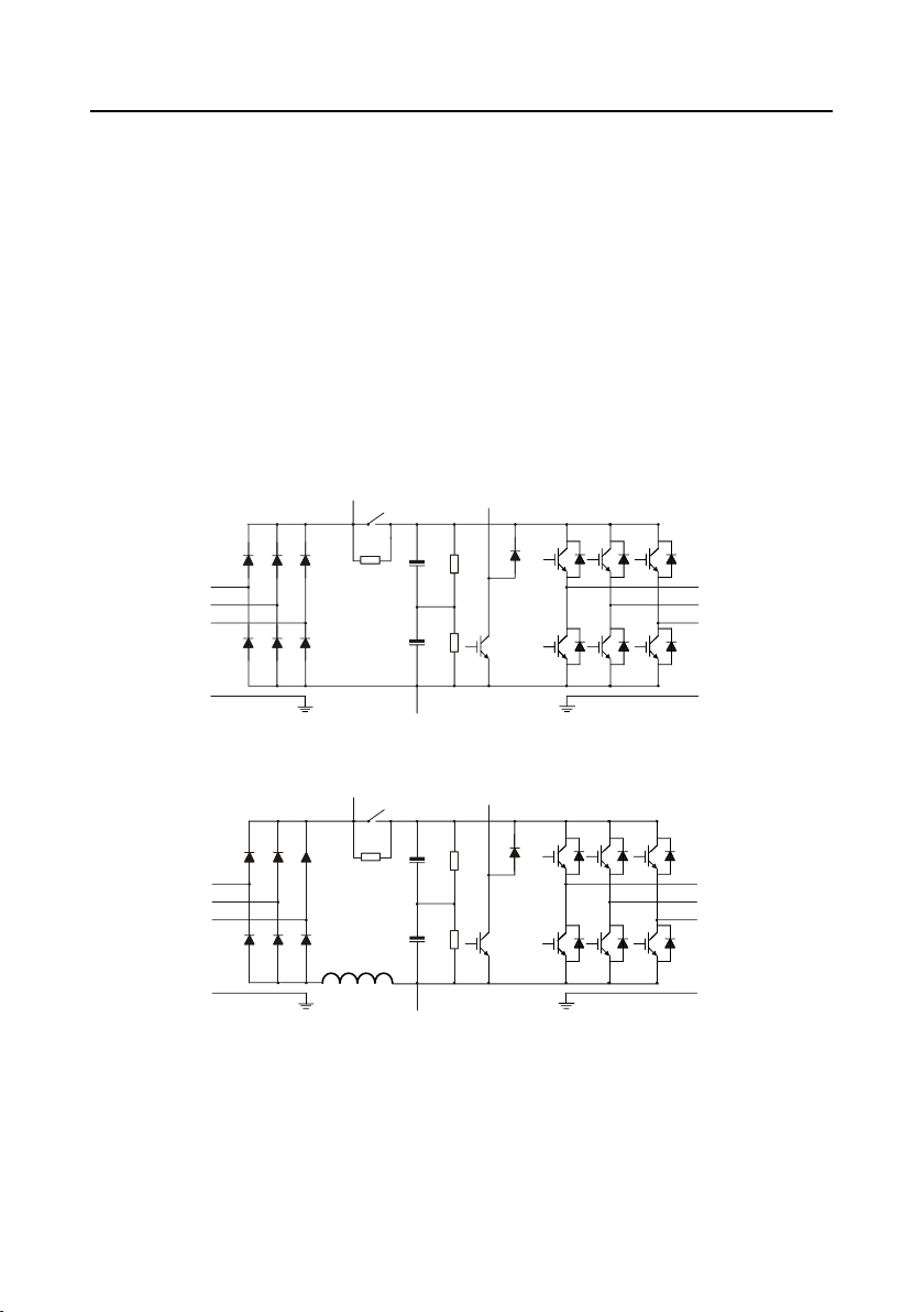
3.2 Basic principle
The frequency inverter ST600 high-performance multifunction VFD is used to control asynchronous
AC induction motor and permanent-magnet synchronous motor. The figure below shows the main
circuit diagram of the VFD. The rectifier converts 3PH AC voltage into DC voltage, and the capacitor
bank of intermediate circuit stabilizes the DC voltage. The inverter converts DC voltage into the AC
voltage used by AC motor. When the circuit voltage exceeds the maximum limit value, external brake
resistor will be connected to intermediate DC circuit to consume the feedback energy.
Figure 3-1 Main circuit diagram for standard and SP model VFDs 015G3 and below
R
S
T
U
V
W
(+)
(-)
PE PE
PB
Figure 3-2 Main circuit diagram for standard model VFDs 018G3–037G3
R
S
T
U
V
W
(+)
(-)
PE PE
PB

Frequency Inverter ST600 Series High-Performance Multifunction VFD Product Overview
-9-
Figure 3-3 Main circuit diagram for standard model VFDs 045G3–110G3
R
S
T
U
V
W
(+)
(-)
PE PE
Figure 3-4 Main circuit diagram for standard model VFDs 132G3 and above
R
S
T
U
V
W
(+)
(-)
DC reactor
P1
PE PE
Figure 3-5 Main circuit diagram for SP model VFDs 018G3–110G3
R
S
T
U
V
W
(+)
(-)
PE PE
PB
Note:
1. Standard model VFDs 132G3 and higher can be connected to external DC reactors. Before
connection, take off the copper bar between P1 and (+). Standard model VFDs 045G3 and higher
can be connected to external braking units. DC reactors and braking units are optional parts.
2. Standard model VFDs 018G3–110G3 are equipped with built-in DC reactors.
Frequency Inverter ST600 Series High-Performance Multifunction VFD Product Overview
-10-
3. Built-in brake units are included in the SP model VFDs and standard model VFDs 037G3 and below.
The models that carry built-in brake units can also be connected to external brake resistors. The
brake resistors are optional parts.
3.3 Product specification
Function description
Specification
Power input
Input voltage (V)
-4 model: 3PH 380V (-15%)–440V (+10%)
Input current (A)
Refer to section 3.6 Rated values.
Input frequency (Hz)
50Hz or 60Hz, allowable range: 47–63Hz
Power output
Output voltage (V)
0–input voltage
Output current (A)
Refer to section 3.6 Rated values.
Output power (kW)
Refer to section 3.6 Rated values.
Output frequency (Hz)
0–400Hz
Technical
control
performance
Control mode
Space voltage vector control, sensorless vector control (SVC),
and feedback vector control (FVC)
Motor type
Asynchronous motor, permanent-magnet synchronous motor
Speed regulation ratio
Asynchronous motor 1: 200 (SVC); Synchronous motor 1: 20
(SVC), 1:1000 (FVC)
Speed control precision
±0.2% (SVC), ±0.02% (FVC)
Speed fluctuation
± 0.3% (SVC)
Torque response
<20ms SVC) , <10ms (FVC)
Torque control precision
10% (SVC) , 5% (FVC)
Starting torque
Asynchronous motor: 0.25Hz/150% (SVC)
Synchronous motor: 2.5 Hz/150% (SVC)
0Hz/200% (FVC)
Overload capacity
150% of rated current: 1min;
180% of rated current: 10s;
200% of rated current: 1s;
Running
control
performance
Frequency setup mode
Digital, analog, pulse frequency, multi-step speed running,
simple PLC, PID, Modbus communication, PROFIBUS
communication, etc;
Realizes switch-over between the set combination and the set
channel
Automatic voltage
regulation function
Keeps the output voltage constant when grid voltage changes
Fault protection function
Provides over 30 kinds of fault protection functions, such as
overcurrent, overvoltage, undervoltage, over-temperature,
phase loss and overload, etc.
Speed tracking restart
function
Realize impact-free starting of the motor in rotating

Frequency Inverter ST600 Series High-Performance Multifunction VFD Product Overview
-11-
Retension at transient
voltage drop
Keeps running with regenerative energy when the grid
transiently drops.
Motor switchover
Supports two groups of motor parameters to control motor
switchover.
Peripheral
interface
Terminal analog input
resolution
No more than 20mV
Terminal digital input
resolution
No more than 2ms
Analog input
2 inputs, AI1: 0–10V/0–20mA; AI2: -10–10V
Analog output
1 output, AO1: 0–10V /0–20mA
Digital input
Four regular inputs; max. frequency: 1kHz; internal impedance:
3.3kΩ
Two high-speed inputs; max. frequency: 50kHz; supports
quadrature encoder input; with speed measurement function
Digital output
One high-speed pulse output; max. frequency: 50kHz
One Y terminal open collector output
Relay output
Two programmable relay outputs
RO1A NO, RO1B NC, RO1C common port
RO2A NO, RO2B NC, RO2C common port
Contact capacity: 3A/AC250V, 1A/DC30V
Extension interface
Three extension interfaces: SLOT1, SLOT2, SLOT3
Expandable PG card, programmable expansion card,
communication card, I/O card, etc
Others
Installation mode
Support wall-mounting and flange-mounting
Operation ambient
temperature
-10–50°C
Ingress protection
rating
IP20; IP55
Cooling mode
Forced-air cooling
Brake unit
Built-in brake units are included in all SP model VFDs.
EMC filter
Conducted emissions of all models meet the requirements of C3
in the IEC/EN 61800-3 standard. The -AS models offers the 30m
motor cable, meeting the C3 requirements.
External filter is optional: Conducted emission can meet the
requirements of C2 in the IEC/EN 61800-3 standard.
Note: It is required to observe the EMC compliance required by
the appendix of the manual. The motor and motor cables shall
be selected based on technical requirements specified in the
appendix of the manual.
STO certification level
Meet the SIL2 level
Frequency Inverter ST600 Series High-Performance Multifunction VFD Product Overview
-12-
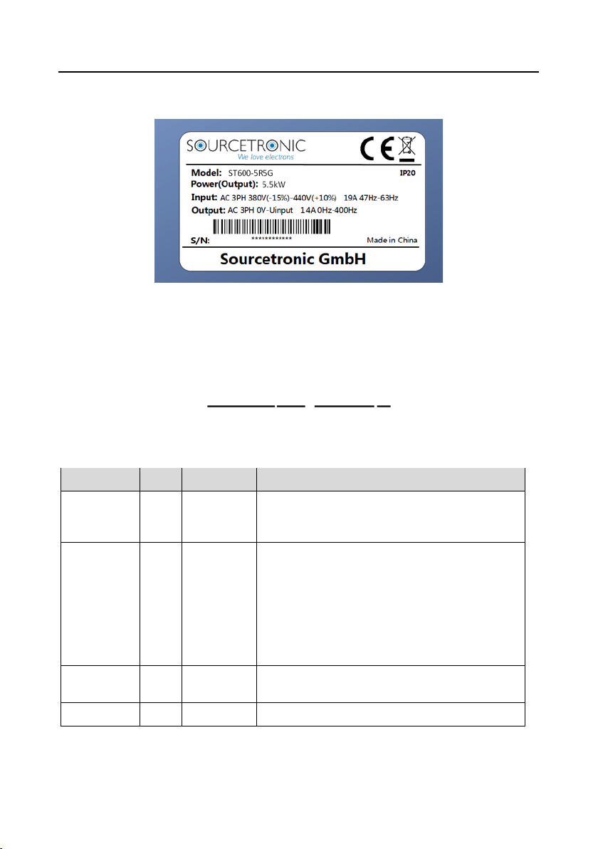
3.4 Product nameplate
Figure 3-6 Product nameplate
Note: This is an example of the nameplate of standard frequency inverter ST600 products. The
UKCA/CE/IP20/IP55 markings on the top right will be marked according to actual product model and
certification conditions.
3.5 Product model
Figure 3-7 Product model
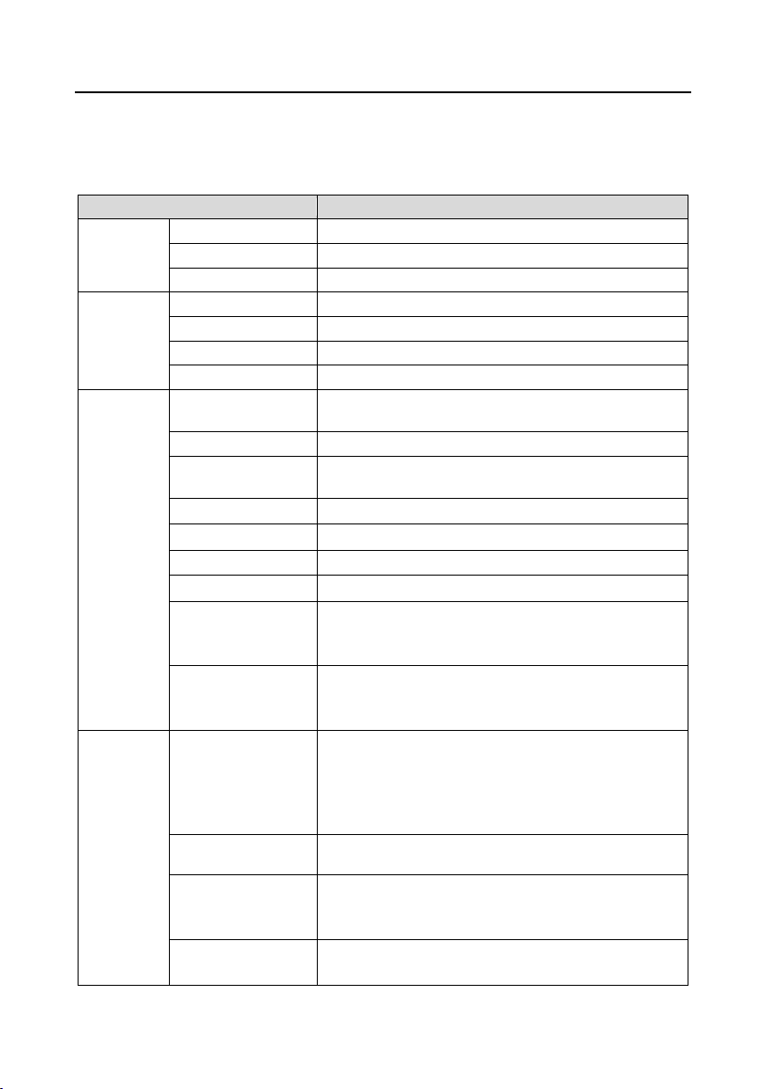
Table 3-1 Description of product models
Field
Sign
Description
Example
Product
category
①
Abbreviation
of product
series
ST600: frequency inverter ST600 high-performance multi-
function VFD
IP rating
②
Ingress
protection
rating
None: IP20 ingress protection rating (No protection
against dust nor water)
SP: IP55 ingress protection rating (It is impossible to
completely prevent dust from entering, but the amount of
dust from entering will not cause damage to the
equipment. It will not cause damage when the product
under normal installation state is immersed in water from
each direction).
Rated power
③
Power range
+ load type
5R5: 5.5kW
G: Constant torque load
Voltage level
④
Voltage level
3: AC 3PH 380V (-15%)–440V (+10%)
S T600SP 5R 5G 3-
① ② ③ ④

Frequency Inverter ST600 Series High-Performance Multifunction VFD Product Overview
-13-
3.6 Rated values
Table 3-2 Rated values of standard models
Frame
code
Product model
Output
power
(kW)
Input
current
(A)
Output
current
(A)
1
ST600-1R5G3
1.5
5.0
3.7
ST600-2R2G3
2.2
5.8
5
2
ST600-004G3
4
13.5
9.5
3
ST600-5R5G3
5.5
19.5
14
ST600-7R5G3
7.5
25
18.5
4
ST600-011G3
11
32
25
ST600-015G3
15
40
32
5
ST600-018G3
18.5
45
38
ST600-022G3
22
51
45
6
ST600-030G3
30
64
60
ST600-037G3
37
80
75
7
ST600-045G3
45
98
92
ST600-055G3
55
128
115
ST600-075G3
75
139
150
8
ST600-090G3
90
168
180
ST600-110G3
110
201
215
9
ST600-132G3
132
265
260
ST600-160G3
160
310
305
ST600-185G3
185
345
340
ST600-200G3
200
385
380
10
ST600-220G3
220
430
425
ST600-250G3
250
460
480
ST600-280G3
280
500
530
ST600-315G3
315
580
600
11
ST600-355G3
355
625
650
ST600-400G3
400
715
720
ST600-450G3
450
840
820
ST600-500G3
500
890
860
Other manuals for ST600 Series
1
This manual suits for next models
40
Table of contents
Other Sourcetronic Inverter manuals


Popular Inverter manuals by other brands

Zlpower
Zlpower IG500-12-C user manual

Samlex Europe
Samlex Europe SWI 3000-12 owner's manual

Carrier
Carrier ASPAS1CCA007 Specifications

Xantrex
Xantrex XPower 1500 owner's guide

Sandi Electric
Sandi Electric SDP-30KW User and installation manual

SolaX Power
SolaX Power X-Hybrid SK-BMU Quick installation guide


