manuals.online logo
Brands
  1. Home
  2. •
  3. Brands
  4. •
  5. Kuhne electronic
  6. •
  7. Inverter
  8. •
  9. Kuhne electronic MKU 57 G4 User manual

Kuhne electronic MKU 57 G4 User manual

Popular Inverter manuals by other brands

Omnik New Energy Omniksol-1.5k-TL user manual

Omnik New Energy

Omnik New Energy Omniksol-1.5k-TL user manual

Agilent Technologies 33250A user guide

Agilent Technologies

Agilent Technologies 33250A user guide

4-noks ZR-SWITCH-RC instruction manual

4-noks

4-noks ZR-SWITCH-RC instruction manual

V&T V5 Series user manual

V&T

V&T V5 Series user manual

Hon Turing HT-T-S1000-12 introduction

Hon Turing

Hon Turing HT-T-S1000-12 introduction

Metabo E 140 SP Plus Original operating instructions

Metabo

Metabo E 140 SP Plus Original operating instructions

BARRON EXITRONIX Tucson Micro Series installation instructions

BARRON

BARRON EXITRONIX Tucson Micro Series installation instructions

Baumer HUBNER TDP 0,2 Series Mounting and operating instructions

Baumer

Baumer HUBNER TDP 0,2 Series Mounting and operating instructions

electroil ITTPD11W-RS-BC Operation and Maintenance Handbook

electroil

electroil ITTPD11W-RS-BC Operation and Maintenance Handbook

Silicon Solar TPS555-1230 instruction manual

Silicon Solar

Silicon Solar TPS555-1230 instruction manual

Mission Critical Xantrex Freedom SW-RVC owner's guide

Mission Critical

Mission Critical Xantrex Freedom SW-RVC owner's guide

HP 3312A Operating and service manual

HP

HP 3312A Operating and service manual

Hoymiles HM-500T user manual

Hoymiles

Hoymiles HM-500T user manual

Nitecore SPM10 user manual

Nitecore

Nitecore SPM10 user manual

AEG Protect PV installation manual

AEG

AEG Protect PV installation manual

On Board TruePower Plus 1200MS owner's manual

On Board

On Board TruePower Plus 1200MS owner's manual

Plugreen PGM-200P-230 Installation and operation manual

Plugreen

Plugreen PGM-200P-230 Installation and operation manual

Fourgroup Easy use and Programming Handbook

Fourgroup

Fourgroup Easy use and Programming Handbook

manuals.online logo
manuals.online logoBrands
  • About & Mission
  • Contact us
  • Privacy Policy
  • Terms and Conditions

Copyright 2025 Manuals.Online. All Rights Reserved.

shop.kuhne-electronic.de
Kuhne electronic GmbH
Scheibenacker 3 Telefon: +49 (0) 9293 / 800640
95180 Berg –Germany E-Mail: info@kuhne-electronic.de Solutions for the wireless world
MKU 57 G4 - 6 cm Transverter
Seite / page 1
MKU 57 G4
Handbuch
Manual
16.04.2019
shop.kuhne-electronic.de
Kuhne electronic GmbH
Scheibenacker 3 Telefon: +49 (0) 9293 / 800640
95180 Berg –Germany E-Mail: info@kuhne-electronic.de Solutions for the wireless world
MKU 57 G4 - 6 cm Transverter
Seite / page 2
Technische Daten / Specification
HF Frequenzbereich 5760 … 5762 MHz
ZF Frequenzbereiche 144 … 146 MHz, 146 … 148 MHz, 432 … 434 MHz, 434 … 436 MHz
ZF Eingangsleistung 0,5 … 5 W, einstellbar
RX Verstärkung min. 20 dB
Rauschzahl @ 18 °C typ. 1,0 dB NF, max. 1,2 dB NF
TX-Ausgangsleistung min. 250 mW @ 25 °C
Die Monitorspannung beträgt ca. 1,0 V bei 250 mW Ausgangsleistung.
Nebenwellenunterdrückung min. 40 dB, typ. 50 dB
Oberwellenunterdrückung typ. 50 dB
LO-Genauigkeit @ 18 °C typ. +/- 0,5 ppm (ohne 10 MHz Referenzfrequenz)
LO-Frequenzstabilität (-5 ... +55 °C) typ. +/- 0,5 ppm (ohne 10 MHz Referenzfrequenz)
LO Umschaltbar 5616 MHz, 5614 MHz, 5328 MHz, 5326 MHz
Externer Referenzeingang 10 MHz / 2 … 10 mW (Sinus- oder Rechtecksignal), max. 2,0 Vss
Koaxanschluss Referenzeingang SMA-Buchse / 50 Ohm
PTT Steuerung Kontakt an Masse oder +12 V DC auf der ZF-Leitung
Versorgungsspannung +12 ... +14 V DC
Stromaufnahme typ. 300 mA (RX), typ. 800 mA (TX)
ZF-Anschlüsse / Impedanz SMA-Buchsen / 50 Ohm
HF-Anschlüsse / Impedanz SMA-Buchsen / 50 Ohm (RX/TX getrennt)
Stromversorgung und Steueranschlüsse Durchführungskondensatoren / 2,54 mm Stiftleisten
Gehäuse professionell gefrästes Aluminium
Abmessungen (mm) 175 x 63 x 36
Gewicht typ. 370 g
Maximale Gehäusetemperatur +55 °C
Zur Kühlung sollte der Transverter auf ein Chassisblech oder einen kleinen Kühlkörper montiert werden.
Die Gehäusetemperatur darf +55 °C nicht überschreiten.
Für den Betrieb der Hochfrequenzmodule sind die entsprechenden gesetzlichen Vorschriften zu beachten.
Diese Erzeugnisse dürfen nur an lizensierte Funkamateure oder andere EMV-fachkundige Betriebe verkauft werden.
CE Konformität EMC directive 2014/30/EU
Low voltage directive 2014/35/EU
RoHS directive 2011/65/EU
shop.kuhne-electronic.de
Kuhne electronic GmbH
Scheibenacker 3 Telefon: +49 (0) 9293 / 800640
95180 Berg –Germany E-Mail: info@kuhne-electronic.de Solutions for the wireless world
MKU 57 G4 - 6 cm Transverter
Seite / page 3
Technische Daten / Specification
RF frequency range 5760 … 5762 MHz
IF frequency ranges 144 … 146 MHz, 146 … 148 MHz, 432 … 434 MHz, 434 … 436 MHz
IF input power 0,5 … 5 W, adjustable
RX gain min. 20 dB
Noise figure @ 18 °C typ. 1.0 dB, max. 1.2 dB
TX output power min. 250 mW @ 25 °C
The typical monitor voltage at 250 mW is about 1.0 V.
Spurious rejection min. 40 dB, typ. 50 dB
Harmonic rejection typ. 50 dB
LO accuracy @ 18 °C typ. +/- 0.5 ppm (without 10 MHz external reference)
LO frequency stability (-5 ... +55 °C) typ. +/- 0.5 ppm (without 10 MHz external reference)
LO switchable 5616 MHz, 5614 MHz, 5328 MHz, 5326 MHz
External reference input 10 MHz / 2 ... 10 mW (sine or square wave), max. 2.0 Vpp
Reference input connector SMA-female / 50 ohms
PTT control contact closure to ground or +12 V on the IF-cable
Supply voltage +12 ... +14 V DC
Current consumption typ. 300 mA (RX), typ. 800 mA (TX)
IF connectors / impedance SMA-female / 50 Ohms
RF connectors / impedance SMA-female / 50 ohms (separate RX/TX connectors)
Supply and control connectors Feedthrough capacitor / 2,54 mm pin header
Case professional milled aluminium
Dimensions (mm) 175 x 63 x 36
Weight typ. 370 g
Maximum case temperature +55 °C
The transverter should be mounted on a chassis or a small heat sink. The case temperature must not exceed +55 °C.
Products are only to be sold to radio amateurs with a licence or to competent companies.
For operating high frequency modules legal instructions must be followed.
CE Conformity EMC directive 2014/30/EU
Low voltage directive 2014/35/EU
RoHS directive 2011/65/EU
Test certificate 144 … 148 MHz IF 432 … 436 MHz IF
RX gain ________________ dB RX gain _______________ dB
Noise figure ____________ dB Noise figure ___________ dB
TX output power ________ mW TX output power _______ mW
________________ ________________
QS Sig.
shop.kuhne-electronic.de
Kuhne electronic GmbH
Scheibenacker 3 Telefon: +49 (0) 9293 / 800640
95180 Berg –Germany E-Mail: info@kuhne-electronic.de Solutions for the wireless world
MKU 57 G4 - 6 cm Transverter
Seite / page 4
Anschlüsse / Connectors
RX-Verstärkung
RX gain
TX-Verstärkung
TX gain
+
+-
-
MON
OUT
+TX
OUT
PTT
man.
+12 V DC
TX
OUT
RX
IN
IF
EXT. 10 MHz
REF. IN
2 … 10 mW
LOCK DETECT
OUT
JP 3
JP 2
JP 1
shop.kuhne-electronic.de
Kuhne electronic GmbH
Scheibenacker 3 Telefon: +49 (0) 9293 / 800640
95180 Berg –Germany E-Mail: info@kuhne-electronic.de Solutions for the wireless world
MKU 57 G4 - 6 cm Transverter
Seite / page 5
Anschlüsse / Connectors
LO Abstimmung
LO adjust
+-
shop.kuhne-electronic.de
Kuhne electronic GmbH
Scheibenacker 3 Telefon: +49 (0) 9293 / 800640
95180 Berg –Germany E-Mail: info@kuhne-electronic.de Solutions for the wireless world
MKU 57 G4 - 6 cm Transverter
Seite / page 6
Pinbeschreibung / PIN description
+TX OUT
Schaltausgang / switched output
Der Anschlusspin „+TX OUT“ wird beim Senden über einen MOSFET (max. 0.4 A) an +12 V geschaltet. Der Ausgang kann zum
Schalten eines externen 12 V Antennenrelais verwendet werden. Dieser Ausgang ist mit einer selbstrückstellenden 500 mA
Halbleitersicherung abgesichert.
During transmit mode „+TX OUT“ is switched to +12 V via a MOSFET (max. 0.4 A). This output signal can be used to switch an
external antenna relay at the antenna. The output is protected with a self resetting 500 mA semiconductor fuse.
PTT man.
PTT Eingang / PTT input
Dieser Anschluss ist zum Senden an Masse zu schalten.
For transmit this pin must be switched to ground.
MON OUT
Monitor Ausgang / monitor output
Dieser Ausgang ist zum Überwachen der Transverterausgangsleistung (DC-Spannung). Die Spannung am MON Pin steigt mit
zunehmender Transverterausgangsleistung an. Die Spannung ist zum überwachen der Ausgangsleistung bestimmt, nicht für
exakte Messungen.
Output which monitors transverter output power (DC voltage). The MON pin voltage is getting higher with increasing transverter
output power. It is intended for observing the output power, not for exact measurements.
LOCK DETECT OUT
PLL lock detect
Dieser Ausgang schaltet gegen Masse (open Kollektor) wenn der interne Quarzoszillator auf die externe Referenzfrequenz
gerastet hat. Zur Strombegrenzung ist ein 330 Ohm Längswiderstand eingebaut.
This output switches to ground (open collector) as soon as the internal crystal oscillator of the transverter is locked to the
external reference frequency. A serial 330 ohm resistor limits the output current of this pin.
+12V DC
+12 ... +14 V DC
Versorgungsspannungseingang +12 ... +14 V DC.
Power supply input +12 … +14 V DC .
Gehäuse / Case
Masse / ground
shop.kuhne-electronic.de
Kuhne electronic GmbH
Scheibenacker 3 Telefon: +49 (0) 9293 / 800640
95180 Berg –Germany E-Mail: info@kuhne-electronic.de Solutions for the wireless world
MKU 57 G4 - 6 cm Transverter
Seite / page 7
Pinbeschreibung / PIN description
IF Konfiguration / IF config
JP 1
open
JP 1
bridged
5616 MHz LO
144 … 146 MHz
5614 MHz LO
146 … 148 MHz
5328 MHz LO
432 … 434 MHz
5326 MHz LO
434 … 436 MHz
JP 3
open
JP 3
bridged
JP 1, JP 2, JP 3 - LO / IF config
LO / ZF Einstellungen / LO / IF config
Die Jumper JP 1 bis JP 3 sind zur Wahl der Oszillatorfrequenz und somit zur Wahl des ZF-Bereichs des Transverters.
Mit JP 1 wird die Oszillatorfrequenz um 2 MHz verschoben.
Ist JP 1 offen ist der ZF-Bereich 144 … 146 MHz oder der ZF-Bereich 432 … 434 MHz gewählt.
Ist JP 1 geschlossen ist der ZF-Bereich 146 … 148 MHz oder ist der ZF-Bereich 434 … 436 MHz gewählt.
Mit JP 3 wird der ZF Bereich des Transverters gewählt (144 MHz oder 432 MHz).
Ist JP 3 offen ist der ZF-Bereich 144 … 146 MHz oder der ZF-Bereich 146 … 148 MHz gewählt.
Ist JP 3 geschlossen der ZF-Bereich 432 … 434 MHz oder der ZF-Bereich 434 … 436 MHz gewählt.
JP 2 hat keine Funktion.
With JP 1,2 and 3 the user can configure the oscillator frequenz of the transverter and so the IF range of the transverter.
JP 1 causes a oscillator frequency shift of 2 MHz.
If JP 1 is open the IF range 144 … 146 MHz or the IF range 432 … 434 MHz is selected.
If JP 1 is bridged the IF range 146 … 148 MHz or the IF range 434 … 436 MHz is selected.
With JP 3 the user can select the IF range of the transverter (144 MHz or 432 MHz).
If JP 3 is open the IF range 144 … 146 MHz or the IF range 146 … 148 MHz is selected.
If JP 3 is bridged the IF range 432 … 434 MHz or the IF range 434 … 436 MHz is selected.
JP 2 has no function.
shop.kuhne-electronic.de
Kuhne electronic GmbH
Scheibenacker 3 Telefon: +49 (0) 9293 / 800640
95180 Berg –Germany E-Mail: info@kuhne-electronic.de Solutions for the wireless world
MKU 57 G4 - 6 cm Transverter
Seite / page 8
Pinbeschreibung / PIN description
SEQ 1
antenna
coaxial relay
+ 12 … 28 V
MON
+ 12 V
+D
PA
LNA
TX
IF
RX
MKU Transverter
PTT
FUSE
+ 12 V
144 MHz (432 MHz)
IF
e.g. FT 290
FUSE
IN PA
Sequence
Controller
SEQ
FUSE
+ 12 V to coaxial relay
+ 12 V for TX
Viele Koaxrelais haben während des Umschaltvorganges eine zu geringe Entkopplung zwischen Sende-
und Empfangskontakt. Dies kann zur Zerstörung des Eingangstransistors im Konverter oder des
Vorverstärkers führen. Das Relais sollte eine Entkopplung von 50 dB erreichen.
Die Leistung auf den RX - Eingang darf 1 mW nicht überschreiten.
Es wird dringend die Verwendung einer Sequenzsteuerung empfohlen.
Achtung!
Many coaxial relays have too small isolation during the changeover between the transmitting and
receiving ports, which can lead to the destruction of the input transistor in the converter or the LNA.
The relay should achieve an isolation of approx 50 dB.
The power at the RX input must not exceed 1 mW.
We strongly recommend that a sequence controller should be used.
Attention!
SEQ 4
shop.kuhne-electronic.de
Kuhne electronic GmbH
Scheibenacker 3 Telefon: +49 (0) 9293 / 800640
95180 Berg –Germany E-Mail: info@kuhne-electronic.de Solutions for the wireless world
MKU 57 G4 - 6 cm Transverter
Seite / page 9
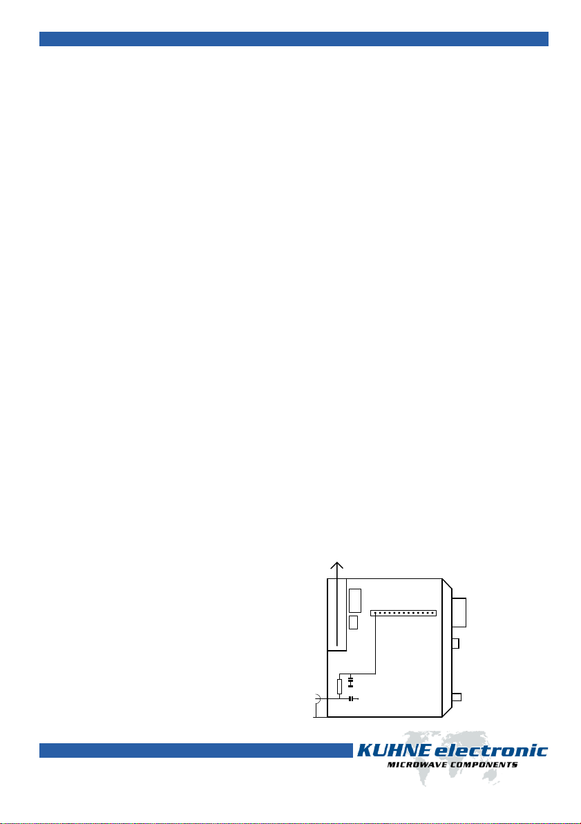
Sende - Empfangsumschaltung / RX-TX switching
4K7
1nF
1nF
144 MHz
RX - TX
T +9 V DC Steckerleiste
Connector
IC202
Umbau des IC-202 auf RX/TX - Umschaltung.
Modification of RX-TX switching in the ICOM IC-202
To switch a DB6NT microwave transverter from receive (RX) to transmit (TX), there are two possibilities: Either the port “PTT“
of the transverter is switched to ground for TX. Or a DC voltage of +3 … 12 V DC is fead to the inner conductor of the IF cable
for TX. This method saves an additional PTT cable between transverter and transceiver.
A suitable control circuit is already included in the transceivers YAESU FT-290R (old model) and ICOM IC-402. These
transceivers provide +12 V DC on the coaxial output connector at TX.
The YAESU FT-290RII (new model) does not provide this function, but it can be modified. The modification is described on
G4DDK’s homepage: www.g4ddk.com/Techstuff
ATTENTION! The ICOM IC-202 provides +12 V DC at RX! So when you connect a DB6NT transverter to a IC-202, then the
transverter will switch to TX. Therefore, a small modification is necessary (see picture below). With this modification the IC-202
will provide +12 V DC at TX.
The YAESU FT-817 must also be modified for transverter operation. Peter Vogl, DL1RQ, has written a small tutorial, how to do
this modification: www.bergtag.de/technik_18. A further descripton for the YAESU FT-817 is written by Pedro M.J. Wyns,
ON7WP. This description is published on our website: www.kuhne-electronic.de/en.
Um DB6NT - Mikrowellentransverter vom Empfang (RX) auf Senden (TX) umzuschalten, sind zwei Möglichkeiten vorgesehen:
Zum Einen besitzen die Transverter einen PTT - Anschluss, der bei Sendebetrieb über einen Kontakt nach Masse zu schalten ist.
Zum Anderen ist eine Umschaltmöglichkeit über das ZF - Kabel vorgesehen. Dazu ist im Sendefall eine Spannung zwischen +3 …
12 V DC auf den Innenleiter der ZF - Buchse zu schalten. Dies erspart eine zusätzliche Verbindungsleitung zwischen Transverter
und Transceiver.
Bei den Transceivern YAESU FT-290R (altes Modell) und ICOM IC-402 ist eine geeignete Umschaltsteuerrung bereits eingebaut.
Im YAESU FT290RII muss die Schaltung nachträglich eingebaut werden. Eine Bauanleitung wurde von Sam G4DDK beschrieben.
Sie ist auf seiner Homepage abrufbar unter www.g4ddk.com/Techstuff
Bei dem Transceiver ICOM IC-202 ist die benötigte Steuerung invers eingebaut. Bei Empfang werden +12 V DC am Ausgang
geliefert. Das heißt, wenn der Transceiver auf Empfang ist und an einen Transverter angeschlossen wird, dann schaltet dieser
auf Senden! Daher ist eine kleine Änderung im IC-202 notwendig.
Für den Transverterbetrieb mit dem YAESU FT-817 hat Peter Vogl, DL1RQ eine Umbauanleitung verfasst. Sie ist im Internet
abrufbar unter: www.bergtag.de/technik_18. Eine weitere Umbauanleitung für den YAESU FT-817 gibt es von Pedro M.J. Wyns,
ON7WP.
Sie kann auf unserer Homepage nachgelesen werden unter: www.kuhne-electronic.de
shop.kuhne-electronic.de
Kuhne electronic GmbH
Scheibenacker 3 Telefon: +49 (0) 9293 / 800640
95180 Berg –Germany E-Mail: info@kuhne-electronic.de Solutions for the wireless world
MKU 57 G4 - 6 cm Transverter
Seite / page 10
10 MHz Referenzeingang /10 MHz reference input
Es besteht die Möglichkeit den Transverter an ein 10 MHz Frequenznormal (Referenzfrequenz) anzuschließen. Wird eine
externe 10 MHz-Quelle angeschlossen, so wird automatisch auf PLL-Betrieb umgeschaltet. Die Frequenzstabilität ist nun von
der Referenzfrequenz abhängig.
10 MHz können von hoch stabilen OCXOs, Referenzoszillatoren von Frequenzzählern, Rubidium-Frequenznormalen oder GPS-
gesteuerten Referenzquellen eingespeist werden. Die externe Referenzquelle muss eine Ausgangsleistung von 2 bis 10 mW an
50 Ohm liefern.
Steht keine 10 MHz Referenzfrequenz zur Verfügung arbeitet der Transverter mit der Frequenzstabilität des eingebauten
Quarzoszillators.
An external 10 MHz reference frequency can be connected to the transverter to achieve highest frequency accuracy. When an
external 10 MHz source is connected to the transverter, the internal PLL will automatically be activated. Then, the frequency
stability depends only on the reference frequency.
The frequency of 10 MHz can be supplied by a highly stable OCXO, a reference oscillator of a frequency counter, a rubidium
frequency standard or a GPS controlled frequency source. The output power range of the external reference source must be in
the range from 2 to 10 mW on a 50 ohms load.
If no 10 MHz reference frequency is available the transverter works with the frequency stability of the built-in crystal oscillator.