12.
Commissioning
11.
Instruments
UNO-DM-6.0-TL-PLUS-Q-Quick Installation Guide EN-RevA
EFFECTIVE 26-10-2018
© Copyright 2018 ABB. All Rights Reserved.
Specications and illustrations subject to change without notice.
9.
Line cable and protective devices
10.
Output connection (AC)
→
Commissioning
→
Features and Technical Data
13.
Features and Technical Data
Protection switch under load (AC switch) and sizing of the line cable
To protect the AC connection line of the inverter, we recommend the installation of a protection device against overcurrent and earth leakages with the following
features:
UNO-DM-6.0-TL-PLUS
Type Circuit breaker with differential magnetic-thermal protection
Nominal voltage 230 Vac
Nominal current 40.0 A
Magnetic protection feature B/C
Number of poles 2
Type of differential protection A/AC
Differential sensitivity 300 mA
ABB declares that the ABB high frequency inverter without a transformer are not manufactured to inject continuous currents of ground fault, and therefore, the
differential installed downstream of the inverter, type B according to IEC 60755/A 2, is not required.
Characteristics and sizing of the line cable
The cable should be three-pole. The section of the AC line conductor must be sized in order to avoid
unwanted disconnections of the inverter from the distribution network due to high impedances of the
line that connects the inverter to the point of supply of electricity.
Line conductor cross-section Maximum length of the line conductor (m)
4 mm28 m
6 mm212 m
10 mm220 m
16 mm230 m
The values are calculated in nominal power condition considering:
1. a power loss along the line of not more than 1%.
2. copper cable used, with HEPR rubber insulation and placed in open air
Contact us
www.abb.com/solarinverters
The LEDs allow you to view inverter status conditions to be analyzed in greater depth by consulting the manual.
LEDs
06
POWER
Green Solid when the inverter is working correctly. Flashes when checking the grid or if
there is insufcient sunlight.
COMM Green
Activation status of the inverter’s wireless communication
ALARM Yellow The inverter has detected an anomaly. The anomaly is shown on the
“EVENTS” section of the internal webserver and on the display.
WLAN Multicolor Quality of the wireless communication signal.
GFI Red Ground fault on the DC side of the PV generator. The error is shown on the
“EVENTS” section of the internal webserver and on the display.
UNO-DM-6.0-TL-PLUS-Q
Input
Absolute maximum input voltage (Vmax,abs)600 V
Input activation voltage (Vstart)200 V
(adj. 120...350V)
DC input voltage operating range (Vdcmin...Vdcmax)0.7xVstart...580 V (min 90 V)
Rated input DC voltage (Vdcr)360 V
Rated input DC power (Pdcr) 6200 W
Number of independent MPPTs 2
Maximum Input power for each MPPT (PMPPTmax)MPPT1: 4000 W / MPPT2: 3500W
DC input voltage range (VMPPT min ... VMPPT max) with parallel conguration of
MPPT at Pacr 200...480 V
Numbe DC power limitation with parallel conguration of MPPT
Linear derating from Max to 500W [480V≤VMPPT≤580V]
DC power limitation for each MPPT with independent conguration of MPPT
at Pacr , max unbalance example (2)
MPPT1: 4000 W [200V≤VMPPT≤480V]
MPPT2: Pdcr-4000W [195V≤VMPPT≤480V] o 3500W [305V≤VMPPT≤480V] with no power
on MPPT1
Maximum DC input current (Idc max) / for each MPPT (IMPPTmax)31.5 A / 20.0 (IN1) -11.5A (IN2)
Maximum return current (AC side vs DC side) < 5 mA (In the event of a fault, limited by the external protection on the AC circuit)
Maximum short circuit current (Isc max) / for each MPPT 50.0 A / 25.0 A
Number of input DC connection 2 (IN1) / 1 (IN2)
DC connection type Quick t PV connector (1)
Type of PV panels connected in input in accordance with Standard IEC 61730 Class A
Input protection
Reverse polarity protection Yes, from a current limited source
Input overvoltage protection for each MPPT- Varistors Yes
Photovoltaic array insulation control According to local standard
DC disconnect switch characteristics (version with DC disconnect switch) 600 V / 25.0 A
N
L
Max 16 mm²
x:
18 mm
Ø13÷21mm
x
UNO-DM-6.0-TL-PLUS-Q
Output
AC connection type Single phase
Nominal output AC power (Pacr@cosφ=1) 6000 W
Maximum output AC power (Pac max@cosφ=1) 6000 W
Maximum apparent power (Smax)6650 VA
Nominal output AC voltage (Vacr)230 V
Output AC voltage range (Vacmin...Vacmax)180...264 Vac (3)
Maximum AC output current (Iac max)30.0 A
Maximum fault current
<40 A rms (100 ms)
Short circuit current contribution 40.0 A
Inrush current Negligible
Nominal output frequency (fr) 50 / 60 Hz (4)
Output frequency range (fmin...fmax) 47...53 / 57...63 Hz (4)
Nominal power factor and adjustability interval > 0.995; 0.1 – 1 Over/Under excited
Total harmonic current distortion < 3.5%
AC connections type
Screw terminal block, Cable Gland M32
Output Protection
Anti-islanding protection According to local standard
Maximum external AC overcurrent protection 40.0 A
Output overvoltage protection - Varistor 2 (L - N / L - PE)
Operational Performances
Maximum efciency (η
max
)97.4%
Weighted efciency (EURO/CEC) 97.0% / -
Power threshold of the power 8.0 W
Nighttime consumption < 0.4 W
Communication
Embedded Communication Interface Wireless (5)
Embedded Communication Protocol ModBus TCP (SunSpec)
Commissioning tool Web user interface, Aurora Manager Lite
Firmware Update Capabilities Locally and remotely
Monitoring Plant Portfolio Manager, Plant Viewer, Plant Viewer for Mobile (7)
Optional board UNO-DM-COM kit
Optional Communication Interface RS485 (use with meter for dynamic feed-in control), Alarm/Load manager relay,
Remote ON/OFF
Optional Communication protocol ModBus RTU (SunSpec), Aurora Protocol
Optional board UNO-DM-PLUS Ethernet COM kit
Optional Communication Interface Ethernet, RS485 (use with meter for dynamic feed-in control), Alarm/Load manager relay,
Remote ON/OFF
Optional Communication protocol ModBus TCP (SunSpec), ModBus RTU (SunSpec), Aurora Protocol
Environmental
Ambient temperature range -25...+60°C /-13...140°F
Ambient temperature derating above
45°C/113°F
Relative humidity 0...100% condensing
Typical noise emission pressure < 50 dB(A) @ 1 m (10)
Maximum operating altitude without derating 2000 m/6560 ft
Classication of environmental pollution degree for the external environment 3
Environmental category Outdoor
Physical
Environmental protection degree IP 65
Cooling system Natural
Dimensions (H x W x D) 418 mm x 553 mm x 180 mm/16.5” x 21.8” x 7.1”
Weight 20.5 kg / 45.2 lb
Mounting system Wall brackets
Overvoltage category in conformity with IEC 62109-1 II (DC input) III (AC output)
Safety
Isolation level Transformerless (TL)
Certications CE, RCM
Safety class I
Safety and EMC standard EN 50178, IEC/EN 62109-1, IEC/EN 62109-2, AS/NZS 3100, EN 61000-6-1, EN 61000-6-3,
EN 61000-3-11, EN 61000-3-12
Grid standard (9) (check your sales channel for availability) CEI 0-21, DIN V VDE V 0126-1-1, G59/3, EN 50438 (not for all national appendices), RD
1699, ITC-BT-40, AS 4777, C10/11, IEC 61727, IEC 62116
1. Refer to the document “String inverter – Product Manual appendix” available at www.abb.com/solarinverters to know the brand and the model of the quick t connector.
2.
Functionality with unbalanced channels
3. The AC voltage range may vary depending on specic country grid standard.
4. The Frequency range may vary depending on specic country grid standard. CE, 50Hz only.
5. As per IEEE 802.11 b/g/n standard.
7. Plant Viewer per Mobile availble remotely only, not for local commissioning.
9. Further grid standard will be added, please refer to ABB Solar page for further details.
10. @ Pure sine wave condition.
Note. The features that are not specically mentioned in this data sheet are not included in the product
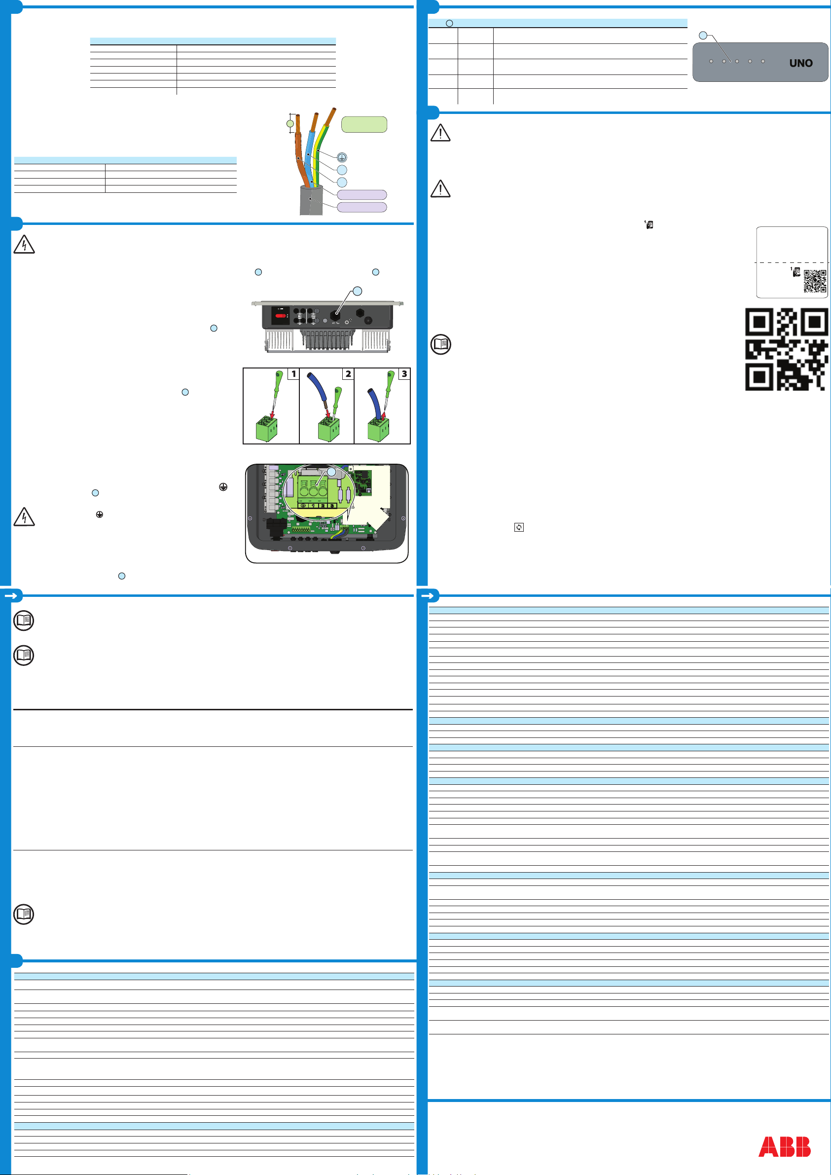
Caution! Before performing the operations described below, make sure that you have properly disconnected the AC line downstream of
the inverter!
For the grid connection of the inverter, 3 connections are needed: ground, neutral and phase. In any case, the earth connection of the inverter is mandatory.
The connection of the network cable to the inverter is performed by means of the AC cable gland
10
and the dedicated AC output terminal block
13
, by doing
the following:
- Strip 18 mm of sheathing from the AC grid connection cables
- Plug the AC line cable into the inverter, passing it through the AC cable gland
10
The procedure for opening the contacts of AC output terminal block
13
and tightening
cables is as follows:
1) Insert a at screwdriver in the slot behind the contacts until the clamp opens.
2) Insert the cable in the clamp with the screwdriver inserted in the slot.
3) Remove the screwdriver and check the tightness.
- Connect the protective earth (yellow-green) cable to the contact labelled with the
symbol on the terminal block
13
Warning! ABB inverters should be earthed (PE) via the terminal with the
protective earth label , using a cable with an appropriate cross-section
of the conductor for the maximum ground fault current that the generating
system might experience
- Connect the neutral cable (normally blue) to the terminal labelled with the number 1
- Connect the phase cable to the terminal labelled with the number 2
Once the connection to the terminal block
13
is complete, screw in the cable gland rmly (tightening torque 5.0Nm) and check the tightness.
POWER COMM ALARM WLAN GFI
06
- Click on “Next” button to proceed to the next stage of the conguration wizard.
The IP address assigned may vary for reasons connected to the wireless home router setup (for example, a very brief DHCP lease time). If
verication of the address is required, it is usually possible to obtain the client list (and the corresponding IP addresses) from the wireless
router administration panel.
If the inverter loses the connection with the home wireless network, it is available accessing the Wi-Fi network ABB-XX-XX-XX-XX-XX-XX, where “X” is an hexadeci-
mal number of the MAC Address.
The most common causes of losing connectivity might be: different wireless network password, faulty or unreachable router, replacement of
router (different SSID) without the necessary setting updates.
• STEP 3 - Date, Time and Time zone
- Set the Date, Time and Time zone (The inverter will propose these elds when available).
When it’s not possible for the inverter to detect the time protocol, these elds have to be manually entered.
- Click on “Next” button to proceed to the next stage of the conguration wizard.
• STEP 4 - Inverter country standard, Input mode, Meter and Energy policy.
Country standard
Set the grid standard of the country in
which the inverter is installed.
Input mode
- Indipendent
- Parallel
Meter
None (installation without meter)
REACT-MTR-1PH (single-phase)
ABB 3PH (three-phase)
ABB 1PH (single-phase)
Energy Policy
Zero injection
Self consumption
Custom
From the moment that the grid standard
is set, you have 24 hours to make any
changes to the value, after which the
“Country Select > Set Std.” functionality
is blocked, and the remaining time will
have to be reset in order to have the
24 hours of operation available again
in which to select a new grid standard
(follow the procedure “Resetting the re-
maining time for grid standard variation”
described in the relevant section).
See the relevant section of this guide
to know how to physically set the input
mode
If the selected meter is three-phase addi-
tional requested elds will appear:
- Meter Phase: select the phase to which
the inverter is connected.
When a meter type is selected is possible
to set also the Energy Policy elds that
allows to manage the energy produced
by the PV plant.
- Zero injection: The system automatically
manages power ows in order to avoid
the injection of energy to the grid.
- Self consumption: The system automat-
ically manages power ows in order to
maximise self-consumption.
- Custom: The system automatically
manages power ows in order to avoid
feeding the grid with power greater
than: PDC x Plim where PDC is the
power of the photovoltaic generator
(“PV GENERATOR POWER” param-
eter) and Plim is the output power limit
with respect to PDC(%) (“FEED-IN
POWER” parameter).
- Conrm the settings by clicking “DONE” and the inverter will test the meter and the battery working and it will reboot at the nish of test phase.
-
After the wizard is completed, the system will power-on. The inverter checks the grid voltage, measures the insulation resistance of the photovoltaic eld with
respect to ground and performs other auto-diagnostic checks. During the preliminary checks on the parallel connection with the grid, the “Power” LED keeps
ashing, the “Alarm” and “GFI” LEDs are off.
If the outcome of the preliminary checks on the grid parallel is positive, the inverter connects to the grid and starts to export power to the grid. The “Power” LED
remains xed on while the “Alarm” and “GFI” LEDs are off.
To address any problems that may occur during the initial stages of operation of the system and to ensure the inverter remains fully functional,
you are advised to check for any rmware updates in the download area of the website www.abb.com/solarinverters or at https://registration.
abbsolarinverters.com (instructions for registering on the website and updating the rmware are given in this manual).
Before proceeding with commissioning, make sure you have carried out all the following checks:
-Check the correct connection and polarity of the DC inputs, and the correct connection of the AC output and ground cables.
-Check the sealing barrier of the cable ducts and installed quick-t connectors to prevent accidental disconnections and/or
avoid compromising the IP65 environmental protection rating.
Commissioning is carried out via Wi-Fi connection to the inverter web user inteface. Initial setup must therefore be carried out via a tablet, notebook or smartphone
with a Wi-Fi connection.
To establish the connection and operate with the inverter, it is necessary to connect its input to the DC voltage of the photovoltaic panels.
•Supply the inverter with DC input voltage from the photovoltaic generator and via AC GRID voltage.
Make sure that the irradiation is stable and adequate for the inverter commissioning procedure to be completed.
• Pre-commissionig phase 1 - Connection to the local Wi-Fi network
- DEVICE USED TABLET/SMARTPHONE.
Once powered, launch a QR reader for mobile and SCAN the QR code marked with on the label on the right side of the inverter and connect to inverter
network (tap connect).
The name of the Wi-Fi network created by the system, that the connection should be established with, will be:
ABB-XX-XX-XX-XX-XX-XX (where the X is the MAC address)
After this step wait 10 seconds to allow the WLAN connection
- DEVICE USED LAPTOP.
Enable the wireless on the device you are using for the commissioning and search for the network named ABB-XX-XX-XX-XX-
XX-XX, where “X” is an hexadecimal number of the MAC Address (the MAC Address is indicated on the “wireless identication
label” on the side of the inverter).
When prompted, type the PK (product key), including the dashes. Example: 1234-1234-1234-1234 as the network password.
• Pre-commissionig phase 2 - Internal web UI access
- DEVICE USED TABLET/SMARTPHONE.
SCAN this QR code (it is also reported in the inverter pre-commissioning yer inside the box of the inverter). An internet
browser page showing the step by step procedure will be open.
The information contained in this QR code is the IP address of the web user interface of the inverter:
http://192.168.117.1
Recommended browsers: Chrome from v.55, Firefox from v.50, Safari from V.10.2.1
- DEVICE USED LAPTOP.
Open an internet browser page and insert http://192.168.117.1 on the address bar.
STEP BY STEP COMMISSIONING WIZARD:
• STEP 1 - Administrator/User login credentials
- Set the Administrator account user and password (minimum 8 character for password):
Administrator account can open and view the contents of photovoltaic site. Additionally, they can make changes to inverter settings. User and password are CASE
SENSITIVE.
- Set the User account user and (optional) password (minimum 8 character for password):
User account can only read data. It cannot make any changes. User and password are CASE SENSITIVE.
- Click on “Next” button to proceed to the next stage of the conguration wizard.
• STEP 2 (Optional) - Residential wireless network connection.
The parameters relating to the home wireless network (set on the router) that must be known and set during this step are:
- IP Settings: DHCP or Static.
If you select the DHCP function (default setup) the router will automatically assign a dynamic IP address to the inverter whenever it tries to connect to the user
network.
With Static, the user can assign a xed IP address to the system. The data which has to be entered in order for IP static address assigning to take place will
appear. Complete the additional elds at the bottom of the screen (all the elds are mandatory with the exception of the secondary DNS server).
- Available networks (SSID):
Identify and select your own (home) wireless network from all those shown in the SSID eld (you can carry out a new search of the networks that can be
detected with the Update button ). Once the network has been selected, conrm.
- Password: Wireless network password.
Enter the password for the destination network (if necessary) and start the connection attempt (it will take a few seconds).
- Click on “Connect” button to connect the inverter to the home wireless network.
- A message will ask for conrmation. Click “Next” to connect the inverter to the home wireless network.
- Once the inverter is connected to the domestic wireless network, a new message will conrm that.
The message provides the IP Address assigned by the home wireless network router to the inverter that can be used each time you want to access the internal
webserver, with the inverter connected to the home wireless network. Take note of it.
SN WLAN: SSSSSSSSSS
PN WLAN: PPP.PPPPP.PP
MAC: XX:XX:XX:XX:XX:XX
SN Inverter: SSSSSSSSSS
MAC: XX:XX:XX:XX:XX:XX
PK: KKKK-KKKK-KKKK-KKKK
Remove and apply
on the Quick
installaon guide


