Sourcing Solutions RiverRidge Ellsworth 06-134 User manual

ASSEMBLY INSTRUCTIONS
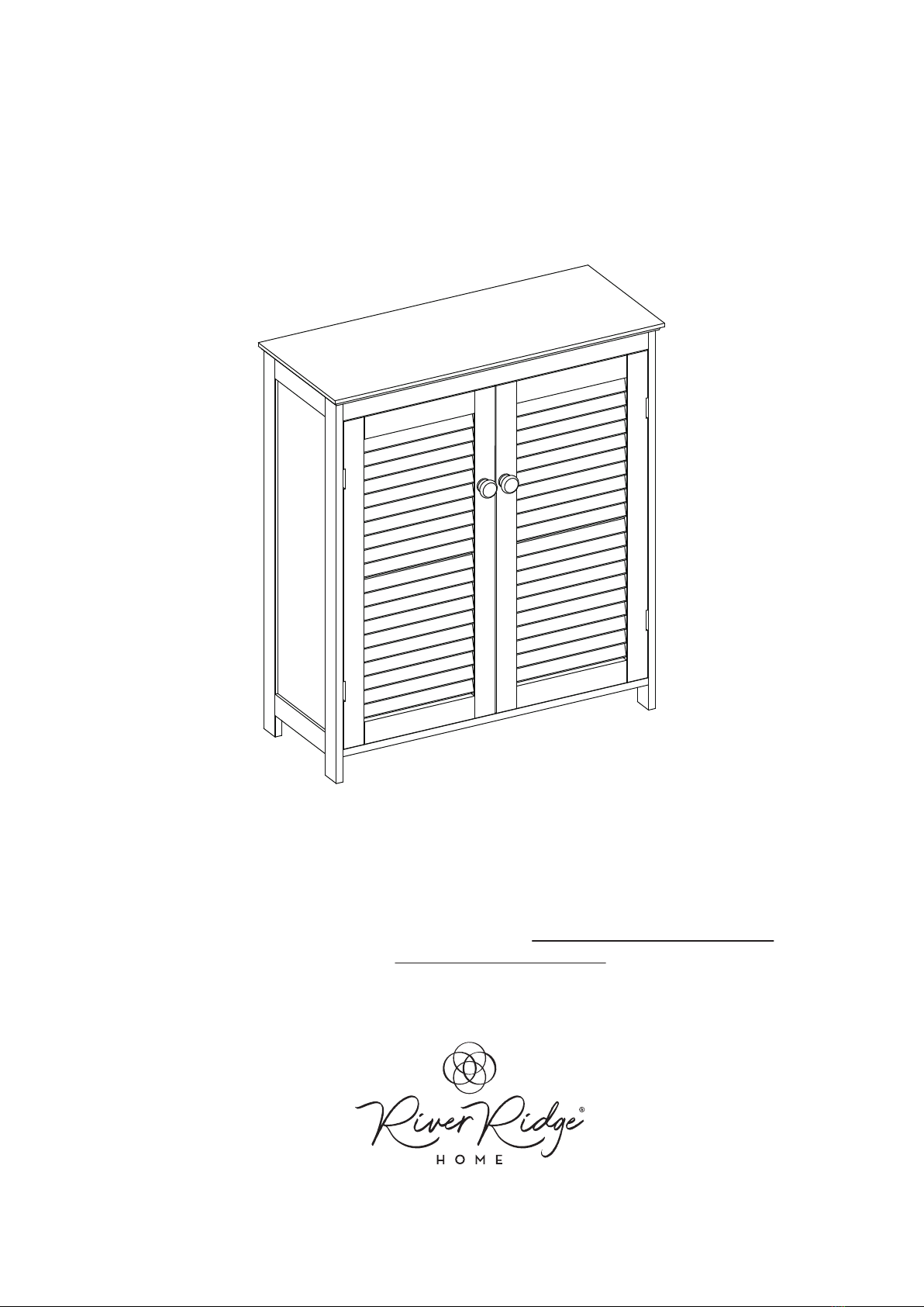
RiverRidge®Ellsworth Two-Door Floor Cabinet
ITEM#: 06-134 White
ADULT ASSEMBLY REQUIRED
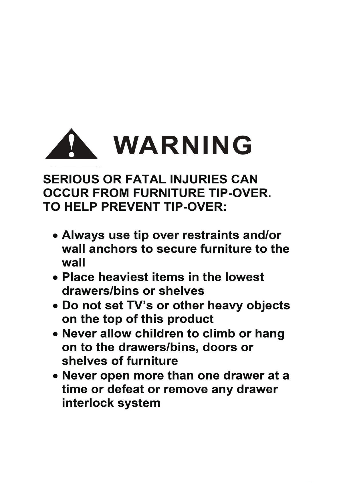
WARNING
SEE FULL WARNING ON PAGE 2
This product requires assembly by an adult because of small parts. Care should be taken
in unpacking and assembling this item to keep small parts away from children. During assembly
children should be kept away from the product due to possible risk of injury.
Young children can be seriously injured or killed if furniture tips over.
Don’t use this item for a TV stand or place heavy objects on top of item.
Always use angle-braces or anchors to secure furniture to the wall.
THIS SHELF UNIT WILL HOLD UP TO 20 POUNDS PER SHELF OR A TOTAL OF 80 POUNDS.
DO NOT LOAD EACH SHELF WITH MORE THAN 20 POUNDS OR 80 POUNDS TOTAL
WEIGHT. IF OVERLOADED WITH MORE THAN 20 POUNDS PER SHELF OR 80 POUNDS
TOTAL WEIGHT, SHELF MAY TIP FROM THE WALL AND CAUSE SERIOUS INJURY OR DEATH.
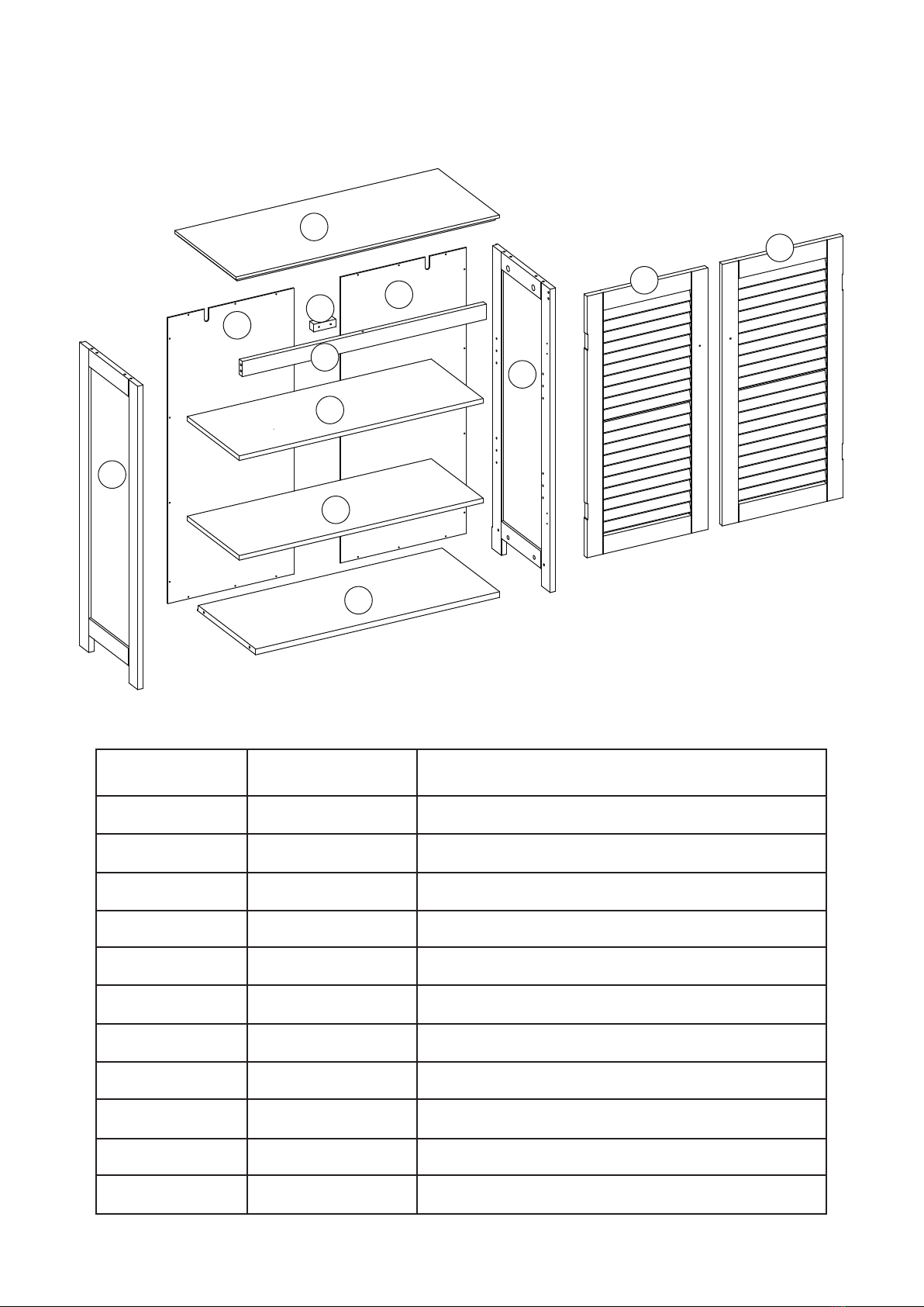
PARTS LIST
2
1
3
4
5
6
7
7
8
910
11
NO QTY DESCRIPTION
1 1PC
2 1PC
3 1PC
4 1PC
5 1PC
6 1PC
7 2PCS
8 1PC
9
10
11
1PC
1PC
1PC
Top Board
Left Side Panel
Right Side Panel
Bottom Board
Cross Bar
Block
Adjustable Shelf
Right Back Panel
Left Door
Left Back Panel
Right Door

PARTS LIST
TOOLS NEEDED FOR ASSEMBLY: FLAT & PHILLIPS SCREWDRIVER (NOT INCLUDED)
THE USE OF A POWER SCREWDRIVER IS NOT RECOMMENDED FOR ASSEMBLY
DO NOT USE ITEM IF ANY PARTS ARE MISSING OR DAMAGED
1-(844)-223-5201 or order parts online at www.riverridgehome.com. Only valid in the United States.
If purchased outside of the United States, please contact retailer where purchased.
NO QTYPARTS DESCRIPTION
A
B
C
D
E
F
G
H
I
J
K
L
M
N
O
P
Q
R
8PCS Cam Bolt
8PCS Cam Lock
12PCS Wood Dowel
1 SET Magnet
18PCS Screw (3x12mm)
20PCS Screw (2.5x10mm)
2PCS Magnet Plate
2PCS
8PCS
Knob
2PCS
4PCS
2PCS
Shelf Holder
2PCS
Plastic Anchor
Adjustable Anchor Bracket
Hinge
2PCS Screw (4x30mm)
Screw (4x10mm)
2PCS Screw (4x30mm)
Screw (4x45mm)1PC
2PCS
1PC
Machine Screw (4x18mm)
Plastic Connection Strip

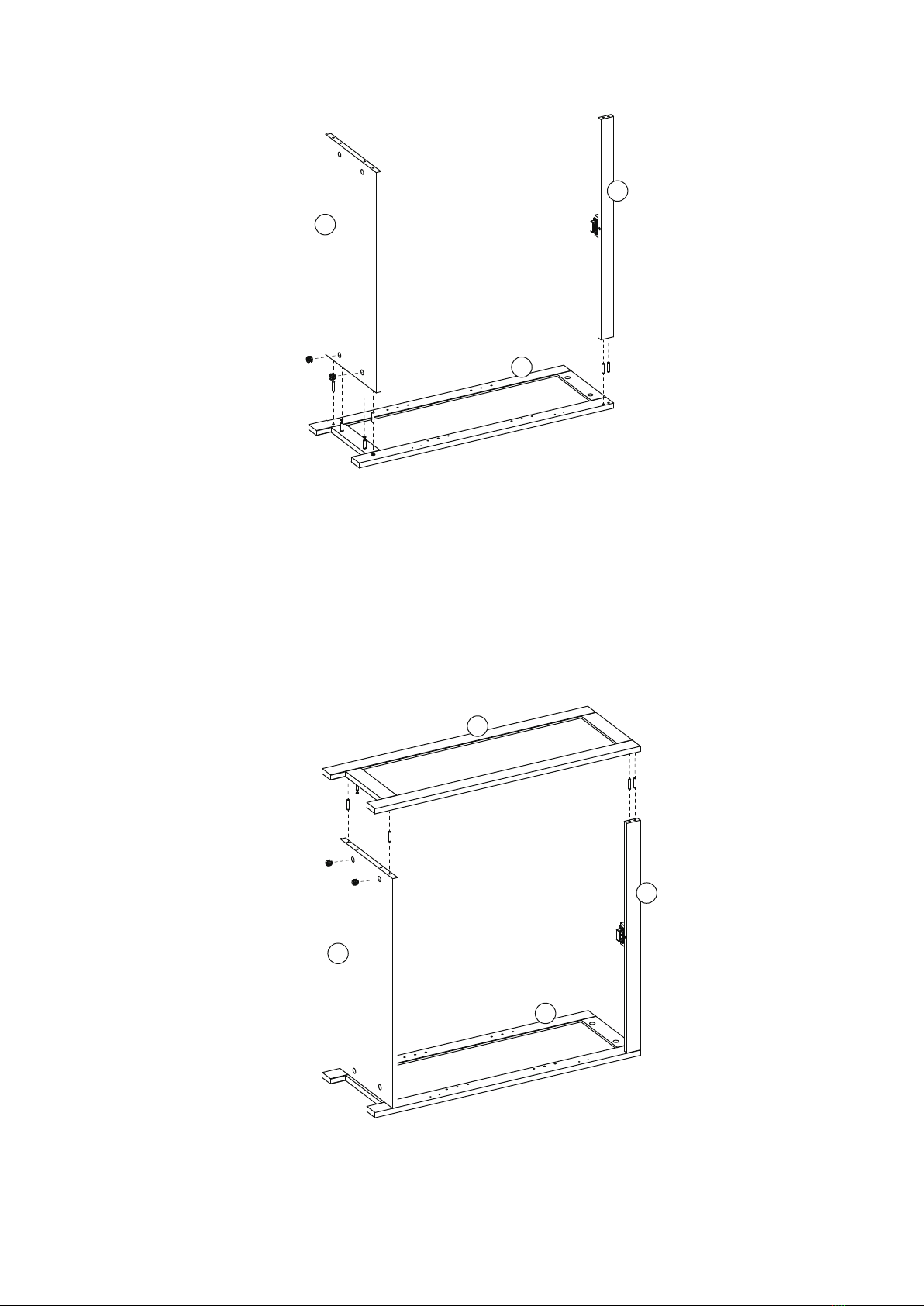
STEP 1
STEP 2
AA
AA
D
5
6
6
N
N
2
3
1. Screw 2 cam bolts (A) into cam bolt holes on left side panel (2).
2. Screw 2 cam bolts (A) into cam bolt holes on right side panel (3).
1. Attach magnet (D) to block (6) by inserting 2 screws through holes on magnet (D), then
tighten to block (6).
2. Attach block (6) to cross bar (5) by inserting 2 screws (N) through holes on block (6), then
tighten to cross bar (5).
STEP 3
STEP 4
4
5
3
2
C
C
C
C
C
C
C
C
B
B
B
B
3
5
4
1. Insert 4 wood dowels (C) into wood dowel holes on right side panel (3).
2. Attach bottom board (4) and cross bar (5) to right side panel (3) by inserting cam bolts (A)
into cam lock holes and wood dowels (C) into wood dowel holes on bottom board (4) and
cross bar (5).
3. Insert 2 cam locks (B) into cam lock holes on bottom board (4), then rotate clockwise to
secure cam bolts in place.
1. Insert 4 wood dowels (C) into wood dowel holes on left side panel (2).
2. Attach left side panel (2) to bottom board (4) and cross bar (5) by inserting cam bolts (A) into
cam lock holes and inserting wood dowels (C) into wood dowel holes on bottom board (4)
and cross bar (5).
3. Insert 2 cam locks (B) into cam lock holes on bottom board (4), then rotate clockwise to
secure cam bolts in place.

STEP 5
STEP 6
A
A
A
A
K
K
M
M
1
C
C
CCBB
B
B
P
4
5
1
23
1. Screw 4 cam bolts (A) into cam bolt holes on top board (1).
2. Attach 2 adjustable anchor brackets (K) to top board (1) by inserting 2 screws (M) through
holes on adjustable anchor brackets (K), then tighten to top board (1).
1. Insert 4 wood dowels (C) into wood dowel holes on top board (1).
2. Attach top board (1) to left side panel (2), right side panel (3) and cross bar (5) by inserting
cam bolts (A) into cam lock holes and inserting wood dowels (C) into wood dowel holes on
left side panel (2) and right side panel (3).
3. Insert 4 cam locks (B) into cam lock holes on left side panel (2) and right side panel (3), then
rotate clockwise to secure cam bolts in place.
4. Insert 1 screw (P) through hole on cross bar (5), then tighten to top board (1).

STEP 7
STEP 8
8
8
9
9
R
R
1
3
4
F
F
F
FF
F
F
F
8
9
2
1
3
4
7
7I
II
I
I
I
I
I
I
1. Add 1 plastic connection strip (R) between left back panel (8) and right back panel (9);
make sure 2 back panels slide into the grooves on plastic connection strip (R).
2. Attach left back panel (8) and right back panel (9) to back of cabinet by inserting 20
screws (F) through holes on left back panel (8) and right back panel (9), then tighten to back
of cabinet.
1. Insert 8 shelf holders (I) into holes on left side panel (2) and right side panel (3); make sure
shelf holders (I) are at same levels.
2. Place adjustable shelves (7) onto shelf holders (I).

STEP 9
STEP 10
10
11
EE
EE
EE
EE
E
E
L
L
L
L
H
H
Q
Q
G
G
3
4
1
2
11
10
E
E
E
E
1. Attach 2 hinges (L) to left door (10) by inserting 4 screws (E) through holes on 2 hinges (L),
then tighten to left door (10).
2. Attach magnet plate (G) to left door (10) by inserting 1 screw (E) through hole on magnet
plate (G), then tighten to left door (10).
3. Attach knob (H) to left door (10) by inserting 1 machine screw (Q) through hole on left
door (10), then tighten to knob (H).
4. Repeat above steps to assemble 2 hinges (L), magnet plate (G) and knob (H) to right door (11).
1. Attach left door (10) to left side panel (2) by inserting 4 screws (E) through holes on hinges (L),
then tighten to left side panel (2).
2. Attach right door (11) to right side panel (3) by inserting 4 screws (E) through holes on
hinges (L) then tighten to right side panel (3).
ATTENTION ADULTS: Cabinet should be checked periodically for damage or
loose screws/parts. Take appropriate action necessary to correct hazards such as
tightening of screws and taking any damaged parts away from children.
WARNING Please make sure youritem is
secured to the wall, per assembly instructions.
CARE INSTRUCTIONS:
Wipe clean with a water dampened cloth. Wipe dry with clean cloth.
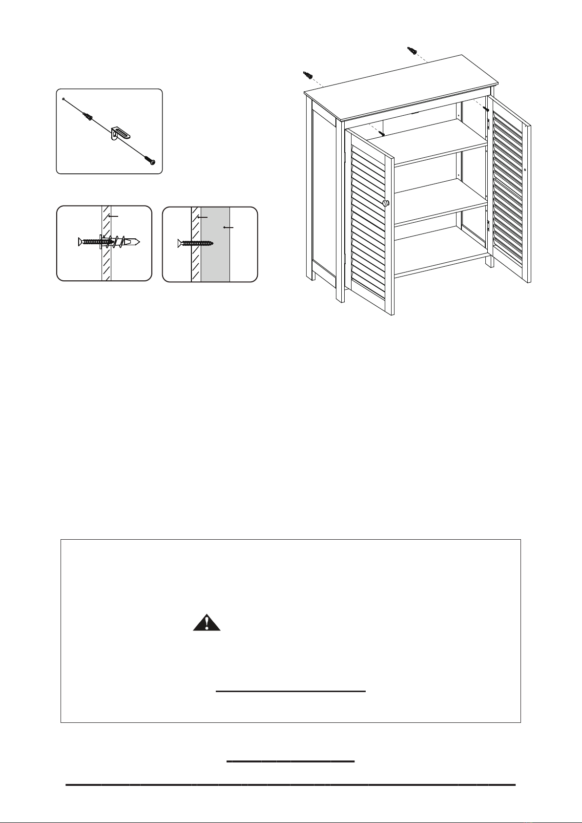
STEP 11
DRYWALL
LWAL ANCHOR
WITH SCREW
SCREW
ONLY
DRYWALL
OPTION #2
OPTION #1
WOOD
STUD
O
O O
J
J
K
Option #1: Securing to Drywall
1. Position cabinet against wall in desired location. Using a pencil, make 2 small marks on wall
through holes on brackets (K). Move cabinet away from wall and screw 2 plastic anchors (J)
into wall on pencil marks.
2. Place cabinet against wall, insert 2 screws (O) through holes on brackets (K), then tighten to
plastic anchors (J).
Option #2: Securing to Drywall and Wood Stud
1. Position spacesaver against wall in desired location. Insert 2 screws (O) through holes on
brackets (K), then tighten through drywall and into wood stud.
*Tip: Adjustable anchor brackets (K) can be adjusted to correct distance from wall to cabinet as
needed. Once adjusted, be sure to re-tighten brackets inside cabinet for stability.
IMPORTANT:
Keep assembly instructions for future reference.
STEP 11
DRYWALL
LWAL ANCHOR
WITH SCREW
SCREW
ONLY
DRYWALL
OPTION #2
OPTION #1
WOOD
STUD
O
O O
J
J
O
O
J
J
K
Thank you for purchasing this RiverRidge® Home item. We hope you
enjoy it and consider purchasing other RiverRidge® items.
RiverRidge® is a registered trademark of Sourcing Solutions, Inc., Hudson, WI 54016
Enjoy your new RiverRidge®Cabinet!
1-(844)-223-5201 or order parts online at www.riverridgehome.com. Only valid in the United States.
If purchased outside of the United States, please contact retailer where purchased.
Table of contents
Popular Indoor Furnishing manuals by other brands

Home Decorators Collection
Home Decorators Collection WBPV4821D Use and care guide

JR Knight
JR Knight ZKOC-01 user manual

Sunjoy
Sunjoy Renaissance L-DN1065SAL quick start guide

Kis
Kis LOGICO 9634000 Assembly instruction

Bestar
Bestar 60510-2163 Assembly instructions

Manutti
Manutti Zendo Sense instruction manual

FMD Furniture
FMD Furniture 939-001 Assembly instructions

Arthauss Furniture
Arthauss Furniture POLA Assembly instructions

Seville Classics
Seville Classics NSF WEB452 Assembly instructions

diotti
diotti Barcode Sideboard Assembly sheet

Balt
Balt 34419R 34450 Assembly instructions

OVE
OVE DARCY 60 installation manual


