SOURIAU MSH Series User manual

Connectors for Navy Applications
and Heavy Duty Industries
MSH/MPH SERIES


3
MSH/MPH series
Contents
• Introduction .................................................................................................................................................................................................................... 4
• Applications ................................................................................................................................................................................................................... 5
• Description ..................................................................................................................................................................................................................... 7
• Schematic ....................................................................................................................................................................................................................... 8
• Characteristics ............................................................................................................................................................................................................ 10
• Contacts ......................................................................................................................................................................................................................... 11
• Polarization keys ......................................................................................................................................................................................................... 15
• Cable codes ................................................................................................................................................................................................................. 15
• References ................................................................................................................................................................................................................... 16
• Contact layouts ........................................................................................................................................................................................................... 17
• Dimensions .................................................................................................................................................................................................................. 20
• Spare parts .................................................................................................................................................................................................................. 27
• Tools ............................................................................................................................................................................................................................... 28
• Wiring instructions .................................................................................................................................................................................................... 32
• Recommended connectors .................................................................................................................................................................................. 34

4
MSH/MPH series
Introduction
MSH and MPH series cylindrical connectors comply with environmental tests of French standard NFC 93422 and satisfy
the requirements of marine specification 538c AGB/T.They are listed in GAM T1 and MAT 6840005.
• Two series are available:
These series are available with 8 shell sizes and large variety of layouts including signal, power and RF conntacts.
• New Cadmium Free plating available for MSH series:
- MSH Aluminium shells plated with Tin over nickel to be compliant with ROHS requirements.
Series Shell Remarks
MSH Treated aluminium alloy HALOGEN free
MPH Bronze HALOGEN free
5
MSH/MPH series
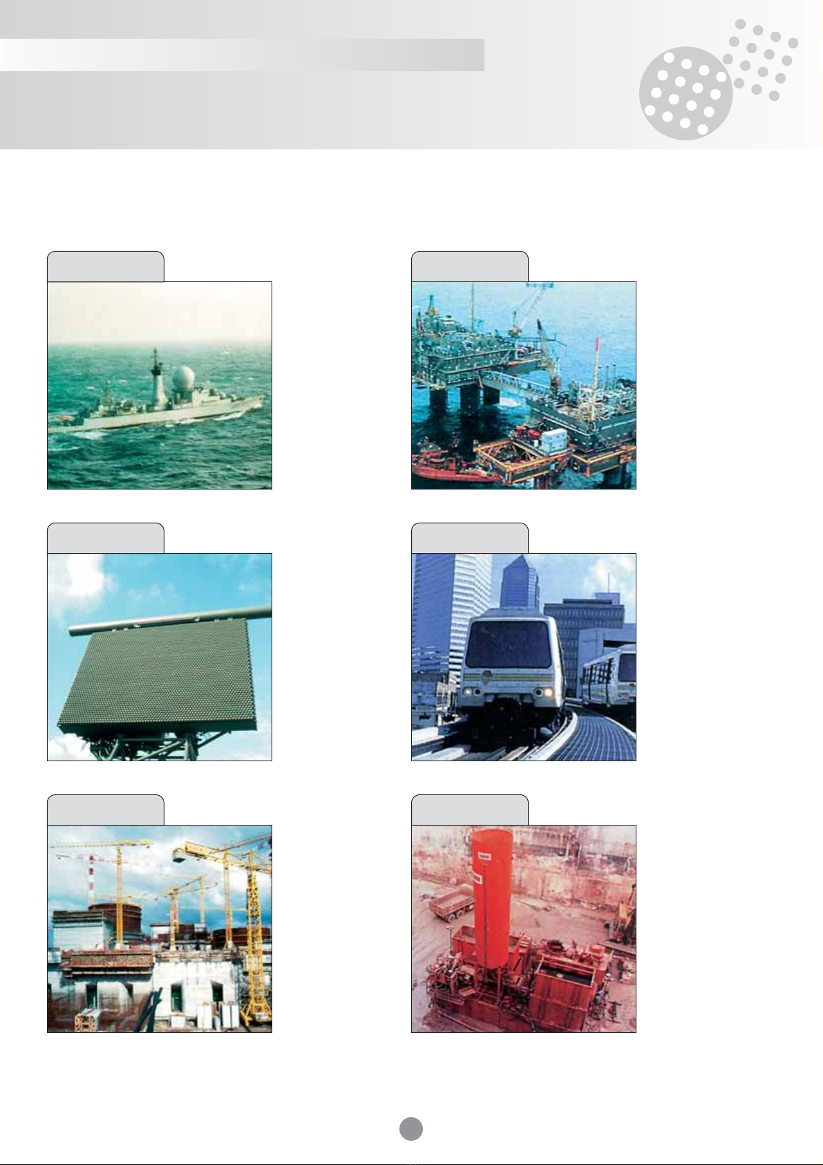
Applications
The highly robust design of MSH/MPH series makes them particularly suited for naval and heavy-duty industry applications.
• upper decks
• radars
• monitoring and power
supply racks
• platform
• armament systems
• platform
• gas or petrol
exploitation
• heavy plant
• power units
• inter-carriage
connections
• power supply racks
• trackside beacons
• power supply units
• cranes
• heavy plant
• tunneling machines
• concreting
• power supply units
• power supply units
• shelters
• communications
networks
• artillery
• radars
• steel industry
• shipbuilding
• petrochemicals
• power industry
• mining
Offshore industry
Navy
Ground-based
armament Rail transport
Heavy duty industry Construction industry

6
MSH/MPH series
Features Benefits
Mechanical
• Square threaded screw coupling • High vibration and shock withstanding.
(plug on receptacle). • Suitable for Harsh Environment application
• Conical coupling interface. (railways, mining, public works…).
• Special cone-design on backshell • Extreme resistance to pull out
for cable braid retention. or transverse forces on cable (80 kg).
• 5 key mechanical polarisation. • Reliable and safe mating.
• Scoop proof shells.
Environmental
• Oring sealing between plug and receptacle. • High performance sealing:
- permanent IP68,
• Packing seal on backshell to cable interface. - Permanent water immersion
up to 2 meters,
• Cable boot on backshell interface. - Compliance with main Marine
and Heavy Industries cable.
• Tin plated Aluminium • High corrosion resistance
or Marine bronze shells (salt spray, sea water, sand, dust,
hydrocarbons fluids…).
• RoHS compliant.
Electrical
• Dismountable crimp contacts. • Easy wiring.
• Growding ring on plug side. • EMI/RFI/protection.
Features and benefits
The very ruggedized design of MSH/MPH series brings the following benefits :

7
MSH/MPH series
Description
• Eight shell sizes, numbered 16-17-18-20-22-
24-26-28.
•Assembly and removal of push-on contacts
into the insulator via the rear of the shell.
• Assembly and removal of screw contacts via
the rear of the insulator.
• Leaktight sealing caps for plugs and
receptacles.
• Watertightness of shells and accessories via
O-ring seals (15 and 19).
• Seal with the cable via cable gland-type
elastomer seal (26).
• Cable held at 3 levels: cable clamp
(27 and 28), cable gland (25 and 26),
braid grip (21, 22, 23 and 24).
• Cable boot (29) for limiting the radius
of curvature of the cable on leaving the
connector.
1. E44-type receptacle body
2. Insulator collar
3. Rear insulator
4. Intermediate insulator
5. Contact retaining clips
6. Flat gasket for square flange receptacle,
and O-ring seal for nut fixing
7. End stop insulator
8. Male contact (ref.: M)
9. Male front insulator
10. Plugshell
11. Contact clips
12. Locking device
13. Female front insulator
14. Female contact (ref.: K)
15. Front plug O-ring seal
16. Grounding ring for MSH and MPH series
17. Rear friction washer
18. Connector coupling ring
19. Rear plug O-ring seal
20. Leaktight elbow backshell
21. Braid grip locking screw
22. Braid grip cone
23. Braid grip bush
24. Braid grip stop
25. Support washer
26. Gasket
27. Cable clamp with antirotation pins
28. Locking screw
29. Cable boot

8
MSH/MPH series
General configuration
For single or multi-contact signal, coaxial and power layouts with pins of less than 8 mm diameter.
To order accessory only : add Z suffix to the P/N. See glossary page 9.

9
MSH/MPH series
Single contact connectors configuration
Glossary
For single contact power layouts with pins between 10 mm and 25 mm in diameter.
To order accessory only : add Z suffix to the P/N.
Standard shell
Long shell
power single
contact
Series MSH MPH
Shell type
Plug FZ F1 FZ F1
Receptacle, front axial nut E2 E2
Receptacle, 4-screw fixing E44 E44
Receptacle, no accessory options, 4-screw fixing E43 E43
Receptacle, no accessory options, rear axial nut E0 E0
Bulkhead TRE -
Plug sealing cap BF BF
Plug sealing cap with eyelet lanyard BFC BFC
Receptacle sealing cap BE BE
Receptacle sealing cap with ring lanyard BEB(A) BEB(A)
Receptacle sealing cap with eyelet lanyard BEC BEC
(A) For E2-type receptacle.
Plug F5 F5
Receptacle, front axial nut E32 E32
Receptacle, 4-screw fixing (6) E33 E33
Plug sealing cap BF5 BF5
Plug sealing cap with lanyard BF5C BF5C
Accessories(1)
Leaktight straight backshell RD(3)
Leaktight elbow backshell(2) RL(3)
Non-leaktight cable clamp(2) SC(3)
Non-leaktight wire grip(2) SF(3)
Thread mask backshell RZT

10
MSH/MPH series
Mechanical
• Shells
- Series MSH: aluminum alloy.
- Protection:
- Tin plated on nickel underlayer;
Nickel: 10 µm
Tin: 35 µm.
- or cadmium plated bichromated-treated
on nickel under layer (standard)
- Series MPH: marine bronze.
• Seal and cable boot
- Elastomer.
• Flexible insulation, front and rear
- Silicone elastomer.
• Rigid insulation
- Polyoxy phenylene reinforced PPOm.
• Contacts
- Copper or copper alloy.
- Protection : gold plating on nickel
for contacts mx8.
- Silver on nickel for contacts > x8.
• Mechanical endurance
- 200 to 500 locking/unlocking cycles
(depending on size).
• Charge in cantilever: m800 N
• Cable pulling: m800 N
• Free fall: 2,5 m
- Trampling: m80 kg.
Electrical
• Withstand voltage:
At normal pressure
1500 V between contacts size 20,
2500 V for the other contacts.
• Insulation resistance:
- Cabled plug : M104Mh
- Cabled receptacle : M104Mh
- Coupled connectors : M5.103Mh
• Metallization Resistance:
On coupled connectors between
the receptacle plate and rear of plugshell : ≤
m 2.5 mh
Environmental
• Operating temperature:
-55°C to +125°C.
• Immersion resistance:
- 0.2 bars, serie MSH - 2 bars, serie MPH.
• Impact:
100 g - 11 ms - 2 impacts/direction/ axes.
• Vibrations:
- 0.35 mm during 1 h - sweep from 5 to 55 Hz
on the 3 axis.
• Salt spray:
- Series MSH: 6 x 48 h cycles.
- Series MPH: 20 x 48 h cycles.
• Humid heat: 56 days at 40°C.
• Resistance to liquids:
- Kerosene, JP4, 35A, 3515 - oronire
and skydrol 508/A.
• NBC Protection: Resistant to
decontaminating agents.
Characteristics

11
MSH/MPH series
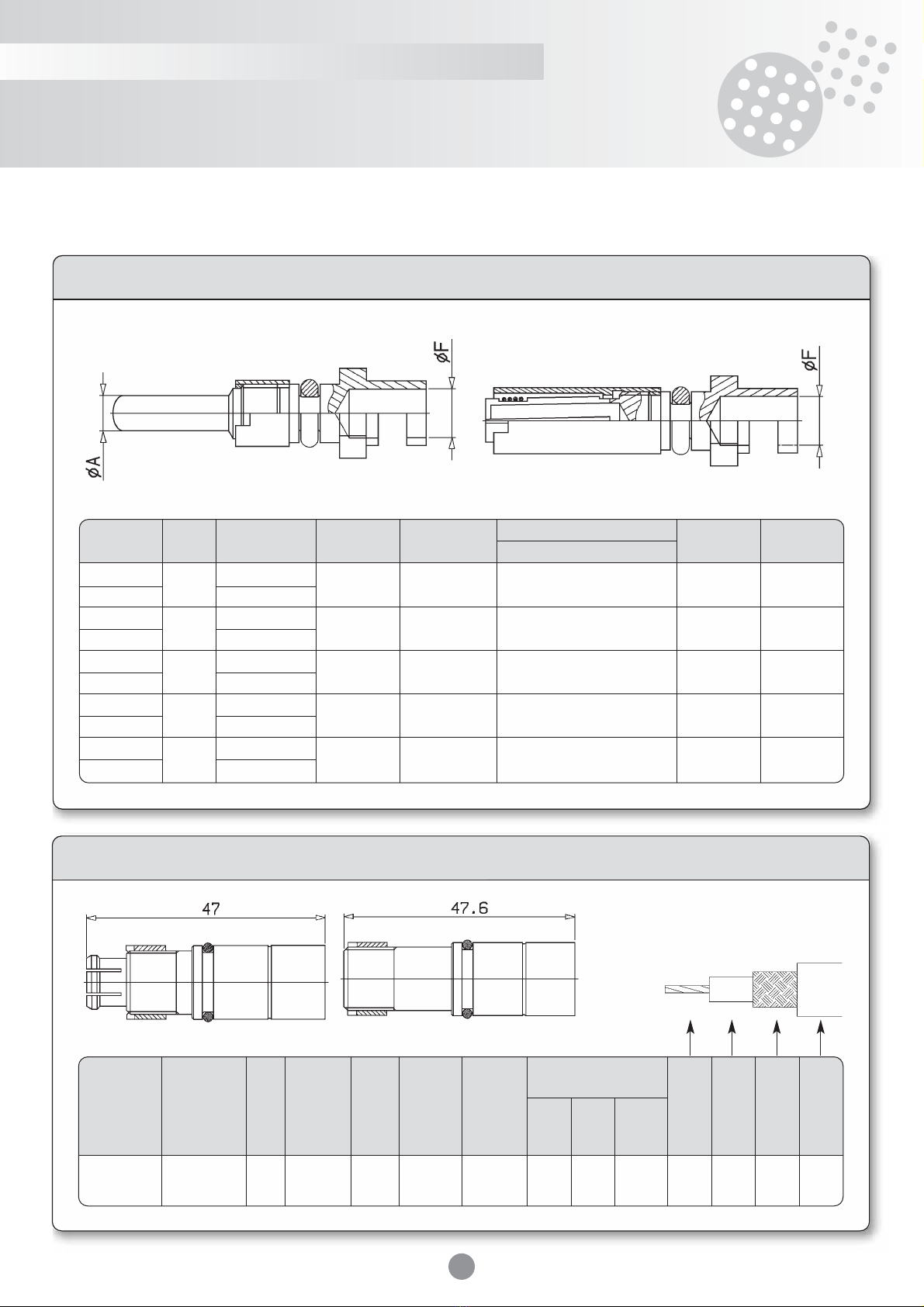
Power crimp contacts
Crimp contacts
Type Size Part number Max. Contact Permissible cables Ø A Ø F
current A resistance m
h
Section mm2AWG gage contact barrel
Male 20 M-20-MS 7
m
2 0,38 to 0,93 22 to 18 1,6 1,35
Female K-20-MS
Male 16 M-16-MS 13
m
1,5 0,93 to 1,91 18 to 14 1,6 2,00
Female K-16-MS
Male 12 M-12-MS 20
m
1,2 1,91 t o3,18 14 to 12 2,4 2,55
Female K-12-MS
Reducing 20 MKMS-20-28 0,1 to 0,15 28 to 26 0,65
sleeves MKMS-20-24 0,21 to 0,38 24 to 22 0,95
16 MKMS-16-26 0,15 to 0,6 26 to 20 1,2
MKMS-12-22 0,1 to 0,38 28 to 22 0,9
12 MKMS-12-18 0,38 to 0,93 22 to 18 1,40
MKMS-12-16 0,6 to 1,34 20 to 16 1,70
Contacts
Max. Contact Permissible cables Ø A Ø F
Type Size Part number current A resistance m
h
Section mm2contact barrel
Flexible Extra flexible
Male 8M-8-MS 45
m
1 5,15 to 10 3,18 to 6 3,6 4,4
Female K-8-MS
Male 6M-6-MS 10 6 5
Female K-6-MS 75
m
0,8 4,6
Male 6E M-6E-MS 16 10 5,5
Female K-6E-MS
Male 25C M-25C-MS 25 16 7,7
Female K-25C-MS 120
m
0,5 6,7
Male 25CE M-25CE-MS 35 25 9
Female K-25CE-MS
Male 50MC M-MS-50MC 170
m
0,3 50 40 8 10,3
Female K-MS-50MC
Réducing 8 MK-MS-8-12 3,18 to 5,15 3,4
sleeve
Pin Socket Reducing sleeve
Pin Socket Reducing sleeve

12
MSH/MPH series
Power single crimp contact
Max. Contact Permissible cables Ø A Ø F L
Type Size Part number current A resistance m
h
Section mm2contact barrel Max
Flexible Extra flexible
Male 50C M-50C-MS 50 45 10,8 65
Female K-50C-MS 235 66
Male 50CE M-50CE-MS 60 50 11,8 65
Female K-50CE-MS
m
0,08 10 66
Male 70C M-70C-MS 70 60 12,5 65
Female K-70C-MS 291 66
Male 70CE M-70CE-MS 95 70 14,5 65
Female K-70CE-MS 66
Male 95C M-95C-MS 95 70 14,5 68
Female K-95C-MS 352
m
0,05 14 66
Male 95CE M-95CE-MS 120 95 17 68
Female K-95CE-MS 69
Male 185C M-185C-MS 185 150 20,5 70
Female K-185C-MS 535
m
0,03 18 71
Male 185CE M-185CE-MS 240 185 23 70
Female K-185CE-MS 71
Male 300C M-300C-MS 300 240 26 80
Female K-300C-MS 723
m
0,02 25 81
Male 300CE M-300CE-MS 350 300 28 80
Female K-300CE-MS 81
Contacts
Pin Socket
13
MSH/MPH series
Power solder contacts
Watertight coaxial contacts
Contacts
Pin Socket
Male Female
Type Size Part number Max. Contact Permissible cables Ø A Ø F
current A resistance m
h
Section mm2contact barrel
Male 6MC M-MS-6MC 27
m
1 5,94 Max. 2,8 3,4
Female K-MS-6MC
Male 10MC M-MS-10MC 45
m
1 10,5 Max. 3,6 5
Female K-MS-10MC
Male 16MC M-MS-16MC 65
m
0,8 15,82 Max. 4,6 6
Female K-MS-16MC
Male 25MC M-MS-25MC 90
m
0,8 24,62 Max. 5,7 7,8
Female K-MS-25MC
Male 35MC M-MS-35MC 120
m
0,5 34,67 Max. 6,7 9
Female K-MS-35MC
Withstand Part number of
Male Female voltage, Max Insulation Contact permissible cables
x
A
x
B
x
C
x
D
part number part number Sea level Current resistance resistance MIL NFC Marine max. max. max. max.
Vrms 50 Hz AM
h
M
h
C17 93.550 599a
TQL/TR
CM-50A-MSH CK-50A-MSH 50 2500 12 > 5000
m
3 / / 50MSB 1,9 7,6 8,6 11
CM-75A-MSH CK-75A-MSH 75 2700 5
m
4 / / 75MSB 1
Impedance
h

14
MSH/MPH series
Standard - watertight - coaxial contacts
Contacts
Withstand Part number of
Male Female voltage, Max Insulation Contact permissible cables
x
A
x
B
x
C
x
D
part number part number Sea level Current resistance resistance MIL NFC Marine max. max. max. max.
Vrms 50 Hz AM
h
M
h
C17 93.550 599a
TQL/TR
KX2(1)
CM-501-MS CK-501-MS RG58 KX15 50PPN 3,1 4,1 6,5
RG122
RG174 KX3 50RPN
CM-502-MS CK-502-MS 50 1200 4 > 5000
m
5 RG316 KX22 50RT 1,1 1,6 2,2 2,7
CM-507-MS CK-507-MS RG178 KX21 1,6 1,7 2,1
RG223
CM-508-MS CK-508-MS RG142 KX23 3,1 4,3 6,5
50PSB
RG59 KX6 75PPN
CM-751-MS CK-751-MS RG140 KX25 75PD 3,8 4,6 6,5
75 1500 2,5 > 5000
m
8 RG302 0,7
CM-752-MS CK-752-MS RG179 1,7 2,3 2,7
CM-758-MS CK-758-MS 75PSB 3,8 4,8 6,5
OBT-CM-MS OBT-CK-MS Sealing plug
Impedance
h
Miniature - non-watertight - coaxial contacts
Male Female
Withstand Part number of
Male Female voltage, Max Insulation Contact permissible cables
x
A
x
B
x
C
x
D
part number part number Sea level Current resistance resistance MIL NFC Marine max. max. max. max.
Vrms 50 Hz AM
h
M
h
C17 93.550 599a
TQL/TR
CM-511-MS(1) CK-511-MS(1) RG178 KX21 0,3 0,9 1,7 2
RG174 KX3 50RPN 0,5 1,6 2,2 2,8
CM-512-MS(1) CK-512-MS(1) RG316 KX22 50RT
50 600 2 > 5000
m
12 RG178 KX21
CM-521-MS(2) CK-521-MS(2) RG174 KX3 50RPN 0,5 1,6 2,2 2,8
RG316 KX22 50RT
Impedance
h
Male Female
(1) Withdrawn from spécification NFC93550; replaced by KX15.
(1) “RADIALL” crimp contacts. (2) “RAYCHEM” thermo-soldering contacts.
15
MSH/MPH series
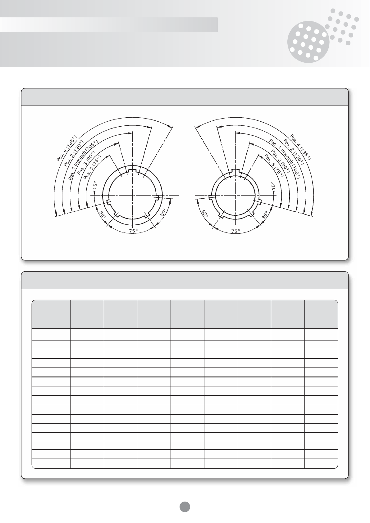
Polarization keys
Cable code
16 17 18 20 22 24 26 28
A0 22,2 to 23,1 29,2 to 30,2 34 to 35,4
A14,5 to 16 17,5 to 19 20,5 to 22,2 25,5 to 27 27,5 to 29,2 30,5 to 32 32,5 to 34 40,5 to 42
A1 13 to 14,5 17 to 17,5 19 to 20,5 24 to 25,5 26 to 27,5 29 to 30,5 31 to 32,5 39 to 40,5
B12 to 13 15 to 16 17,5 to 19 22,5 to 24 24,5 to 26 27,5 to 29 29,5 to 31 37,5 to 39
B1 11 to 12 14 to 15 16 to 17,5 21 to 22,5 23 to 24,5 26 to 27,5 28 to 29,5 36 to 37,5
C10 to 11 13 to 14 14,5 to 16 19,5 to 21 21,5 to 23 24,5 to 26 26,5 to 28 34,5 to 36
C1 9 to 10 12 to 13 13 to 14,5 18 to 19,5 20 to 21,5 23 to 24,5 25 to 26,5 33 to 34,5
D8 to 9 11 to 12 12 to 13 16,5 to 18 18,5 to 20 21,5 to 23 23,5 to 25 31,5 to 33
D1 7 to 8 10 to 11 11 to 12 15 to 16,5 17 to 18,5 20 to 21,5 22 to 23,5 30 to 31,5
E6 to 7 9 to 10 10 to 11 13,5 to 15 15,5 to 17 18,5 to 20 20,5 to 22 28,5 to 30
E1 5 to 6 8 to 9 9 to 10 12 to 13,5 14 to 15,5 17 to 18,5 19 to 20,5 27 to 28,5
F7 to 8 8 to 9 10,5 to 12 12,5 to 14 15,5 to 17 17,5 to 19 25,5 to 27
F1 6 to 7 7 to 8 9 to 10,5 11 to 12,5 14 to 15,5 16 to 17,5 24 to 25,5
G22,5 to 24
G1 21 to 22,5
Viewed from receptacle mating Viewed from plug mating
Shell size
Cable code

16
MSH/MPH series
37-20 RST A1 T P3 A
MSH
MPH
22MRLE2
References
Standard shell
Long shell
power single
contact
Series MSH MPH
Shell type
Plug FZ F1 FZ F1
Receptacle, front axial nut E2 E2
Receptacle, 4-screw fixing E44 E44
Receptacle, no accessory
options, 4-screw fixing E43 E43
Receptacle, no accessory
options, rear axial nut E0 E0
Bulkhead TRE -
Plug sealing cap BF BF
Plug sealing cap with
eyelet lanyard BFC BFC
Receptacle sealing cap BE BE
Receptacle sealing cap
with ring lanyard BEB(A) BEB(A)
Receptacle sealing cap
with eyelet lanyard BEC BEC
(A) For E2-type receptacle.
Plug F5 F5
Receptacle, front axial nut E32 E32
Receptacle, 4-screw fixing (6) E33 E33 (6)
Plug sealing cap BF5 BF5
Plug sealing cap with lanyard BF5C BF5C
Accessories(1)
Leaktight straight backshell RD(3)
Leaktight elbow backshell(2) RL(3)
Non-leaktight cable clamp(2) SC(3)
Non-leaktight wire grip(2) SF(3)
Thread mask backshell RZT
Insulation type(6)
Male M
Female K
Shell size
16-17-18-20-22-24-26-28 XX
Connector series
MSH connectors
MPH connectors Halogen free XXX
Contact layout(6)
Number/size of contact XX-XX
see § layout
Braid grip(1) (for RD and RL)
With braid grip RST
Without braid grip Y
With braid grip power
single contact PST
Cable code(1) (for RD, RL and SC)
A to E1 XX
see § cable codes
Cable boot(1)(for RD and RL)
With cable boot T
Without cable boot (no mention) -
Polarization key(6)
Normal P1
Other position P2-P3-P4-P5 PX
see § polarization key
Surface treatment
Tin plated(7) A
Cadmium-plated bichromate-treated -
Olive drab 014
(1) Leave a blank if the connector has no accessories - (2) Cannot be fitted to long single-contact power shell - (3) Add Z to the part number for accessory orders only -
(4) Do not use with contacts xA > 3,6 - (5) Leave a blank for accessories only or sealing caps - (6) Consult us for availability.
(7) New plating in compliance with ROHS legislation.
]

17
MSH/MPH series
17
Contact layouts (standard shell)
1
1#16 MC
3
3#16
3
3#20
7
7#20
16
3
3#6
3#6E
3
3#8
3#6 MC
3#10 MC
3
3#16 MC
27
27#20
20
3
3#12
7
7#16
12
12#20
17
Viewed from male connectors mating (The main polarization key is shown in the “normal” position).
1
1-C50A
1-C75A
3
3-C501(1)
3-C502
3-C507
3-C508 (50 h)
3-C751
3-C752
3-C758 (75 h)
3
3#6 MC
3#8
3#10 MC
12
12-C50(2)
Without contacts
12- C511
12 C512
12 C5
12
12#16
19
19#20
18
Legend
Grounding contacts
Note : Do not use insulators with contacts from Ø A > 3,6 in plugs fitted with an elbow backshell RL (z)
(1) See § Standard coaxial contacts - (2) See § Miniature coaxial contacts
Standard AGB/T 538 Non standard

18
MSH/MPH series
Contact layouts (standard shell)
Viewed from male connectors mating (The main polarization key is shown in the “normal” position).
Grounding contacts
Note : Do not use insulators with contacts from Ø A > 3,6 in plugs fitted with an elbow backshell RL (z)
(1) See § Standard coaxial contacts - (2) See § Miniature coaxial contacts
3
3#8
3#6 MC
3#10 MC
3
3#16 MC
3#6
3#6E
3
3#25 MC
4
4#10 MC
4#8
48
48#20
24
3
3#35 MC
3#25C
3#25CE
12
12-C501(1)
12-C502
12-C507
12-C508 (50
h
)
12- C751
12- C752
12-C758 (75
h
)
48
48-C50(2)
without contacts
48-C511
48-C512
61
61#20
26
2
2#25 MC
5
5#10 MC
5#8
7
7-C501(1)
7-C502
7-C507
7-C508 (50
h
)
7-C751
7-C752
7-C 758 (75
h
)
19
19#16
29
29-C50(2)
without contacts
29-C511
29-C512
37
37#20
22
Standard AGB/T 538 Non standard

19
MSH/MPH series
3
3#50 MC
85
85#20
28
Contact layouts (standard shell)
Viewed from male connectors mating (The main polarization key is shown in the “normal” position).
Grounding contacts
Note : Do not use insulators with contacts from Ø A > 3,6 in plugs fitted with an elbow backshell RL (z).
Note : Do not use elbow backshell RL(z) or cable-clamp SC (z) or wire-grip SF(z) with these layouts.
Power single contact layouts (long shell)
1
1#50C
1#50CE
1
1#70C
1#70CE
20
1
1#95C
1#95CE
22
1
1#185C
1#185CE
26
1
1#300C
1#300CE
28
Standard AGB/T 538 Non standard
20
MSH/MPH series
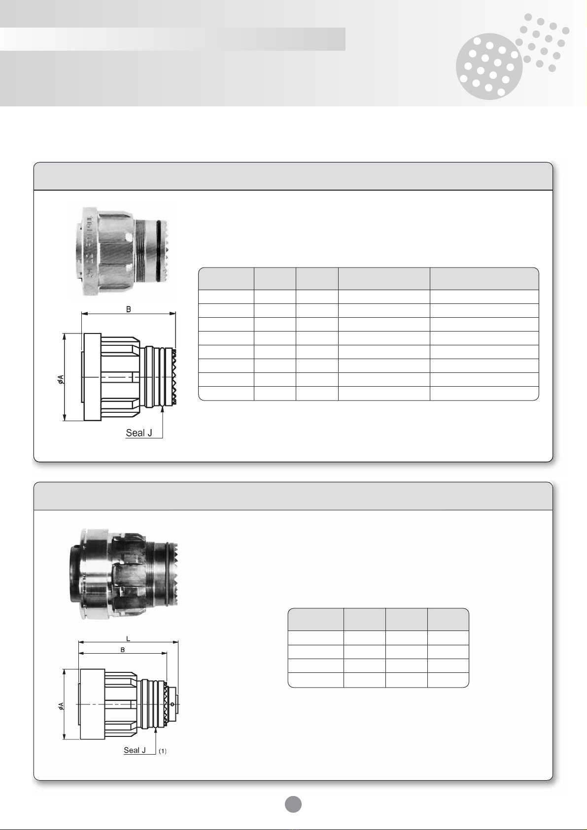
Standard plugs: FZ or F1
Dimensions
Shell size Ø A B “J” seal Internal seal (coupling)
16 35 53
x
1,78 x 18,77
x
1,78 x 17,17
17 39 53
x
1,78 x 21,95
x
1,78 x 20,35
18 43 53
x
1,78 x 26,70
x
1,78 x 25,12
20 48 53
x
1,78 x 29,87
x
1,78 x 28,30
22 52 53
x
1,78 x 33,05
x
1,78 x 31,47
24 56 53
x
1,78 x 34,65
x
1,78 x 34,65
26 59 53
x
1,80 x 37,40
x
1,80 x 37,40
28 74 53,5
x
1,78 x 50,52
x
1,78 x 50,52
Power single contact plug: F5
Size Ø A B L maxi
20 48 61 70
22 52 61 72
26 59 61 74
28 74 61,5 84
(1) See standard (plug)
This manual suits for next models
1
Table of contents
Other SOURIAU Cables And Connectors manuals


