South Bay International SBKD3 User manual
SBKD3
PLEASE READ AND KEEP FOR FUTURE REFERENCE.
THIS MANUAL CONTAINS IMPORTANT SAFETY INFORMATION.
SERIAL NUMBER:
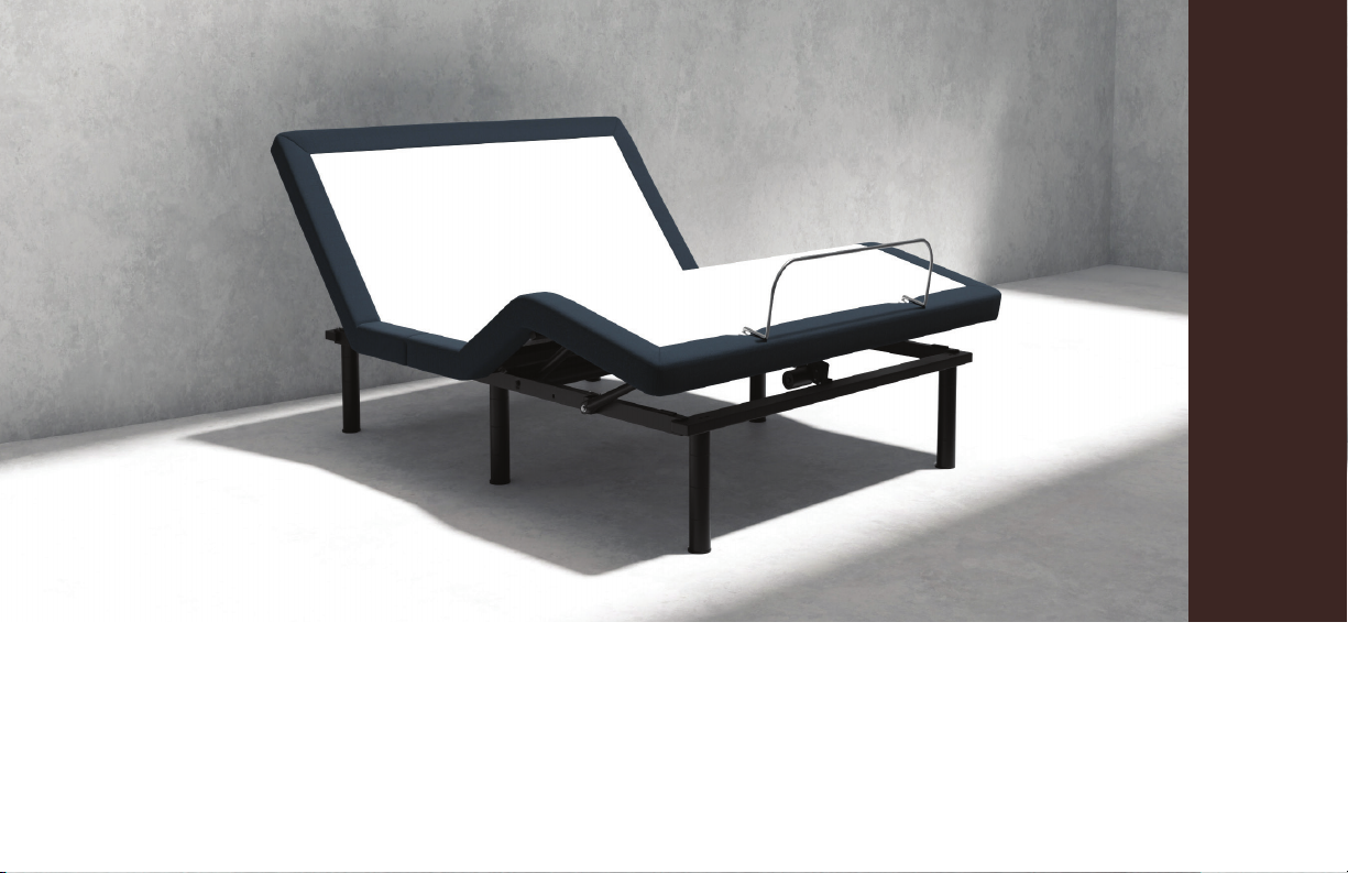
ADJUSTABLE BASE USER MANUAL

CUSTOMER SERVICE 1-877-622-6550 FROM 7:30AM TO 5:00PM PST MONDAY-FRIDAYCUSTOMER SERVICE 1-877-622-6550 FROM 7:30AM TO 5:00PM PST MONDAY-FRIDAY
PAGE 2PAGE 3
TABLE OF CONTENTS
TABLE OF CONTENTS
.........................................................................................3-4
..........................................................................................................5
..........................................................................................................6-8
..............................................................................................9
...................................................................................10
..................................................................11
...............................................................................................12
...............................................................................................................13
.......................................................................................14-15
..................................................................................................16
..............................................................................................................................17
SAFETY INFORMATION
INTRODUCTION
SETUP GUIDE
CONNECTING STRAPS
SYNCHRONIZATION CABLE
HOOK AND LOOP SECURING STRAPS
CHILD SAFETY LOCK
WARRANTY
TROUBLESHOOTING
REFERENCE GUIDE
FAQ
SAFETY
PLEASE READ ALL SAFETY INFORMATION AND INSTRUCTIONS
CAREFULLY BEFORE ASSEMBLY AND USE. VIOLATING ANY SAFETY
INFORMATION WILL VOID THE WARRANTY AND MAY RESULT IN
INJURY OR DAMAGE.
SAFETY INFORMATION
Only use the adjustable base for its intended use as described in this manual. Follow
the guidelines below:
* Avoid fingers in pinch-points.
* Two adults are strongly recommended for moving and assembly.
* Plug the adjustable base into a suitable wall outlet or surge protector (not included).
* If the plug does not fit your outlet, contact a qualified electrician to install a suitable
outlet. Unauthorized modification or failure to use a proper power source or surge
protector will void the electrical portion of your warranty.
* Keep power cords away from heated surfaces.
* To safely disconnect, ensure the adjustable base is in a flat position with all motors off,
and unplug from power source.
* Unplug the adjustable base from the electrical outlet before cleaning or servicing.
* Stop using the adjustable base and contact Customer Service if the adjustable base is
not working properly, has been exposed to water, or the power cord is damaged.
* Do not place the adjustable base or any of its components near or in water.
* Do not drop or insert objects into any opening. Never operate the adjustable base
when there is an obstruction between the moving parts of the adjustable base
and the metal frame.
* Replacing parts on the adjustable base is allowed to be done by the consumer,
however, tampering with internal components will void the warranty.
* Do not use accessories/attachments that are not recommended by the manufacturer.
* Exceeding this weight limit of 750 pounds could damage the adjustable base and/or
cause injury and will void the warranty.
* Do not operate the adjustable base when a person or animal is underneath
the adjustable base.
* Mattresses may move or shift on adjustable bases – use caution.
* If the adjustable legs are utilized, all legs must be resting evenly on the floor and
installed at all 6 pre-drilled insertion points. The legs must never exceed 4 segments;
anything taller is considered unsafe and may cause damage, injury and void the
warranty.
TIPPING WARNING
Placing weight at the edge of the adjustable base may tip the adjustable base.
IN-HOME USE
The adjustable base is designed solely for in-home use. This adjustable base was not
designed as a hospital bed and is not designed to meet hospital standards. Do not use
this adjustable base with tent-type oxygen therapy equipment or near explosive gases.
OPERATION AND SUPERVISION
Close supervision is required when the adjustable base is used by or near children,
animals, convalescent or disabled persons. Immediately dispose of all packing materials
as they may pose a risk to small children and pets. To avoid injury, do not allow children
or small pets to play on or under the adjustable base.
PACEMAKERS
As with any product that produces a vibrating motion, it is possible that some
pacemakers may interpret this motion as a false sense of movement and/or exercise.
This may or may not affect your pacemaker. If you have any concerns, please consult
your physician.
SAFETY INFORMATION
SAFETY INFORMATION

CUSTOMER SERVICE 1-877-622-6550 FROM 7:30AM TO 5:00PM PST MONDAY-FRIDAYCUSTOMER SERVICE 1-877-622-6550 FROM 7:30AM TO 5:00PM PST MONDAY-FRIDAY
PAGE 4PAGE 5
WEIGHT LIMITS
The weight limit of the adjustable base is 750 pounds evenly distributed across the
surface. The weight limit includes the weight of the mattress and users. Exceeding this
weight limit could damage the adjustable base and/or cause injury and will void the
warranty. This product is not designed to support or lift the total maximum weight limit
by the head or the foot section only. Consumers should not enter or exit the adjustable
base with any portion of the adjustable base in the raised position; always return the
adjustable base to a flat position prior to use. If the weight limit is exceeded on the
head or foot mechanism, the master control box will stop all functions. Exceeding the
recommended weight limit restrictions could damage the adjustable base and void the
warranty.
OPERATING NOISES
The massage function emits a noticeable tone during operation. As the massage intensity
level is increased, the tone will intensify. The noise will be less audible on a carpeted floor
and more noticeable on a hard floor surface.
During typical operation, the wheels, which allow the adjustable base to articulate, will
make contact with the steel platform supports of the adjustable base, creating a contact
noise. When entering, exiting, or shifting weight on the adjustable base, this contact
noise may be audible as the wheels make contact with the steel platform supports of
the adjustable base. This is normal. Depending on the incline of the adjustable base, the
noise levels can also potentially increase.
SAFETY INFORMATION
SAFETY INFORMATION
ZERO CLEARANCE BEDFRAME REQUIREMENTS
If the legs on the adjustable base are not used, it is the consumer’s responsibility to:
* Ensure the surface or bedframe paired with the adjustable base can withstand
and support the combined weight of the mattress, users and adjustable base in a
zero clearance setup.
* Ensure the adjustable base will not slide, shift or fall off the surface or bedframe.
* Ensure the adjustable base is level and supported on all 4 corners.
* Ensure the power cord and wires are not pinched or strained.
* The consumer may need to contact the manufacturer of any furniture paired with
the adjustable base to verify if the zero clearance option is safe.
FCC COMPLIANCE
This device complies with part 15 of the FCC Rules. Operation is subject to the following
two conditions: (1) This device may not cause harmful interference and (2) this device
must accept any interference received, including interference that may cause undesired
operation.
To comply with the FCC RF exposure compliance requirements, no change to the
antenna or the device is permitted. Any change to the antenna or the device could
result in the device exceeding the RF exposure requirements and void user’s authority
to operate the device.
Radio Frequency: 2.4 GHz
SAFETY
INTRODUCTION
FEATURES
* Wireless Remote
* Head up/down
* Foot up/down
* Flat Position Preset
* Zero Gravity Preset
* 3 Memory Buttons
* Mattress Retainer Bar
* Emergency Battery Strip
* Hook and Loop Securing Straps: for zero clearance applications to secure
the adjustable base to a bedframe slat system.
* Securing Screws: for zero clearance applications to secure
the adjustable base to a bedframe slat system.
TWIN XL/CKS SIZES ONLY
* Connecting Straps: prevents two adjustable bases from drifting apart if used without a
bedframe.
* Synchronization Cable: to synchronize two adjustable bases in movement and
features.
INTRODUCTION
INTRODUCTION
CAPABILITIES
* Zero Clearance: designed to sit on top of a flat surface or compatible bed
frame, without the use of legs.
* Weight limit: 750 lbs. including the mattress and users.
* Adjustable bases can be used:
* Within a bedframe with or without slats
* On top of a platform bedframe
* As a standalone bed
Mattress Retainer Bar
CUSTOMER SERVICE 1-877-622-6550 FROM 7:30AM TO 5:00PM PST MONDAY-FRIDAYCUSTOMER SERVICE 1-877-622-6550 FROM 7:30AM TO 5:00PM PST MONDAY-FRIDAY
PAGE 6PAGE 7
ZERO CLEARANCE
Designed to sit on top of a flat surface or compatible
bedframe, without the use of legs. Legs are not required.
SEE ZERO CLEARANCE SAFETY INFORMATION PAGE.
LEGS
Select the desired leg height. Screw the legs into all 6 designated leg holes.
SEE THE CONNECTING STRAPS PAGE
SETUP GUIDE
3
or
PLACEMENT
Return the adjustable base to an upright and secure location, then plug in
the power cord to an outlet.
MATTRESS HEIGHT REQUIREMENTS: 8” MINIMUM AND 14” MAXIMUM.
INSTALL THE MATTRESS RETAINER BAR
ADD 3 AAA BATTERIES (INCLUDED) TO THE REMOTE.
The remote control is pre-programmed to work with the adjustable base. If you
have more than one adjustable base, each remote control and adjustable base
set will work separately.
5
4
6
SETUP GUIDE
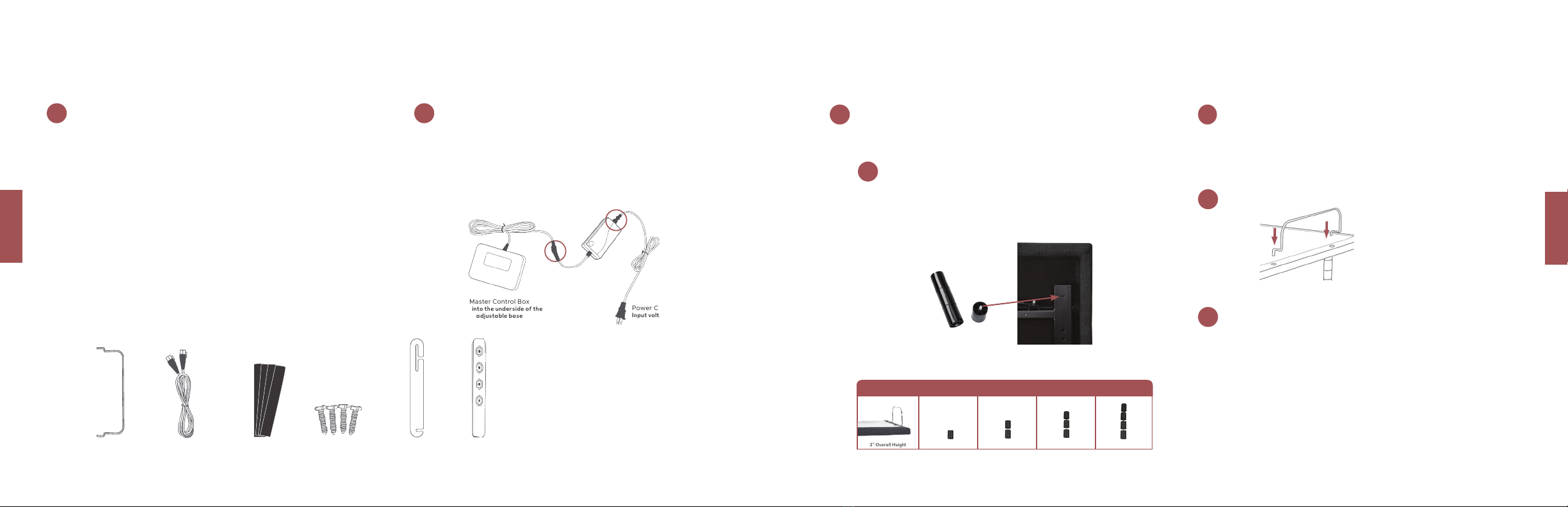
ZERO CLEARANCE 1 SEGMENT 2 SEGMENT 3 SEGMENTS 4 SEGMENTS
3” Overall Height 6” Overall Height 9” Overall Height 12” Overall Height 15” Overall Height
ADJUSTABLE BASE HEIGHT OPTIONS
SETUP GUIDE
OPEN AND UNPACK
Lay the box flat, open the box and unpack the list of components.
No tools are required for assembly.
COMPONENTS
(1) Remote
(3) AAA Batteries
(6) Adjustable Legs
(1) Power Cord
(1) AC/DC Power Adapter
(1) Power Cord
(1) Emergency Battery Strip
(1) Mattress Retainer Bar
(4) Hook and Loop Securing Straps
(4) Securing Screws
TWIN XL/CKS SIZES ONLY
(1) Synchronization Cord
(1) Connecting Straps
Synchronization Cable
Mattress Retainer Bar
Connecting Strap Emergency Battery
Strip
Hook and Loop
Securing Straps
Securing Screws
SETUP GUIDE
1POWER CORD ASSEMBLY
Locate the control box built into the underside of the adjustable base. Connect
the control box power cord, the AC/DC Power Adapter, and the Power Cord.
Store the Emergency Battery Strip in a safe location in case of a power outage;
two 9-Volt batteries are required for operation and are not included.
2
SETUP
SETUP
Master Control Box
Built into the underside of the
adjustable base
AC/DC Power Adapter
Power Cord
Input voltage 100-240V
CUSTOMER SERVICE 1-877-622-6550 FROM 7:30AM TO 5:00PM PST MONDAY-FRIDAYCUSTOMER SERVICE 1-877-622-6550 FROM 7:30AM TO 5:00PM PST MONDAY-FRIDAY
PAGE 8PAGE 9REMOTE
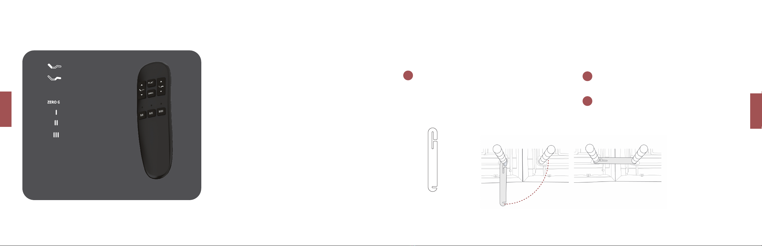
REMOTE
Head: Up/Down
Foot: Up/Down
Flat Preset
Zero Gravity Preset
Memory Button I
Memory Button 2
Memory Button 3
The remote control is pre-programmed to work with the adjustable base. If you
have more than one adjustable base, each remote control and adjustable base
set will work separately.
F L AT
M
M
M
MEMORY BUTTONS
To program a memory button:
move the adjustable base into
a desired position, then hold
the memory button down for
5 seconds.
SETUP
SETUP
With the adjustable bases in their desired location, slightly loosen both legs to
allow the strap to fit on the leg bolt, between the leg and frame.
(A)
(B)
CONNECTING STRAPS
Slide side (A) of the Connecting Strap onto the leg bolt. Swing the strap and
connect side (B) to the leg bolt. Secure the strap by shifting to the left.
Re-tighten legs. Do not over-tighten. Use the remaining strap and repeat on
other end of the adjustable base.
12
3
CONNECTING STRAPS
OPTIONAL FOR SPLIT KING OR SPLIT CAL KING ADJUSTABLE BASE SETS
The Connecting Straps will join two adjustable bases together to prevent drifting apart if they are not used within a bedframe.
CUSTOMER SERVICE 1-877-622-6550 FROM 7:30AM TO 5:00PM PST MONDAY-FRIDAYCUSTOMER SERVICE 1-877-622-6550 FROM 7:30AM TO 5:00PM PST MONDAY-FRIDAY
PAGE 10 PAGE 11
SETUP
SYNCHRONIZATION CABLE
SYNCHRONIZATION CABLE
OPTIONAL FOR SPLIT KING OR SPLIT CAL KING ADJUSTABLE BASE SETS
SETUP
Secure the adjustable base to the slat system by placing two Hook and Loop Securing Straps at the head and two at the foot.
Optional step for added security: Securing Screws are included to drill through wood on a bedframe to secure the adjustable base.
1
2
The Hook and Loop Securing Straps and Securing Screws are for zero clearance applications to secure the adjustable base to a bedframe slat system.
HOOK AND LOOP SECURING STRAPS
HOOK AND LOOP SECURING STRAPS
2
3
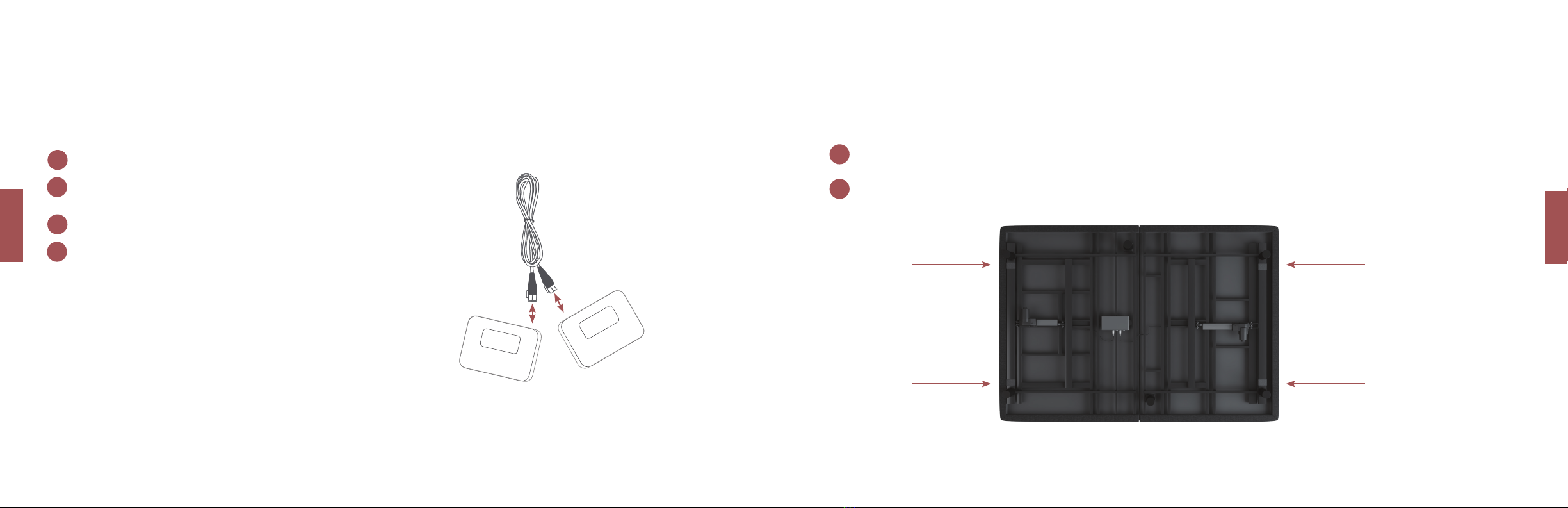
1Unplug the adjustable bases from the power outlets.
Connect the Synchronization Cable to the Master Control Box on each
adjustable base. Only one synchronization cable is required.
Plug the adjustable bases back into the power outlet.
Check to ensure all cords are securely attached. Both remotes will now operate
both adjustable bases simultaneously.
The synchronization cable will link two adjustable bases in movement and features.
Master Control Box
Built into the underside of the
adjustable base
Master Control Box
Built into the underside of the
adjustable base
Synchronization Cable
4

CUSTOMER SERVICE 1-877-622-6550 FROM 7:30AM TO 5:00PM PST MONDAY-FRIDAYCUSTOMER SERVICE 1-877-622-6550 FROM 7:30AM TO 5:00PM PST MONDAY-FRIDAY
PAGE 12 PAGE 13
FULL 1-YEAR WARRANTY
The Adjustable Base is warranted against defects in materials or workmanship for a
period of one year from the date of purchase to the original purchaser. During the first
year, manufacturer will repair or replace any defective part at no cost to the original
purchaser. This includes all authorized labor and shipping costs incurred with the repair
or replacement of any parts found to be defective.
2-YEAR LIFT MOTOR WARRANTY
The Adjustable Base has a two-year, full replacement warranty on the lift motors.
This includes labor and shipping, should the motor(s) fail during the first two years
of this warranty from the original purchase date.
5-YEAR WARRANTY
Year 2 through year 5, from the original purchase date, manufacturer will repair or
replace any defective part at no cost to the original purchaser. The part must be
returned within fourteen (14) days of receipt of the replacement part(s) or purchaser
may be subject to charges for said part(s) to include, but not limited to, freight charges.
Liability of manufacturer is limited to the replacement of the defective part or parts
ONLY, with purchaser responsible for all service, installation and transportation costs of
said part(s).
10-YEAR LIMITED WARRANTY
Year 6 through year 10 from the original purchase date, manufacturer will replace, per
the terms and conditions set forth in this paragraph, any Adjustable Base part found
to be defective. Any replacement part will be prorated at the discretion of South Bay
International. This warranty applies only to replacement part(s). Purchaser may be
subject to charges for said part(s) to include, but not limited to, freight charges. Liability
of manufacturer shall be limited to the replacement of the defective part(s) only, with
purchaser responsible for all service, installation and freight costs of said part(s).
10-YEAR LIMITED WARRANTY
ADDITIONAL TERMS AND CONDITIONS
Warranty does not include reimbursement for inconvenience, removal, installation,
setup, loss of use, shipping, or any other costs or expenses not expressly covered in this
warranty.
THIS WARRANTY DOES NOT APPLY:
* To damage resulting from misuse or abuse caused by the purchaser.
* To damage caused by the repairs or parts replacement by an authorized person.
* If the Adjustable Base has been mishandled subject to physical abuse or an
improper power supply, or otherwise operated in a manner inconsistent with
procedures outlined in the owner manual and warranty.
* To damage to mattresses, bedding, cables, electrical cords, or accessories
supplied by dealers.
* To modification of the Adjustable Base without prior written consent by
manufacturer.
* To costs for unauthorized service calls for the purpose of educating the
consumer about the Adjustable Base or locating properly functioning power outlets.
* If the weight limits are exceeded.
* If used in any environment or commercial setting for which it was not intended.
Some states do not allow the exclusion of incidental or consequential damages;
therefore the above limitation or exclusion may not apply. This warranty gives
the purchaser specific legal rights. The purchaser may have other rights, which may
vary from state to state. This warranty is valid in the 48 contiguous states.
WORKING WEIGHT LIMITS
Although your Adjustable Base has been rigorously tested within the recommended
limits in this publication, to maintain the highest quality standards, exceeding the weight
limits may void your warranty. The weight limit is 750 lbs. evenly distributed across the
Adjustable Base including the combined weight of mattress and users.
WARRANTYCHILD SAFETY LOCK
CHILD SAFETY LOCK
OPTIONAL
SETUP
1
2
Press “FLAT” and “Head UP” simultaneously for 4 seconds. When the remote
flashes twice the child safety lock is on. The adjustable base will not respond
when you press any button; the backlight will flash two times to remind you the
child safety lock is on.
To turn off child lock: Press “FLAT” and “Foot up” simultaneously for 4 seconds.
The backlight will flash twice when the child safety lock is turned off.
To lock movement of the adjustable base while using the remote, follow the instructions below.
WARRANTY

CUSTOMER SERVICE 1-877-622-6550 FROM 7:30AM TO 5:00PM PST MONDAY-FRIDAYCUSTOMER SERVICE 1-877-622-6550 FROM 7:30AM TO 5:00PM PST MONDAY-FRIDAY
PAGE 14 PAGE 15
TROUBLESHOOTING
TROUBLESHOOTINGTROUBLESHOOTING
TROUBLESHOOTING
TROUBLESHOOTING
TROUBLESHOOTINGTROUBLESHOOTING
TROUBLESHOOTING
TROUBLESHOOTING
TROUBLESHOOTING
TROUBLESHOOTINGTROUBLESHOOTING
TROUBLESHOOTING
TROUBLESHOOTING
TROUBLESHOOTINGTROUBLESHOOTING
TROUBLESHOOTING
TROUBLESHOOTING
TROUBLESHOOTING
IF ONE OR MORE FUNCTIONS ON THE ADJUSTABLE BASE HAVE
STOPPED OPERATING
* Check under the adjustable base to verify that the wired connections are secure and
that there are no cords or bedding obstructing the movement of the adjustable base.
* Check if the power cord is assembled properly and all the connections are secure.
* Check if the green LED is on the AC/DC power adapter is illuminated.
IF THE LIGHTS ON YOUR REMOTE CONTROL NO LONGER ILLUMINATE
AND WILL NOT OPERATE YOUR ADJUSTABLE BASE
* Make sure the batteries are installed correctly.
* Install three new AAA batteries in the remote control.
IF THE REMOTE CONTROL BUTTONS ILLUMINATE BUT ADJUSTABLE
BASE WILL NOT OPERATE
* Unplug the adjustable base for 5 minutes to reset the electronic components.
* Plug the adjustable base into a different electrical outlet, or test the current
outlet with another working appliance (a grounded, electrical surge protector is
recommended).
* If the steps above do not fix the issue, you can reset your remote frequency by
following the REMOTE FREQUENCY RE-PAIRING in the troubleshooting section.
IF YOUR PRESET POSITION IS NOT WORKING PROPERLY
* Reset your remote preset positions by holding down the zero gravity and flat position
button for 7 seconds.
IF THE HEAD OR FOOT MECHANISMS WILL ELEVATE BUT WILL NOT
RETURN TO THE FLAT POSITION
* Check the undercarriage for obstructions. Remove any obstructions away from the
head and foot mechanisms and return the adjustable base to its flat position.
REMOTE FREQUENCY RE-PAIRING
The remote is pre-programmed to the adjustable base, however if the remote is
unresponsive, follow these steps:
* Check the batteries; replace if needed.
* If the remote illuminates: Unplug the power cord from the outlet.
* Wait 5 seconds plug it back into the outlet.
* Wthin 10 seconds of plugging the power cord into the outlet: Press the “head up” and “foot
down” button at same time for 10 seconds, the adjustable base will be re-paired with
the remote.
TROUBLESHOOTING
POWER OUTAGE – EMERGENCY BATTERY STRIP
In case of an electrical outage, the Emergency Battery Strip allows you to operate the
adjustable base without power to your home. Only use the Emergency Battery Strip to
lift or lower the adjustable base into your desired sleeping position.
* Disconnect the adjustable base(s) from the power outlet.
* Locate the Emergency Battery Strip and install two 9-volt batteries.
* Attach the Emergency Battery Strip to the power cord.
* After the electricty is restored, the Emergency Battery Strip must be removed
before plugging the adjustable base back into the power outlet.
WARNING: Using the Emergency Battery Strip while the adjustable base is plugged
into a power outlet may cause the electrical components to short out and damage the
Master Control Box.
TROUBLESHOOTING
Emergency Battery Strip
Master Control Box
Mounted under the adjustable base
CUSTOMER SERVICE 1-877-622-6550 FROM 7:30AM TO 5:00PM PST MONDAY-FRIDAYCUSTOMER SERVICE 1-877-622-6550 FROM 7:30AM TO 5:00PM PST MONDAY-FRIDAY
PAGE 16 PAGE 17
TROUBLESHOOTING
TROUBLESHOOTINGTROUBLESHOOTING
TROUBLESHOOTING
TROUBLESHOOTING
TROUBLESHOOTINGTROUBLESHOOTING
TROUBLESHOOTING
TROUBLESHOOTING
TROUBLESHOOTINGTROUBLESHOOTING
TROUBLESHOOTING
TROUBLESHOOTING
TROUBLESHOOTING
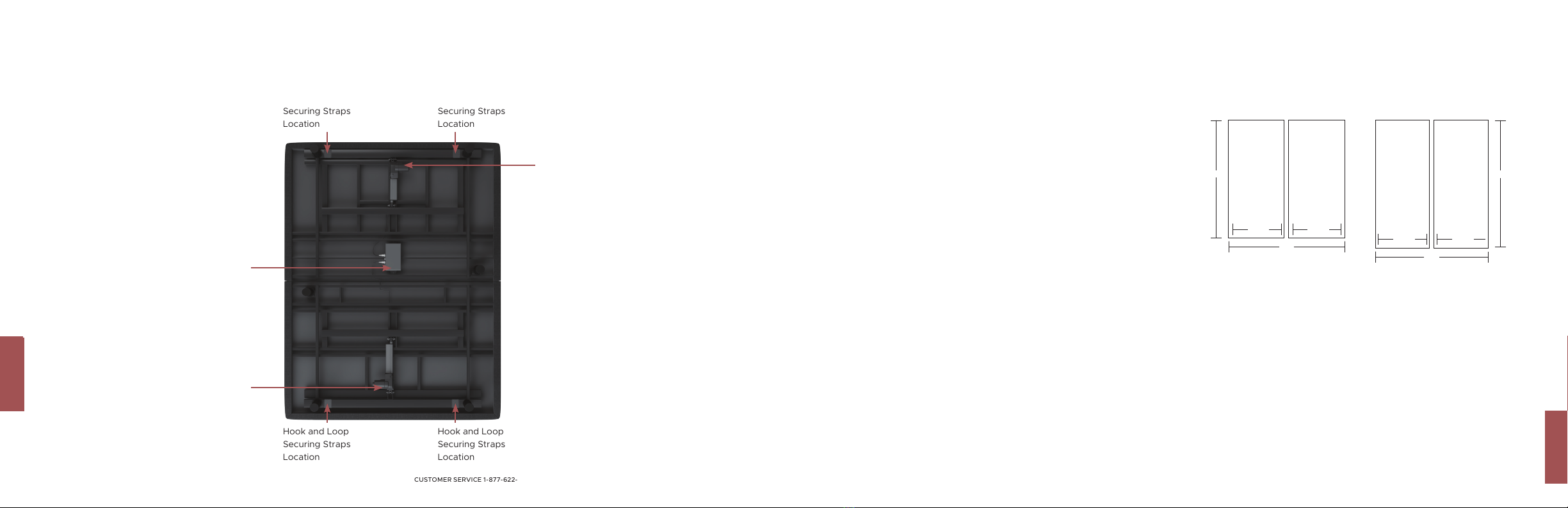
REFERENCE GUIDE
REFERENCE GUIDE
Foot Actuator
Master Control Box
Head Actuator
Hook and Loop
Securing Straps
Location
Hook and Loop
Securing Straps
Location
Hook and Loop
Securing Straps
Location
Hook and Loop
Securing Straps
Location
FAQFAQ
FAQ
FAQ
WILL THE ADJUSTABLE BASE FIT INSIDE MY CURRENT BED FRAME?
Yes, we designed the adjustable base width and length to be 1/2” shorter than standard
bed sizes to ensure the adjustable base fits within most bed frames.
ADJUSTABLE BASE DIMENSIONS
Twin XL: 37.5”W x 79.5”L x 15”H
Full: 53.5”W x 73.5”L x 15”H
Queen: 59.5”W x 79.5”L x 15”H
Split King: (x2) 37.5”W x 79.5”L x 15”H
Cal King Split: (x2) 35.5”W x 83.5”L x 15”H
WHERE CAN I PURCHASE ACCESSORIES?
Call Customer Service for additional parts or accessories such as headboard/footboard
brackets, split top adapter, additional remotes, specialty bedding, etc; sold separately.
WHAT SHEET SIZE DO I PURCHASE FOR A SPLIT KING OR CAL KING
SPLIT MATTRESS?
Eastern Split King (EKS): Eastern King Split Sheet Set OR (2) Twin XL Sheets.
Cal King Split (CKS): Cal King Split Sheet Set.
SEE DIAGRAM TO THE RIGHT
EASTERN KING SPLIT (EKS) CALIFORNIA KING SPLIT (CKS)
California King
Split
Twin XL or
Twin Long
California King
Split
Twin XL or
Twin Long VS.
Overall sleeping surface area is the same in the EKS and CKS.
The EKS is wider by 4” and the CKS is longer by 4”.
72”
76” 36”
84”
80”
38” 38”
36”

NOTES:
NEED TO TALK TO OUR COMFORT EXPERTS?
CALL 1-877-622-6550
CUSTOMER SERVICE HOURS: MONDAY THRU FRIDAY FROM 7:30AM TO 5:00PM PST
(ENGLISH AND SPANISH)

Other South Bay International Indoor Furnishing manuals

Popular Indoor Furnishing manuals by other brands

Regency
Regency LWMS3015 Assembly instructions

Furniture of America
Furniture of America CM7751C Assembly instructions

Safavieh Furniture
Safavieh Furniture Estella CNS5731 manual

PLACES OF STYLE
PLACES OF STYLE Ovalfuss Assembly instruction

Trasman
Trasman 1138 Bo1 Assembly manual

Costway
Costway JV10856 manual


