manuals.online logo
Brands
  1. Home
  2. •
  3. Brands
  4. •
  5. South Coast Sailplanes
  6. •
  7. Toy
  8. •
  9. South Coast Sailplanes Voltij User manual

South Coast Sailplanes Voltij User manual

1
Voltij
Voltij is a sailplane any fibre revolutionary intended for the stunt-flying sailplane. It has a
symmetrical profile especially calculated for the use of the elevators and a piloting 4 axes. This
profile enables him to be as powerful invertedas at the place. By using the elevators, it sands
easily what makes it possible to quickly gain altitude to carry out a program of stunt-flying. The
mixing depth towards elevators also enables him to take load factors raised without starting, which
allows a tonic stunt-flying. It is necessary at the time construction to bring it a care very particular
to the commands for are without play to have the precision necessary in stunt-flying. The control
surfaces will have to be produced semi-tight as indicated in this note. Painting is painting of an
acrylic type which does not like solvent. It is necessary to avoid alcohol and other white spirit. Best
it is the soapy water. For the Scotch tape traces WD40 cleans good. The duration of construction
is 15 to 20 hours.
Caractéristiques Techniques
Span: 2020 mm
Cords : 250, 110 mm
Surface : 36 dm2
Profil : MG 05 à 9%
Length :1250 mm
Weight : 1600 g
Ballast : 200g
Charge alaire : 44, 50 g/dm_
Radio: 4 servo de taille standard et de bonne qualité
1 accu 4 ou 5 éléments 1400mA
1. Liste des Accessoires
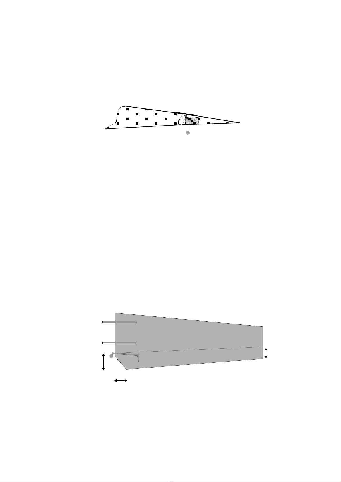
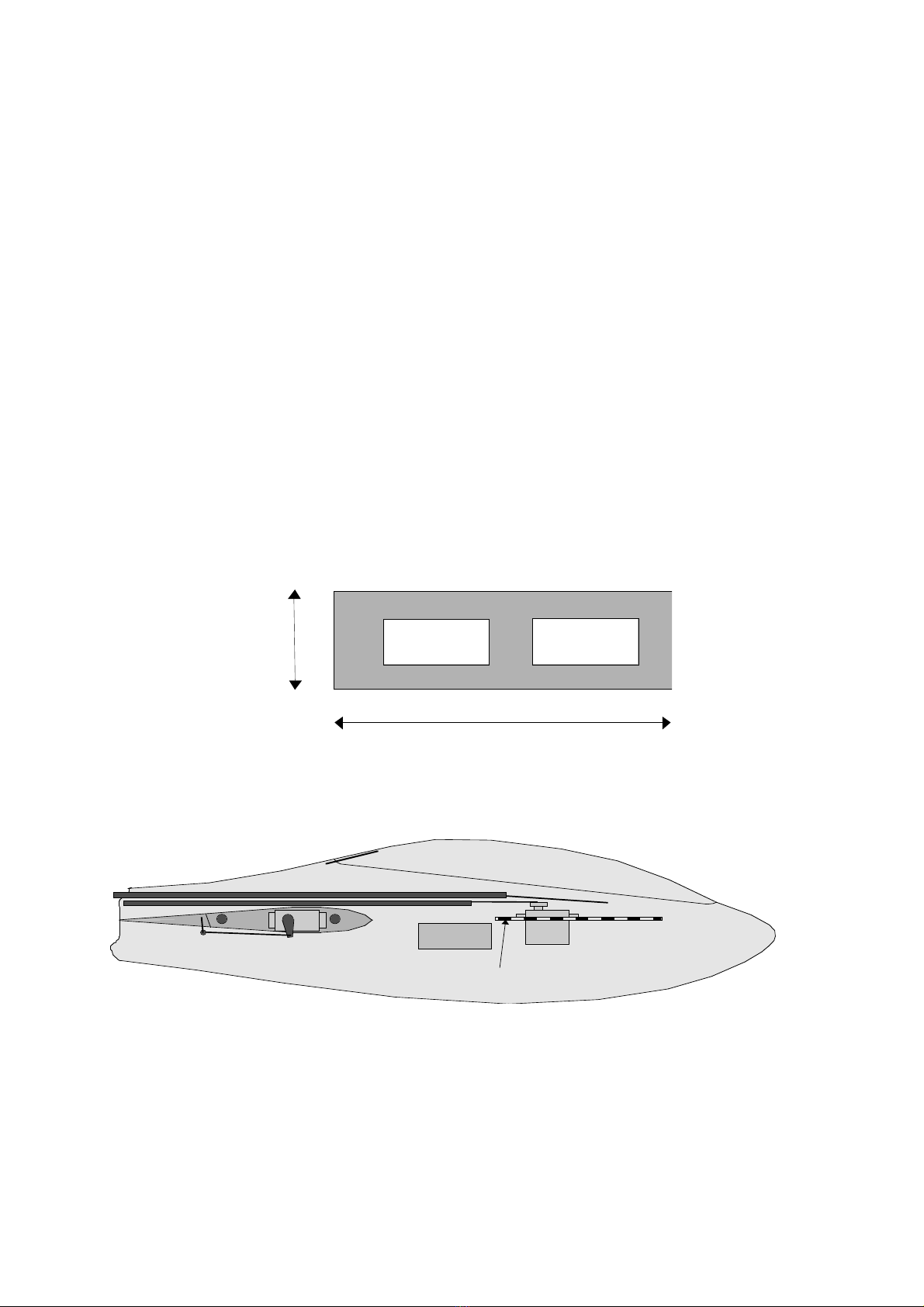
1 platine servo en CTP aviation de 20/10 d’environ 150mm x 42mm
4 chapes à mâchoire coté servos
2 chapes à boules coté ailerons
1 chapes à mâchoire coté dérive
1 chapes à mâchoire coté stab (option stab pendulaire)
2 chapes à boules coté stab (option stab à volets)
6 ou 7 tiges filetées M2 pour les commandes d’aileron, et les tringles
2 tubes de carbone diamètre 6mm pour les tringles de dérive et de stab (chez Décathlon)
2 renforts en CTP 20/10 de 10x10 pour recevoir les guignols d’ailerons
2 renforts en bois dur de 15x15x5mm pour le renvoi de stab ou un bloc de 50x16x15mm pour le stab à
volets
16 petites vis à bois pour la fixation des servos dans le fuselage
Balsa 30x20x4mm pour le raidisseur de dérive
2 cordes à piano de 2mm x 80 mm pour la fixation de la verrière
1 rouleau de scotch charnière
1 tube de colle silicone pour les charnières
2 cordes à piano de 2mm x 100mm pour les clés de stab (fournis)
2 tubes laiton de diamètre intérieur de 2mm x 17mm pour les fourreaux de stab (fournis)
2 clés d’aile Carbone de diamètre 8mm x 250mm( fournis)
En option : 2 clés d’aile acier de diamètre 8mm x 250mm
2
2. Construction of Ailerons
2.1 Découpe des ailerons et du volet central
The ailerons make 7.5 cm (30% of the cord) on the level of the root and 3.3 cm with tip. The
ailerons are full span and go to tip.
The cutting of the ailerons is made with the cutter (new blade) metal length un reglet. It is
necessary to make several light passages by taking guard not to slip with the reglet. One can
scotcher the reglet on l?aile to be on qu?il does not slip, or to better stick a Scotch tape of
electrician inverted of the reglet what enables him to adhere. Attention, finally, with the root cutting
under-surface must be about 4 mm more before cutting top profileand 1.5mm with tip.
3.3 cm
7.5 cm
Vérifier que le débattement vers le
bas s’obtienne par glissement de
l’intrados de l’aileron sous
l’intrados de l’aile. Au besoin
poncer un peu pour qu'il n'y ait pas
de frottements.
3 : Scotcher l’aileron et appliquer, par
le dessous, avec un seringue un
joint de colle silicone au niveau de la
charnière en repoussant l'aileron
à90°. Laisser sécher aileron au
neutre.
2 : poncer en creux avec une cale et
du papier de verre. Raccourcir
l’intrados d’un demi millimètre
1 : Marquer la bonne longueur et
découper la peau au cutter
(extrados puis intrados)
Largeur de découpe
spécifiée
3
2.2 Installation des guignols d'ailerons
Installation of the control horns is done classically. We recommend ball links for an easy assembly
on the ground and any running clearance. It is necessary to insert and stick a small hard wood
parallelogram in l?aileron in which will be screwed and stuck the control horn. For the ailerons it is
necessary to envisage a 10 mm top control horn which this finds to 20 mm of the wing root and on
the equal to the hinge to avoid introducing an awkward mechanical differential.
2.3 Installation of ailerons servos.
We recommend to install both servos will ailerons on the section of each karman fuselage. This
operation is detailed in the fuselage part.
2.4 Locking of the wings
The wings can be locked in flight by Scotch tape on the karmans but it is more aesthetic to make
a small device with 2 hooks and a rubber band.
3. Le stab
Two versions are possible: Stab with pendular control surface or stab. The pendular stab is simpler
to realize but some prefer the linearity of a stab with elevators. In the 2 cases, it is necessary to
saw has 45° the interior corner of each stab to allow the clearance of the rudder.
3.1 Cut out elevators (Option stab with elevators only)
For the cutting of the elevators, the method is exactly the same one as for the ailerons. According
to following dimensions:
For sticking the Scotch tape and making the joint silicone it is necessary to install the control horns
2 cm
3.5 cm
2.5cm
4
3.2 Installation of the control horns(Option stab with elevators only)
The control horns are made starting from piano wires of 2mm of diameter. It is necessary abord to
cut 2 pieces of CAPE of 6cm length, to bend them to 1.2 cm with 90°. On the bent ends, it is
necessary to fix in force and to weld or stick a ball link to ball. To fold the other end in the control
surface. To stick this fast end with époxy in the control surface by putting a hinge out of
provisional Scotch tape. Once gone up the command of the stabs will be as follows:
1.2 cm
Dérive
Vue de derrière
3
cm
To finish the stabs by scotchant the hinges and by applying a joint silicone...
4. Rudder
4.1 Capping thje rudder
To cut out a piece of balsa with following dimensions:
To stick to the cyano in the rudder with the short-nap cloth of the foot.
4.1 Installation control horn of rudder.
It is necessary to stick the control horn of rudder compared to the output of command envisaged
in the fuselage, to make for that a small hole in the rudder, to dig polystyrene a little and to stick
the control horn to epoxy by filling well the hole in polystyrene
4.2 Articulation of rudder.
Polystyrène
Longerons en
Balsa de 40/10
Guignol
5
The rudder is articulated by a Scotch tape on the with dimensions right of the fixed plan. One can
also place a thread of silicone on the articulation to decrease the play.
5. The fuselage
5.1 Installation of the sleeves of key of stab (Option stab with elevators only)
To make 1 small hard wood parallelepiped with dimension following: 50mm X 16mm X 15mm. To
sand the interior of the foot of rudder, with the height of the stab so that the adhesive hangs and
to stick to epoxy the small piece of wood by tightening the rudder with a greenhouse joint. To bore
2 holes of 3mm, through the rudder and wood, at the places indicated on the left side of the
rudder, by paying great attention to perpendicularity with the plan of the rudder. With the need to
use a drilling machine on foot and to fix the fuselage horizontally. To cut 2 brass tubes of 3mm to
the good length and to stick these sleeves, to the cyano, in the rudder.
3.5 cm
1.0 cm
1.0 cm
Bloc de bois dur
5.2 Passage of the control horns of stab
To be able to thread the stabs on the ground it is necessary to bore an enough large passage to
them to be able clipper the covers with balls since outside.
5.3 Installation of the sleeves of key of stab (pendular Option stab only)
To make 2 small hard wood parallelepiped with dimension following: 15mm X 15mm X 5mm. To
bore in their center with the diameter 3mm. To assemble the 2 pieces and the bevel gearbox with
a brass tube of 3mm of diameter and 18mm length while letting exceed the tube of 1mm of each
with dimensions. To boron well perpendicularly the holes before (3mm) with the level of the mark
one the left blank of the rudder transistor. To sand the interior of the foot of rudder transistor, with
the height of the stab so that the adhesive hangs. To stick to epoxy the small pieces of wood
assembled on the bevel gearbox by tightening the rudder with a greenhouse joint.
6
3.5 cm
1.0 cm
Bloc de bois dur
It is then necessary to mill an oblong passage for the 2nd key of stab so that the stab can discuss
without hanging.
5.4 Montage du raidisseur de dérive
To cut out the stiffener member out of balsa of 40/10 with following dimensions:
20 mm16 mm280 mm
To sand with the large sandpaper the interior of the rudder and to stick the stiffener to the cyano
in the fixed part of the rudder to 8 mm in withdrawal of the left edge once that the reference of
depth, rods etc... are finished and installed.
5.5 Installation of the wing rod tubes.
This work is delicate because it is necessary that the 2 wings are connected perfectly with
Karmans of the fuselage. It is a question of sticking the 2 aluminum sleeves in Karmans. For that
to proceed as follows:
To take a print of the wing root, by firmly pressing a paper A4 sheet on the root. Thus will appear
in the sheet and in relief the contour of the profile as well as the holes of the keys of wings. To
then use the print of the left wing on the karman right and vice and poured. Paper in relief then
will marry perfectly the karman fuselage, which makes it possible to mark with a punch the centers
of the holes of keys of wing through paper. The centering of paper on Karman is rather easy into
vertical but into horizontal it should be paid attention more so that the holes fall well opposite. To
then pre-bore with the diameter 5mm the 4 holes and to slip inside of the stems to check their
parallelisms and their perpendicularities in all the axes. To then thread tubes of interior diameter
8mm external and 5mm on these stems and to check good sliding motion in the sleeves of the
wings. Then to increase the holes with the drill of 9mm if they are well centered or with the round
file if should be caught up with some shifts. The sleeves aluminum must then re-enter a little in
force. To once again check parallelisms, perpendicularities and sliding motion with the wings
assembled with their keys.
To then stick the sleeves to the cyano to immobilize them. Then, it is necessary to ensure their
joining with sauerkraut of glass fibre and resin epoxy. For that to proceed in 2 times. To sand the
7
interior of the karman with large sandpaper so that the resin clings, scotcher the outside of the
karman right to prevent that the resin does not run out, choucrouter and to let dry the fuselage
laid down on the right blank. To make in the same way with the karman left.
5.6 Fixing of the canopy
Each one with its practices for fixing of canopy, if not a good method and joining with epoxy of 2
small piano wires of 2mm X 80mm to front and the back. To sand the canopy for joining well and
to fold the part to be stuck of the CAPE as a guy zag for a better joining. The exceeding CAPE of
2-3mm are wedged then under the edge of the fuselage while making slide the canopy.
6. Installation radio
The fuselage receives the 4 servos of standard size of the stab, the rudder, of the ailerons, the
receiver and an accumulator 4 or 5 elements 1400mAh. While placing l?accu well in the nose one
should arrive at the centering recommended with a minimum lead addition (< 50g)
6.1 Installation of the servo tray.
To make a servo turntable in ctp of 20/10 with following dimensions:
Taille Servo
standard
150 mm
42 mm
To sand the interior of the fuselage so that the adhesive hangs and to stick platinize it at the
place indicated on the diagram with epoxy resin. It is preferable to install platinizes it radio with the
same height as the wing for a better dynamic balance of the sailplane.
CAP 20/10
de fixation
de verrière
Platine servo CTP 2mm
Récepteur
Accu
5x1400mA
6.2 Installation of the servos will ailerons
Both servos will ailerons s?installent on the section of each karman. There the fibre is sufficiently
thick between the 2 keys ailes to be able to screw servo of standard size directly. It is enough for
that to découper/fraiser the karman and to bore 4 small holes in fibre for the screws. The head
8
and the top of servo then exceed karman in the panel of wing which must also be dug
consequently. The skin under-surface must then be cut out in T to let pass the control horn during
the assembly of l?aile and its operation. This installation has the advantage not weakening l?aile,
éviter an additional connector and of keeping inertias in the center what is significant for the stunt-
flying. During the assembly - disassembling of the wings on the ground it is enough then to clipser
- déclipser the cover with ball of l?aileron.
6.3 Tringles de commande
The rods of ailerons are simple threaded rods is necessary to cross to the good length. The fine
adjustment will be made servos installed by screwing - unscrewing of the covers. The 2 rods of
depth and rudder will be made out of carbon tube of 6mm of diameter with inserts of threaded
rods with each end stuck to l?époxy. In the case of a stab with control surface it is necessary to
insert 2 threaded rods length identical with 2 covers to ball of with dimensions of the stab to form
Y and thus to control the 2 elevators at the same time. Sufficient carbon stems of 6 c?est (it will
not flame). If one is finicking one can install a couple with 2 holes of 7mm to the top of the back
key of wing to guide the stems a little.
7. CG
Neutral centering is to 105 mm of the leading edge. With an accumulator of 5x1400mAh, it almost
does not require lead. For the first flights one can advance the centering of 10mm c?est-with-
statement to put 30g moreover in the nose.
8. Control movments and mixers.
Positive values = donward movnent of the control surface in question. This sailplane being entirely
symmetrical one needs also symmetrical movment upwards and downwards on all the control
surfaces. Movment given here give a very nimble sailplane on all the axes. It is strongly advised to
use these movment only with a good amount of exponential (30 to 50%) what makes it possible to
keep the precision of piloting necessary for a clean stunt-flying. The dynamic flaps correspond to a
mode of piloting 4 axes, with saying the flaps on the gas handle to which one removed the rachet
Elastique
Guignol
d’aileron
Aileron
Aile
Découper
la peau
d'intrados
Creuser le
polystyrèn
e
Clé d’aile
arrière
Fuselage
Clé d’aile avant
9
and the return spring. The symmetrical profile conceived specifically for the flaps, it is essential to
use a mixing elevator towards flaps to accept significant load factor.
Elevator with flaps: +7 mm / - 7 mm
All moving Elevator: +14 mm / - 14 mm
Rudder +35 mm / -35 mm
Ailerons: +30 mm / -30 mm not of differential
Camber +6 mm
Reflex (inverted camber) -6 mm
4 Axis Flying: +20 mm / -20 mm
elevator to flaps: +10 mm / -10 mm
Air-brake: -30 mm
Elevator compensation to pull up air-brake: + 50%
9. Vols
9.1 First flight
The first flight will be done without ballast, all the control surfaces exactly with the neutral,
centering with 95mm of the Leading edge. The panels being locked with the fuselage by a rubber
band or Scotch tape along the joint. We also advise to accomplish the first flights with the Dual
rate to 50 % out of the 4 axes to be accustomed gradually to the astonishing handiness of this
sailplane. Attention this sailplane being symmetrical will tend to prick slightly at the place as on the
back. One then can elevator trim at the place and stitcher on the back, but it is preferable to
support it with the camber what makes it possible profile of the good value.
9.2 Flights following
To move back centering with 100mm of the attaque edge according to your impressions.
Reasonable back limit being 105mm. To start to familiarize itself with the sailplane before
increasing clearances with the values indicated.
9.3 Ballast.
Ballasting is not of primary importance on Voltij. It is for that that no tube with ballast was
envisaged. Nevertheless by strong wind one can replace the keys of wings carbon by keys steel
8mm what corresponds to + / - 200g of ballast. The sailplane is then faster and the figures more
ballistic and less tight

Popular Toy manuals by other brands

RM Super Sky Surfer 2000 Assembly instructions

RM

RM Super Sky Surfer 2000 Assembly instructions

marklin 37082 user manual

marklin

marklin 37082 user manual

Value Hobby 48in EPP MXS ARF Instrucition manual

Value Hobby

Value Hobby 48in EPP MXS ARF Instrucition manual

LGB 24211 instruction manual

LGB

LGB 24211 instruction manual

Jamara Atlantique Instruction

Jamara

Jamara Atlantique Instruction

Textron Cessna SKYHAWK Information manual

Textron

Textron Cessna SKYHAWK Information manual

Fisher-Price X7759 manual

Fisher-Price

Fisher-Price X7759 manual

Opitec Hobbyfix Flip manual

Opitec

Opitec Hobbyfix Flip manual

Faller PLASTER SILO AND BUILDING-SITE TRAILER Assembly instructions

Faller

Faller PLASTER SILO AND BUILDING-SITE TRAILER Assembly instructions

Playskool Chip Chainsaw instructions

Playskool

Playskool Chip Chainsaw instructions

Fisher-Price X6172 manual

Fisher-Price

Fisher-Price X6172 manual

iKarus bell 222 instruction manual

iKarus

iKarus bell 222 instruction manual

Jamara Ped Race instructions

Jamara

Jamara Ped Race instructions

Multiplex 21 4193 Building instructions

Multiplex

Multiplex 21 4193 Building instructions

Mattel Disney PIXAR LIGHTYEAR instructions

Mattel

Mattel Disney PIXAR LIGHTYEAR instructions

Seagull Models DECATHLON ARTF Assembly manual

Seagull Models

Seagull Models DECATHLON ARTF Assembly manual

Sharper Image VIRTUAL DISC BATTLE user guide

Sharper Image

Sharper Image VIRTUAL DISC BATTLE user guide

TOMAHAWK SPORT FOX 21100 instruction manual

TOMAHAWK SPORT

TOMAHAWK SPORT FOX 21100 instruction manual

manuals.online logo
manuals.online logoBrands
  • About & Mission
  • Contact us
  • Privacy Policy
  • Terms and Conditions

Copyright 2025 Manuals.Online. All Rights Reserved.