Titan ZG 45PCI-HV User manual

Toni Clark practical scale GmbH
TITAN ZG 45PCI-HV
GB
Instructions

©2012 Toni Clark practical scale GmbH Zeiss-Str.10 D-32312 Lübbecke Tel. 0049 5741/5035 Fax. 05741/40338 www.toni-clark.com
Instructions Titan ZG 45PCI-HV
2
5 years guarantee for TITAN model aircraft engines
More than 20 years experience with TITAN engines plus our quality control allows us
to extend the period of guarantee from one to ve years. This guarantee covers the
engine and the ignition only.
The following conditions must be met to obtain the guarantee:
Guarantee is for the rst owner only and is not transferable to any other person.
In the event of any claim, the engine must be returned to us with the original invoice.
The serial number on the crankcase must be undamaged, and must not have been
removed and reapplied. The serial number is registered by us with the buyers name
and the date of purchase.
The only fuel to be used is the petrol oil mixture as specied in the instruction manual.
Use of Methanol invalidates the guarantee.
The guarantee includes the Microprocessor Ignition unit, the maximum voltage of
9 volts must not be exceeded. Mechanical damage to the cables is not covered by
guarantee.
The guarantee is that we replace any defective parts free of all labour and material
costs and pay only the return postage and packing. This guarantee covers only the
engine and can in no way be construed to cover anything else.
This guarantee does not cover crash and related damage in any form whatsoever.

©2012Toni Clark practical scale GmbH Zeiss-Str.10 D-32312 Lübbecke Tel. 0049 5741/5035 Fax. 05741/40338 www.toni-clark.com
Instructions Titan ZG 45PCI-HV 3
Congratulations on your purchase of a Titan ZG 45PCI-HV
About the biggest problem facing man is that he does not know what he does not
know. To resolve this problem requires enormous eorts, however try to avoid so much
as possible unnecessary mistakes and please read the following pages carefully. Do
not take fright at the amount written here, it is really a list of mistakes many modellers
have made and you should at all costs avoid. A reliable running engine stands or falls
with the way you instal the engine in your model, and how you handle your engine.
It is up to you, to read and carry out these instructions, to have success and be able to
get real fun out of the hobby of ying model planes.
The Titan ZG 45PCI-HV, tted with the Microprocessor Ignition, will start just as easily
as with the Easy Start System. Although the starting technique is totally dierent to
the ZG 45SL with the standard magneto ignition and requires a fully new approach.
In other words, please forget all you have learnt with starting the magneto ignition
engine and follow the starting instructions for the Microprocessor Ignition, given
towards the end of this manual!
The Titan ZG 45PCI-HV is not a complicated engine, it is a well proven industrial two
stroke engine. To ensure your engine reaches you in perfect condition, we have specially
trained people to completely strip each engine down and thoroughly check it. This
stripping and reassembling takes between 25 and 30 minutes per engine and ensures
that you receive an engine that is mechanically sound as can be.
The Titan ZG 45PCI-HV is a very powerful engine, the thrust from the propeller is such
that you simply cannot aord to take any chances. You take a chance and you run the
risk of not only endangering yourself, but other people as well. Take care before each
start, double check to see the throttle is not on full power. If you do not have anyone
to help, you must anchor your model securely or ick the propeller over from behind
the engine, using the other hand to hold the model, this way you are in no danger
from the prop. A screwdriver stuck in the ground in front of each wheel is not only
useless, it is dangerous!
Do not taxi your model right back to the starting place on your ying eld, instead cut
the engine and push the model back! Pushing your model back, you may think seems
unprofessional. Forget such ideas! You never know, something might go wrong and
your model suddenly has full throttle! Should the result be that you have reduced your
club chairman’s model to its component parts, you can count yourself lucky if it’s not
the chairman himself, or his dog.

©2012 Toni Clark practical scale GmbH Zeiss-Str.10 D-32312 Lübbecke Tel. 0049 5741/5035 Fax. 05741/40338 www.toni-clark.com
Instructions Titan ZG 45PCI-HV
4
Rigid mounting
The rigid mounting of your engine has the attraction that it is cheap and simple. A well
constructed model can easily withstand the vibration. It is preferable to t the receiver
in a Balsa box with plastic sponge material as opposed to tting the receiver to a rigid
Balsa sheet with rubber bands or similar. It will certainly pay to buy more expensive
servos with better motors and potentiometers as these will withstand the vibration
without diculty. Whether the rigid mounting of the engine will cause more noise
depends largely on the covering. A really tightly shrunk silk, nylon or plastic heat shrink
material is to be avoided, for these coverings will act just like drum skin, amplifying
the sound from the engine.
For rigid mounting you have the choice between our three motor mounts #6590,
#6561 and #6552. Alternatively you can cut a motor mount from a 5 mm thick alu-
minium sheet. The four screw holes in the rear crankcase half are M6 and are 38 mm
equidistant. Secure the M6 mounting screws with either Loctite or spring washers.
If you use a aluminium sheet mount, you must of coarse cut a hole in the rewall to
take the rear crankshaft stub. No need to worry about oil getting into the fuselage,
the seal is absolutely oil tight.
Secure the motor mount in the well proven way with M5 socket screws, spring washers
and crown nuts in a 9 mm thick birch plywood rewall. If the rewall is hardly bigger
than the motor mount you can safely use 6 mm birch ply.
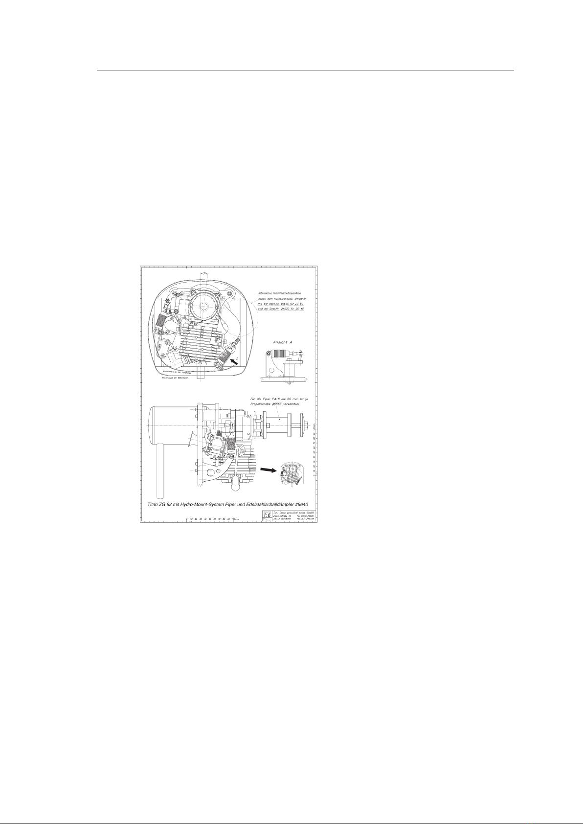
Hydro Mount System
When you wish to have a real quiet model and already have tried many would be
solutions, you will nd our three HMS variations will bring astounding results. Our
HMS uses two shock absorbers and four very soft rubber silent blocks, resulting in a
very satisfactory decoupling of the engine from the airframe. The soft rubber silent
blocks would not be possible without the shock absorbers. The swing amplitude of
these rubber mounts with the engine throttled back would be 15 mm and with such a
movement, a low speed tickover would be impossible, as the energy being absorbed
by the rubber mounts would not leave enough over torque wise to bring the propeller
over the next TDC. The use of harder rubber mounts to reduce the swing amplitude
would only be partly eective at full throttle.
The purpose of the two shock-absorbers is to dampen the torsional oscillations. The
shock-absorbers transmit some vibration from the engine into the airframe and this
cannot be avoided. The advantage of these shock-absorbers is that they are purely
dampening, without any form of springs, thereby it is impossible for them to come
into resonance. The shock-absorbers can be regulated in their action from hard to
soft by choice of oil viscosity. As opposed to various forms of xed rubber-covered
stops or similar to limit movement, the shock-absorbers are much quieter. With the
shock-absorbers you have the advantage of the airframe being eectively insulated
from the engine at full throttle with most torsional oscillation being dampened out
at the tickover.

©2012Toni Clark practical scale GmbH Zeiss-Str.10 D-32312 Lübbecke Tel. 0049 5741/5035 Fax. 05741/40338 www.toni-clark.com
Instructions Titan ZG 45PCI-HV 5
The shock-absorbers for our Hydro-Mount-System had to be specially designed and
manufactured, using hydraulic rod seals, as none of the already available shock-absorb-
ers could cope with the demands of being tted into our Hydro-Mount-System.
You will see that our shock-absorbers are nned to provide adequate cooling, (they
transform movement energy into heat), and tted with a rubber grommet, which
absorbs the very ne oscillatory movement at full throttle where the shock-absorber
is getting stier.
The HMS is a complete system, with four special rubber silent blocks, two shock ab-
sorbers, mounting brackets and rubber grommets for the shock absorber, all screws
nuts and washers and a ready formed spider leg engine mount are included.
The Hydro-Mount-System Piper is designed
to t into our Piper PA-18. The cylinder is
inverted and 7 degrees left from vertical.
The stainless muer is placed right behind
the crankcase and screwed to the aluminium
spider leg mount. The Hydro-Mount-System
Piper can be integrated in many other mod-
els, as long as the cowl is big enough to take
the engine.
Cooling air opening
For cooling the Titan ZG 45PCI-HV it is not necessary to have a specially large opening
in the cowl. But it is essential to ensure, that as much air as possible entering the cowl
ows through the nning and around the carburettor, which also needs cold air. Air
takes the path of least resistance and will not normally ow through the ns, unless
you take positive steps to force it to do so by means of air-ducting. Balsa sheeting and
blocks is the best material to use for this.
It is essential that the ducting almost makes contact with the engine, so balsa is bet-
ter than aluminium, for should the latter make contact with the engine, this can easily
cause severe radio interference due to metal to metal contact generated noise.

©2012 Toni Clark practical scale GmbH Zeiss-Str.10 D-32312 Lübbecke Tel. 0049 5741/5035 Fax. 05741/40338 www.toni-clark.com
Instructions Titan ZG 45PCI-HV
6
Ignition installation in the model
The most important rule covering battery ignition systems rst:
Never ever switch the system on without the spark plug cap being on the spark
plug!
Keep all parts of the battery ignition as far as possible from the receiver, mini-
mum distance being 15 cm.
The microprocessor Ignition is protected with a tough metal case and the electronics
inside are encapsulated to protect against vibration. In spite of this it is not a good idea
to simply mount the ignition box onto the rewall with a couple of cable ties.
Please t the cables very carefully into your model, especially the high tension cable,
as this will not contain the 21,000 volts if it is damaged due to scung against the
cowl inner surface. If the screening ex is damaged due to scung when threaded
through a GRP cowl opening, it will not be long before the inner insulation is damaged
also. Then the HT will short out to the screening ex and this may cause massive radio
interference and will of course lead to an ignition cutout.
Mechanical damage caused to the HT cable is not covered by the guarantee!
Switch
Use only knife edge contact switches such as our switch order no. #2024 or the Graupner
receiver cable with charger socket order no. 3046. Toggle switches with roller contacts
are not suitable as these are intended for 240 V. Used on low voltage, oxidation can
occur, this increases the contact resistance and will lead to ignition failure.
Take care with plugging together the JR-plugs and sockets by noting that the colours
should line up on opposite sides. It is possible with a little extra eort to push these
together with reverse polarity. No damage will be done but the ignition will of course
be dead. I tape these plugs and sockets with insulation tape for additional safety.
We recommend to secure the connection additionally witch tape!

©2012Toni Clark practical scale GmbH Zeiss-Str.10 D-32312 Lübbecke Tel. 0049 5741/5035 Fax. 05741/40338 www.toni-clark.com
Instructions Titan ZG 45PCI-HV 7
Ground connection of the ignition with rubber spark plug cap
Please attach the ground strap on the igni-
tion coil bracket on the crankcase. Because
of the insulator, the carburattor screws are
not suitable.
If a intake bend is used the one of the in-
take bend screws can be used to attach the
ground strap.
Please make a range test prior the rst ight.
Without a good ground connection severe interferings will occur!
Fit the pickup head with the power coil
screws as shown.
The ignition timing is automatically correct
and cannot (and need not) be adjusted.
The gap between the pickup and magnet is
not critical, it can be anything from 0,2 to 2
mm.
Looked at from the side, the pickup posi-
tion is even less critical, you see here the
middle position. Although 2 mm forwards
or backwards will work perfectly well. The
pickup is a tight t in the pickup mount and
secured with cyano. If the pickup is sitting
outside the tolerance, washers can be used
for packing between the pickup head and
the crankcase.
Pickup installation

©2012 Toni Clark practical scale GmbH Zeiss-Str.10 D-32312 Lübbecke Tel. 0049 5741/5035 Fax. 05741/40338 www.toni-clark.com
Instructions Titan ZG 45PCI-HV
8
Battery
With the new PCI-HV ignition we have set the greatest value on a really strong spark.
Of course, high- energy sparks are not possible without higher input power from the
battery, but we believe this is a fair price to pay. With modern battery technology, the
battery weight no longer matters, so why not go for the best possible starting, reli-
ability and performance?
The PCI-HV ignition contains a very ecient voltage converter, which is capable of us-
ing the higher voltage instead of converting it to heat, as in the case of the common
linear voltage regulators. With the PCI-HV ignition the rule is: the higher the voltage,
the lower the current. Therefor it is best to use a 2s LiPo directly, without an external
regulator, the ying time will be the longest.
Beside the 2s LiPo battery, there are quite a few other options. This can be a two cell
A123 or LiFePO4 battery. Also a 5 or 6 cell Sanyo Enerloop 2000 NiMh can be used.
Be warned, that if you go for a 4 cell NiCd or NiMH type, this has to be one with a low
internal resistance. When the voltage drops below 4.8 V, the engine will start to misre.
A 2s LiPo is rst choice for best capacity to weight ratio.
Current consumption single cylinder-ignition
PCI v1.HV
2000 1/min 6000 1/min 8000 1/min
5,0 V 300 mA 800 mA 1090 mA
5,5 V 270 mA 700 mA 920 mA
5,9 V 250 mA 660 mA 810 mA
6,6 V 220 mA 550 mA 750 mA
7,4 V 190 mA 490 mA 630 mA
8,4 V 170 mA 420 mA 550 mA
Current mA
RPM
RPM
RPM
RPM
Voltage V
Under normal conditions, you will not y at full
throttle and certainly not at 8000 RPM all the time,
therefor a 1000 mAh 2s LiPo battery is enough for
two hours ying with safety. The idle current with
engine stopped is approximately 30 mA. The PCI
ignition does no longer automatically shut down
when one minute has elapsed without the propel-
ler being turned. This safety switching in the past
has caused more frustration than doing any good.
Current
consumption in
relation of battery-
voltage and engine
speed

©2012Toni Clark practical scale GmbH Zeiss-Str.10 D-32312 Lübbecke Tel. 0049 5741/5035 Fax. 05741/40338 www.toni-clark.com
Instructions Titan ZG 45PCI-HV 9
Spark plug
The very robust Champion RCJ-7Y resistor plug is tted.
The contact gap is 25 thou or 0,6 - 0,7 mm.
Dierent long versions of RCJ-7Y Spark plugs are in existing!
The Titan ZG Engines are delivered with an
extra short version of the RCJ-7Y spark plug.
Only this "Bantam"-Version of the spark plug
ts into the Bosch spark plug cap! On the
commonly available type the Bosch cap can-
not be entirely pushed on. The cap looses it`s
ground contact and causes a spark gap on
the base of the spark plug. If you are lucky
the engine fails to start. In the last resort
severe interferings will occur.
Because of the fact, that the Bosch cap is tted with an resistor, spark plugs without
resistor can be used. The spark will be stronger. The name of the spark plug without
resistor is Champion CJ-7Y or NGK BPM7A.
Attention: Use this spark plug only with the Bosch spark plug cap!
Do your engine a favour by occasionally tting a new spark plug:
With increasing running time, a electrically conductive coating is build up out of the
metal abrasion from the engine. As a result of this, a part of the spark energy gets lost
before the spark res. With the super fast Zenoah magneto ignition this eect does
not matter, but it does for the battery ignition.
Not that way!

©2012 Toni Clark practical scale GmbH Zeiss-Str.10 D-32312 Lübbecke Tel. 0049 5741/5035 Fax. 05741/40338 www.toni-clark.com
Instructions Titan ZG 45PCI-HV
10
Fuel tank
With a tank of 500 cc, without an intake tube on the carburettor, the Titan ZG 45PCI-HV
will run for about twelve minutes on full throttle. But with an intake elbow between
the carburettor and engine plus a bellmouth intake tube, so that the induction air is
drawn out of the fuselage, a 500 cc tank will give almost twenty minutes at full throttle.
A 500 cc tank is ample for a stunt model, while for glider towing our 1000 cc tank is a
suitable size. It is better for the tank to be built into the model at a level above that of
the carburettor. The carburettor has non-return valves tted, so that the fuel cannot
run out through the carburettor as long as the engine is not running. For starting, it is
better when the fuel line is full with fuel. With the engine running, it does not matter
how long the fuel line is. You can install the tank anywhere you please in the model, at
the CG position for example. But keep the fuel line as straight as you can. Avoid bends
that will hold air bubbles.
It is impossible to prevent the fuel in the tank from foaming. This foaming means you
must use our special cotton felt clunk lter - omit this clunk lter and your engine will
draw more air than fuel. Model aircraft fuel lters are useless for petrol engines; the
transparent automotive paper element fuel lters are also useless. The former have
too coarse a mesh, and the latter have a large capacity, allowing air to accumulate and
thereby causing the engine to stop, due to the sudden ingestion of this accumulated
air by the carburettor. The second and very important reason for using our cotton
felt lter is that in petrol there is always a certain amount of suspended matter, that
is almost impossible to see with the naked eye. This dirt will easily pass through the
model lter and build up in the carburettor, mainly in the low speed fuel passages.
When this happens, the only cure is a new carburettor.
Fitting a T-piece in the fuel line between the tank and carburettor for tanking will be an
obvious mistake to most folks, but we have seen this method of short-circuiting the felt
clunk lter in the tank, with the obvious results, more often than one would imagine.

©2012Toni Clark practical scale GmbH Zeiss-Str.10 D-32312 Lübbecke Tel. 0049 5741/5035 Fax. 05741/40338 www.toni-clark.com
Instructions Titan ZG 45PCI-HV 11
Fuel tank connections
Make two air vents made with fuel tubing, tted to two single sided nipples in the
tanks topside, central at the rear end. These two air vent lines must be led forward
over the tank and then down into the fuselage oor at the cooling air outlet of the
engine cowling. One of these vent lines (does not matter which) is used to ll the tank.
These two lines are always shut o, with two 3,5 mm self tapping screws 15 mm long
with heads removed, while the model is ying or otherwise parked.
Because the threads are so coarse, enough
air can enter the tank, but even during
violent stunting no fuel will be lost. The
saving in fuel is considerable! This system
is simple and 100% reliable, also during lling the tank, you will not spill fuel over your
model. The double sided tank nipple from the clunk lter is best placed in the middle
of the tank cap.

©2012 Toni Clark practical scale GmbH Zeiss-Str.10 D-32312 Lübbecke Tel. 0049 5741/5035 Fax. 05741/40338 www.toni-clark.com
Instructions Titan ZG 45PCI-HV
12
It is the best to leave a little fuel in the tank at all times
even when the model is in your home or workshop. This remaining fuel will prevent
the carburettor diaphragms from drying out and becoming hard. Partially emptying
the tank only when really necessary i.e. when tank is full. To drain excess fuel o, invert
the model. As long as the self tapping screws are inserted, pressure cannot build up
in the tank. Make these two vent lines airtight, then liquid fuel will be forced into the
carburettor, causing a strong smell of petrol that cannot be ignored very easily.
Fuel tubing
Do not use transparent PVC-fuel tubing! This clear fuel tubing often ts neatly onto
the nipples and seals nicely for a short while, but after a fairly short period, this clear
tubing becomes hard and expands a little in the process, due to the action of the petrol.
This tubing then moves due to engine vibration, allowing air to enter the fuel line. It
is well nigh impossible to seal this PVC tube satisfactorily.
Our specially made, thick-wall Neoprene fuel tubing is fairly soft and can be sealed
perfectly at the nipples with 0.5 mm copper or brass wire, by being wound twice
around the tubing and twisted together. Do not be tempted to use nylon tie straps
or small Jubilee clips to seal the fuel lines, these straps and clips do not exert pressure
right around the tubing, they only serve to pull the tubing into an oval shape on a
round nipple. The black fuel tube is very tough and due to having a very thick wall, it
is not easily kinked.
A very good alternative tube is the transparent yellow Tygon® F-4040 tubing. It is
much lighter and does not expand in contact with petrol, also you can see air bubbles
in the fuel. You must use more care in laying this Tygon tube in the model to ensure
that there are no sharp bends. This tube is not especially heat resistant, therefore it
follows it must not make contact with any hot engine parts.
Fuel
For fuel, use unleaded petrol with a minimum of 95 octane mixed with a full synthetic
two stroke oil. The best two stroke oil you can buy is BEL RAY H1R. The advantage with
this BEL RAY racing oil from the racing bike world is a up to 10-times better lubrication,
more power, plus a top quality anti-corrosion element.
Attention with E10 Fuel: The shelf life is much shorter. Mixed fuel has to be used within
30 days.
Use a gasoline with as less ethanol as possible. The shelf life is much longer, the smell
lower and the burning more gentle.
Breaking-in mixture
5 Liter gasoline and 125 ml oil = 40:1, this 5 Liter are enough for the breaking-in.

©2012Toni Clark practical scale GmbH Zeiss-Str.10 D-32312 Lübbecke Tel. 0049 5741/5035 Fax. 05741/40338 www.toni-clark.com
Instructions Titan ZG 45PCI-HV 13
Mixture afterwards
5 Liter gasoline and 100 ml oil = 50:1, or per liter gasoline 20 ml oil.
TAKE GREAT CARE WHEN HANDLING PETROL:
USE ONLY THE SPECIAL AIRTIGHT RESERVE CANISTERS
NO SMOKING!
Propellers
We have tested a range of propellers with the 45 and here are the results:
Menz “S” 2-blade props Menz “S” 3-blade prop
18x12" 7,300 RPM 19x10" 6,000 RPM
19x10" 7,100 RPM
20x10" 6,800 RPM
21x8" 6,800 RPM
21x10" 5,950 RPM Super Silence CF-3-blade
21x12" 5,500 RPM 19x11" 6,800 RPM
22x10" 5,400 RPM 20x12" 6,200 RPM
The above list of props were tested with the standard muer and the 40 mm ram tube
order no. #0080 tted to the carburettor. Without the ram tube the RPM is some 200
less; also the engine was not fully run-in, so the RPM gures can be in excess of the
above after say ve hours running time.
You must balance every propeller. Some manufacturers claim they balance their props,
you should check this claim, as their denition for “balanced” may not coincide with
what yours should be.
WARNING:
Do not be tempted to use semi-exible thermoplastic props; thermoplastic material
is not reliable enough for props of the required diameter, even if they are reinforced
with either glass or carbon bres. With the large diameter, plus the ability of the 45
to run at high RPM, these plastic props are performing at and above the limit of their
durability. They will surely shed a blade sooner or later, due to material fatigue. This
fatigue eect can be increased by a model tipping onto its nose and bending the prop
severely, or by the plastic simply dehydrating.

©2012 Toni Clark practical scale GmbH Zeiss-Str.10 D-32312 Lübbecke Tel. 0049 5741/5035 Fax. 05741/40338 www.toni-clark.com
Instructions Titan ZG 45PCI-HV
14
Propeller xing
Caution: With a fairly thin propeller it is possible for the prop bolt to come against
the end of the crankshaft, thereby preventing the propeller from being tightly xed.
You see, there are two propeller xing bolts of dierent lengths with each engine. The
longer bolt is to allow for our Titan spinner backplate of 5 mm. There is a threaded
hole in this longer bolt to take the spinner xing screw.
Experience has shown that, without doubt, the safest method is to x the propeller
onto the ZG 45PCI-HV with a single large bolt and a wide ange on the prop hub. As
long as the bolt is tightened down enough, the prop will not come loose. Should the
propeller come loose by normal starting, then the prop bolt was not tightened down
suciently, or the propeller has shrunk under pressure from the tightening down. But
again, nothing dangerous will happen, you will not be able to overlook the loose bolt!
It is a real danger for persons and property to x the propeller to the ZG 45PCI-HV with
a multiple screw hub system. The problem is, that you will not notice if the screws are
not tightened down suciently to provide enough friction between the propeller
and the hub to prevent any movement at all between the two. The continuous ring
stroke impulses from the engine can very quickly lead to metal fatigue in these xing
screws, should they not be tight enough. This fatigue will cause the screws to shear,
allowing the propeller to y o. This is not something I have dreamt up, it is something
I have seen happen with multiple screw hubs.
For the single prop bolt it is not possible to come loose while the engine is running,
as every ring stroke impulse only serves to tighten the bolt more. But should the
ZG 45PCI-HV be adapted for glow fuel and the timing be incorrect, it is then possible
for the engine to start pinking (knocking) and, like the well known four stroke problem,
this can lead to a prop being thrown.
Please do not t a steel pin through the propeller and hub, the reason being the dowel
holds the prop in place although the bolt may be loose. You may not notice this loose-
ness, then suddenly the prop is split in two by the dowel. You can count yourself lucky
with a near miss when this happens.
Should there not be enough resistance to movement between a smooth aluminium
spinner back plate and the prop hub, the answer is to put a disc of 320 grit wet or dry
paper between the hub and the back plate, the grit side against the back plate.
When you have understood what I am saying about propeller xing bolts, and see
that the friction between propeller and hub is the only means to give a safe xing,
you do not then have to envy your club friends, when they must bore a chain of holes
around the hub of each new propeller, only to try to compensate for a too small and
smooth prop hub surface.

©2012Toni Clark practical scale GmbH Zeiss-Str.10 D-32312 Lübbecke Tel. 0049 5741/5035 Fax. 05741/40338 www.toni-clark.com
Instructions Titan ZG 45PCI-HV 15
Changing the propeller hub
We have 3 different lengths of
propeller hubs. To remove and
ret the two socket head screws,
securing the propeller hub only
requires a propeller to be rmly
xed to the hub to act as a lever.
Carburettor linkage
Do not remove or disengage the spiral return spring on the throttle lever arm. All play
in the throttle linkage will be taken up with the return spring and this spring is also
preventing end play and premature wear on the throttle ap. Further, in the unlikely
event of the throttle pushrod either breaking, or becoming unhooked, the spring will
throttle the engine. Do not worry that the throttle spring will absorb too much servo
power. The loading on the servo caused by this spring is relatively small in comparison
to the loading on the other servos in ight .
If necessary, the throttle lever can easily be modied by cutting a horn from sheet
Tufnol and using the existing hole in the steel lever, xing the Tufnol horn onto it with
a M2 screw and nut, then securing the whole with Araldite Epoxy. Keep the weight of
this new horn as low as possible so as to keep the vibration-induced loading on the
throttle-shaft bearing surfaces within reasonable limits. The throttle pushrod can be
run from the servo to the throttle arm by way of a 90 degree bellcrank xed to the
rewall. A simpler and better alternative is a Bowden cable formed into a wide bend.
The key to a reliable and low idle: The Bowden cable between the servo and throt-
tle lever has to be connected in such a way, that the return spring causes the throttle
lever to press against the Bowden cable and not pull on it! Let me explain why this
is so important: Engine vibration induces swinging of the bend in the Bowden cable,
this wants to throw the cable outwards, similar to a skipping rope. If the return spring
on the throttle lever pulls the cable inwards against this movement, it can cause the
tickover speed to uctuate considerably. On higher rpm there will be almost no swing
and the spring is able to keep the cable inwards, but on lower rpm, often at about 2000
rpm, the cable may get into resonance and the swinging becomes stronger and will
throw the cable outwards. This raises the rpm, as the cable now pulls on the throttle
lever and opens the throttle. To compensate for this, you will be forced to throttle the
engine down even more. At lets say 1800 rpm the cable will fall out of resonance and
the spring will gain the upper hand again, closing the throttle completely and causing
the engine to stop immediately.
When the servo is pushing against the spring, the centrifugal force and the spring are
working in the same direction, the engine will then react smoothly and accurately to
the throttle stick - always and at every rpm!

©2012 Toni Clark practical scale GmbH Zeiss-Str.10 D-32312 Lübbecke Tel. 0049 5741/5035 Fax. 05741/40338 www.toni-clark.com
Instructions Titan ZG 45PCI-HV
16
Never remove the buttery valve from the throttle lever shaft so as to ease the tting
or soldering of a larger lever. The reason is, that the manufacturer spreads the end of
the small screw, so that removing this screw damages the threaded hole beyond repair,
and re xing the buttery valve safely is practically impossible. Either the shaft breaks,
or the loose-tting screw drops out and is sucked into the engine, with the result you
have a heap of scrap on your hands.
The choke valve can be operated with a servo if required. Do not remove the spring
and ball bearing selector for locking the choke spindle. A normal servo can overcome
the resistance without a lot of eort. With mini servos set the servo throw on the
transmitter to the maximum value, i.e. 150% and use a small servo arm.
To prime the engine, the choke buttery valve must be completely shut and must not
catch on the intake ram tube. This means that the intake ram tube must be exactly
centred onto the carburettor. Shut the choke buttery valve, mount the intake ram
tube and tighten the two xing screws. If you now cannot open the choke buttery
valve, you know that you have to readjust and try again.
Carburettor settings
The high and low speed needle valves have the letters H=high speed, L=low speed
marked on the carburettor body adjacent to the respective needles.
Standard needle valve settings H L
Without intake ram tube 1 1/2 1 1/4
With intake ram tube 1 1 1/4
With intake ram tube and intake manifold 3/4 1 1/4
The large nickel plated screw for the throttle lever stop is useful for the test stand, but
when the throttle is operated by a servo this screw should be removed.
The adjustment of the high speed needle is very much inuenced by the size of the
propeller, as well as by the use of an intake ram tube. If the engine is run as supplied
with no intake ram tube and using a big prop, it may be necessary to set the high speed
needle at up to 2 1/2 turns open.
Although the low speed needle setting will not dier much from 1 1/4 turns, it must be
carefully adjusted, especially if you don‘t want to use an intake ram tube, as for a reliable
low speed idle the needle must be on the lean side, but for a good throttle response
the needle must be on the rich side. But it is not dicult to nd a compromise setting
whereby idle and acceleration is satisfactory. The acceleration will be greatly improved
by an intake ram tube! It is advisable to have a standard servo for the throttle, do not
use a high speed servo. Should you run the engine on the test rig, operate the throt-
tle lever at the same speed as a servo, in other words do not slam open the throttle.
If you decide to t the cast aluminium intake manifold or make one from a copper
bend and use an intake ram tube so as to take the intake air from the fuselage, the high
speed needle then needs only 3/4 of a turn open. A full turn open and the engine will

©2012Toni Clark practical scale GmbH Zeiss-Str.10 D-32312 Lübbecke Tel. 0049 5741/5035 Fax. 05741/40338 www.toni-clark.com
Instructions Titan ZG 45PCI-HV 17
run decidedly rich. A good setting for the low speed needle is 1 1/4. Both needles are
more sensitive to adjustment with a manifold tted.
The engine‘s ability to turn larger propellers increases in proportion to the length of
the intake ram tube.
You can only tell from the engine performance in ight whether the carburettor is cor-
rectly adjusted, additionally you should check the colour of the spark plug. To check
the spark plug colour it is essential that the engine be shut o at full throttle after run-
ning for few minutes on full throttle. It is no use to check for colour after the engine
has been running at tickover. The ideal colour is an even soft brown. When the plug
is black and oily it is of course too rich, when whitish or with an appearance of being
glazed over then the mixture is too weak.
Should you have tted the intake ram tube so that it protrudes through the cowl and
the engine is running rich at full throttle, in horizontal ight and when diving, but on
the ground and when climbing it is running lean, the problem is that the cowl is so
shaped that the air pressure inside the cowl is higher than on the outside where the
intake is. This pressure dierential aects the compensating diaphragm in the carbu-
rettor, causing the engine to run rich.
To avoid this you may increase the outlet area of the cowl or reduce the inlet area. A bet-
ter answer is to solder a short piece of brass tube into the small hole on the steel cover
plate above the compensating chamber and bring this tubing out to the same level
as the intake tube bell mouth. The carburettor now reacts to the air pressure present
at the intake and not the pressure inside the cowl. The engine should now run evenly
in ight at every attitude. Should there still be a problem, then the acceleration of the
airow around the cowl, where the intake ram tube is located, is too intense, causing
the air pressure to drop to much to be compensated by the carburettor.
Sucking the intake air from inside the fuselage
The air owing over a body is forced to accelerate. The increased velocity will cause a
reduction in air pressure at local areas over the body. It is clear to most that the models
we y use this same induced dierence of air pressure on the wing to achieve ight.
But many modellers do not realize how large the dierence in pressure over an engine
cowling can be, especially when the ow is around a very small radius curvature it can
have such a signicant eect, as to deprive the engine of sucient air. With a cowling
like this, you will be forced to t a 90 degree inlet manifold on the carburettor, so that
it sucks the air out of the fuselage. On an air-tight fuselage this then requires that you
bore two holes about 10 mm diameter opposite each other in the neutral part of the
fuselage i.e. between wing and tail on the left and right fuselage sides. Do not place
the holes anywhere near the wing, the engine cowl or in the rewall.

©2012 Toni Clark practical scale GmbH Zeiss-Str.10 D-32312 Lübbecke Tel. 0049 5741/5035 Fax. 05741/40338 www.toni-clark.com
Instructions Titan ZG 45PCI-HV
18
Carburettor Intake Bend
If you have very little space under your cowl,
a good centimetre can be saved by tting
our aluminium intake bend #4587 between
the cylinder and carburettor, so that the
complete carburettor is directed rearwards.
Someone who can silver solder, can save money by making the intake bend from a
22 mm copper water tting and the two anges #4577 and #6579.
The straight ends of the copper
bend must be almost all cut o.
Shape one end to t the form of
the intake port on the engine,
use pliers and the vice for this.
Slide the anges over the ends
of the copper bend, le o the
surplus after soldering. Do not
The pictures show the cast aluminium intake
bend #4587 and the intake trumpet with
ange #0081.
The throttle linkage is the bowden cable
#6795, xed to the carburettor with the CNC-
milled bracket #6797. The choke is actuated
by hand, using the 2 mm wire facing forward.
The metal brace onto the
motor mount is important!
Plastic sponge
Firewall
3 mm Brass tube
for pump impulse.
M 5x16 Hexagon
headed screws
#6577
#6579
#6504
#6552
#6578
#0080
Tube for intake air pressure
measurement in fuselage.
#6504
Ram tube
#0080

©2012Toni Clark practical scale GmbH Zeiss-Str.10 D-32312 Lübbecke Tel. 0049 5741/5035 Fax. 05741/40338 www.toni-clark.com
Instructions Titan ZG 45PCI-HV 19
forget the short piece of brass tube for the pump impulse. The rear screw on the cyl-
inder ange is dicult to reach, better use a hexagon headed screw for this. Secure
with Loctite. The copper bend can break due to vibration, to prevent this, t a steel
supporting strap 10x1 mm between a carburettor and motor mount screw.
As written before, the straight ends of the copper water pipe bend must be cut o.
The complete length of the copper bend has too large an internal surface area. This
causes more droplets of petrol to form and cling to the inside due to the slow airspeed
through the bend, when the engine is throttled back. By opening the throttle these
droplets will be sucked into the engine, causing the engine to run extremely rich
momentarily, it is even possible, that the engine will not accelerate at all. If you then
decide to correct this problem by leaning out the low speed jet, you will notice that
you now have a problem when advancing the throttle again straight after throttling.
The engine will not accelerate into high speed, and will most probably stop, as not
enough time had elapsed for the build up of droplets in the bend. Now you see why a
too long a bend will not allow you to be able to adjust the two needle valves to cover
the whole throttle range satisfactorily.
We have discovered that it is an advantage to paint the inside surface of these
intake bends with two component car paint. This leads to less fuel droplets forming
or more probable, these droplets do not adhere so strongly. This form of tuning, by
the way, works as well with our cast aluminium bends. If you have the patience, you
can make a bend from epoxy glass bre, which would allow a rather longer bend, as
the epoxy has the same desirable eect on the droplets as the car paint.
Where the intake ram tube is not long enough to reach right through the rewall, it is
best to t a tube of a minimum of 50 mm diameter to go over the bell-mouth of the
intake ram tube. This tube can be fairly long and can end in a silencer box. The gap
between the 50 mm tube and the ram tube should be sealed with a piece of plastic
sponge to make it almost airtight. The tube need not be round, it also can be a square
box from 3 mm thick balsa sheet glued together. This tube does not eect the en-
gine‘s performance, as it is in eect a reservoir of air and it's length will not detune
the intake resonance.
Something to be carefully avoided is any screw or other metal part that falls in the
fuselage. You can guarantee it will end up being sucked into the engine. To avoid this
you must make up an air lter, which can easily be done by cutting a square piece
10x10 centimetres from the lter mat that is supplied for kitchen air lters, and then
gluing it to a Balsa frame. This lter element should be at least 20 mm away from the
intake bell mouth.
A (plastic) tea sieve placed over the intake bell mouth and glued directly onto the
rewall works just as well and is easier to make.
Warmed air from the exhaust system must not be sucked in by the carburettor!

©2012 Toni Clark practical scale GmbH Zeiss-Str.10 D-32312 Lübbecke Tel. 0049 5741/5035 Fax. 05741/40338 www.toni-clark.com
Instructions Titan ZG 45PCI-HV
20
Silencer
The performance of the supplied si-
lencer is not bad, but rather noisy and
too big and for some models. We can
oer you much quieter stainless steel
silencers, that will t better under the
cowlings.
Tuned Pipe
The Titan ZG 45PCI-HV performs very well with a tuned pipe. A tuned length of 720 mm
from the exhaust ange to the beginning of the bae cone is best for most purposes.
Silencer # 4640 for our Piper, actually a ZG 62 is shown Stainless steel Silencer #4630
Stainless steel Tuned Pipe #6588
These power curves are from a test carried out by Dietrich Altenkirch for the magazine “Modell”. They show the values of the old ZG 45SL. The power
of the ZG 45PCI -HV with the new standard silencer is more than shown, but the header lengths and rpm are correct also for the ZG 45PCI-HV.
Tuned pipe length from exhaust
ange to reector (mm)
Torque reduced to:
1000 millibar, 15oCelsius
50% rel. humidity
Power reduced to:
1000 millibar, 15oCelsius
50% rel. humidity
Tuned pipe length from exhaust
ange to reector (mm)
Standard silencer plus carb. intake tube.
Torque
Standard silencer plus carb. intake tube.
(Standard ZG 62
for comparison)
Power
(kW) (hp)
RPM RPM
Table of contents
Other Titan Toy manuals
Popular Toy manuals by other brands

Fisher-Price
Fisher-Price GEOTRAX High Chimes Clock C5218 manual

4M
4M Electric Plane Launcher Assembly instructions

Canon
Canon Creative Park Halloween Wreath Assembly instructions

Franklin
Franklin HAMMERIN HANDS 69002 quick start guide

BT21
BT21 Tamagotchi instruction manual

EF Helicopter
EF Helicopter Mini-Stinger EF008 instruction manual

WARCRADLE STUDIOS
WARCRADLE STUDIOS DYSTOPIAN WARS ICE MAIDEN BATTLEFLEET Assembly instructions

Faller
Faller LIQUID MANURE PIT manual

Chicco
Chicco Sweetheart Sheep manual

ROBBE
ROBBE Geier ARF Assembly and operating instructions

Eduard
Eduard Defiant Mk.I landing flaps quick start guide

REVELL
REVELL 1972 manual