South-Tek Systems BREW BLAST Specification sheet
The Leader in Nitrogen Generation Technology
70CPH
Operation and
Installation Manual
Version 0; 05/30/2019
© 2020

BrewBlast™ 70CPH O&M South-Tek Systems
2
VERSION HISTORY
Revision
#
Implemented
By
Revision
Date
Approved
By
Approval
Date
Reason
0
M. Thomas
05/30/19
A. Norman
05/30/19
Initial Release

BrewBlast™ 70CPH O&M South-Tek Systems
3
Table of Contents
1INTRODUCTION ............................................................................................................................................................... 5
1.1 Purpose......................................................................................................................................................................5
1.2 Audience .................................................................................................................................................................... 5
1.3 Important Information................................................................................................................................................. 5
2SAFETY GUIDELINES...................................................................................................................................................... 5
2.1 General.......................................................................................................................................................................5
3SYSTEM DESCRIPTION................................................................................................................................................... 6
3.1 Key Features..............................................................................................................................................................6
3.2 Specifications (BrewBlast™ 70CPH) .........................................................................................................................7
3.3 System Operations.....................................................................................................................................................8
4PRODUCT INSTALLATION..............................................................................................................................................8
4.1 Unpacking and Preparation (BrewBlast™ 70CPH) ...................................................................................................8
4.2 Electrical Requirements .............................................................................................................................................8
4.3 Mounting (BrewBlast™ 70CPH..................................................................................................................................8
4.4 Installation (BrewBlast™ 70CPH .............................................................................................................................10
4.5 Nitrogen Cylinder Back-Up (BrewBlast™ 70CPH) ..................................................................................................14
4.6 Start-Up Procedures (BrewBlast™ 70CPH) ............................................................................................................14
4.7 Checking for Leaks ..................................................................................................................................................15
4.8 Access Controls .......................................................................................................................................................16
4.9 Starting the System..................................................................................................................................................16
4.10 Stopping the System......................................................................................................................................16
5SYSTEM USAGE ............................................................................................................................................................16
5.1 Instructions...............................................................................................................................................................16
5.2 Alarm Notification.....................................................................................................................................................16
6SYSTEM MAINTENANCE............................................................................................................................................... 17
7KEY CONTACTS.............................................................................................................................................................20
8FAQS ...............................................................................................................................................................................20
8.1 Power Issues............................................................................................................................................................20
8.2 Pressure Issues .......................................................................................................................................................20
8.3 Gas Leaks................................................................................................................................................................21
8.4 BlastOff™ - Leak Detection System (Optional Feature):.........................................................................................21

BrewBlast™ 70CPH O&M South-Tek Systems
4
----------------------------------------------------------------------------Notes------------------------------------------------------------------------------

BrewBlast™ 70CPH O&M South-Tek Systems
5
1INTRODUCTION
1.1 PURPOSE
Introducing the BrewBlast™ - Nitro Gas Dispense System, designed specifically for nitro-cold brew coffee
applications. Engineered with the most efficient nitrogen separation technology and the smallest available footprint,
the BrewBlast™ produces ultra-pure nitrogen for pre-nitrogenating or pouring cold brew coffee. Generate nitrogen
on-demand and ensure your cold brew tastes just as the brewer intended.
Dual-bed PSA Nitrogen Generation Technology
The BrewBlast™ provides the highest quality nitrogen by utilizing the only dual-bed PSA technology available on
the market. This design is more efficient, less demanding of internal components and lasts up to 50% longer than
competing membrane designs.
**The installer and the user should read this manual in its entirety.
1.2 AUDIENCE
This manual is intended for Installer/Restaurant/Bar Operator/Supervisory Staff and should be read in its entirety
prior to operation.
Please contact your local gas provider with any operation or maintenance questions prior to contacting the
manufacturer.
1.3 IMPORTANT INFORMATION
Before personnel attempt to service the unit, ensure the power switch has been turned to the off position, then
disconnect the unit’s external power cord from the building electrical power supply if possible. When servicing your
system, always follow the instructions in the manuals provided by South-Tek Systems (STS).
2SAFETY GUIDELINES
2.1 GENERAL
Correct use of the BrewBlast™ 70CPH is important for your personal safety and trouble-free operation of the
BrewBlast™ 70CPH. Incorrect use can cause damage to the BrewBlast™ 70CPH or lead to incorrect gas supply.
The BrewBlast™ 70CPH produces Nitrogen (N2) at a low flow rate, which quickly dissipates into the air. N2gas is
not poisonous, but should not be directly inhaled, since in high concentrations, it can cause asphyxiation. Ensure
that the unit is installed within a well-ventilated room that is not sealed off from normal living space air
changes.
All personnel involved with installation, operations, and maintenance of the BrewBlast™ 70CPH must follow safe
working practices, OSHA, and local health/safety code regulations during the installation, operation, and
maintenance of the unit.
Read carefully and act accordingly before installing, operating, or repairing the unit.
Operator must use safe working practices and rules when operating the nitrogen generator.
The owner is responsible for keeping the unit in safe operating condition at all times.

BrewBlast™ 70CPH O&M South-Tek Systems
6
Always use approved parts when performing maintenance and repairs. Make sure that replacement parts
meet or exceed the original parts’ specification.
Only authorized, trained, and competent individuals are allowed to perform installation, operation,
maintenance, and repair.
Completely isolate incoming and outgoing pressures to the generator, and make sure to depressurize the
service/repair section prior to performing any mechanical work, including changing the filters. The nitrogen
generator’s exhaust gas and/or any venting gas must be vented to the outside or to a large, well-ventilated
room to avoid suffocation due to lack of oxygen.
Safety glasses should be worn if the cabinet door is open while the machine is operating.
Use ear protection when the equipment is operating.
WARNING: Pressurized gases are contained within the generator, the receiver, and product tanks. Pressurized
gases are dangerous and may cause injury or death if handled or used inappropriately.
Never allow pressurized gas to exhaust from an unsecured hose. An unsecured hose may exhibit a
whipping action, which can cause serious injury. If a hose should burst during use, immediately close all
isolation valves if it is safe to do so and power down the unit.
Never disable or bypass any safety relief valves.
Always make certain that the nitrogen generator is disconnected from the supply power prior to performing
any electrical work.
NOTE: Always following local and site safety regulations in conjunction with this manual. Warning:
This manual must be read in its entirety prior to installing and operating the BrewBlast™ 70CPH to prevent
accidents and damage to the BrewBlast™ 70CPH.
Contact your supplier if you detect a problem that you cannot solve with the help of this manual.
Only use the BrewBlast™ 70CPH in accordance with its designed purpose.
Only service-engineers that are qualified to work on electric and pneumatic equipment are allowed to
perform the installation, maintenance and repairs. Unqualified people are not allowed to repair the
equipment.
Do not tamper or experiment with the equipment, or exceed the technical specifications.
3SYSTEM DESCRIPTION
3.1 KEY FEATURES
The BrewBlast™ 70CPH key features include the following:
-Air Compressor
-Air Filters
-Pressure Swing Adsorption (PSA) Beds
-Safety Relief Valves
-N2Storage Tank Standard Option
-Automatic Pressure Cut-in/Cut-out
-McDantimTM Dual Output Gas Blender (optional)
-STS Patented BlastOff™- Leak Detection System
Air Compressor:
The air compressor is designed internally to the cabinet and features an engineered dampening system to
reduce vibration and noise throughout the cabinet. It is an oil-less compressor with a pre-filter attached to the air
input. The recommended replacement on the pre-filter is 1,000 run hours or 1 year (whichever comes first).
Dirtier environments may require more frequent filter replacements. Consult your supplier for a more frequent
filter maintenance schedule if the generator is installed in a dirty environment.
Air Filters:
BrewBlast™ 70CPH O&M South-Tek Systems
7
The generator has two filters after the air compressor; the particulate and coalescing. The Particulate has a 5
micron filter that will catch any of the larger particles. The Coalescing has a 0.1 micron filter that will catch the
remaining smaller particles. Both filters feature an auto-drain that will drain the water captured after the air
compressor. The drain is plumbed to the outside of the cabinet so that the end-user can connect ¼” tubing and
drain to a safe location.
Safety Relief Valves:
Safety Relief Valves have been placed throughout the system for maximum safety. They are designed and put
in place to minimize failure of other components. They all come with an ASME stamp.
N2Storage Tank:
A N2Storage Tank is housed inside the cabinet with manual ball valves and gauge. It is plumbed to an external
manual ball valve to prevent the end-user from having to make any plumbing changes within the cabinet.
Automatic Cut-In/Out:
The generator comes with a built in pressure switch that is tied into the PLC. This will provide a low voltage
signal back to the PLC to put the system in a “Standby Mode” when the tank is full of Nitrogen.
McDantimTM Dual Output Gas Blender (optional):
Precisely blends N2with CO2from the restaurant/bar’s in-house storage cylinder/tank. The available standard
CO2/N2blends are 60%/40% and 25%/75%. The blends are accurate to within 2%. Custom CO2/N2blends are
available if desired.
Patented BlastOff™ – Leak Detection System:
The BlastOff™ - Leak Detection System will provide the end-user with an alarm when it detects characteristics
of a leak somewhere along the beverage lines/system. It will trigger an audible alarm, display it on the screen,
and the end-user can tie into the dry contact so that the alarm can be relayed back to the Building Management
System (BMS).
3.2 SPECIFICATIONS (BREWBLAST™ 70CPH)
BrewBlast™ 70CPH–Specifications
Nitrogen Purity
99.8+%
Cups per hour
70
Installation
Wall Mounted with built in 3 Gallon Tank
Display
Hours/Power on/Operating
N₂Storage Pressure
60-85 PSIG
CO₂Gas (if using blender)
60-85 (min/max) PSIG
Available Blends
60/40 & 25/75 (CO₂/N₂) *Factory Set, Not Field Adjustable
Blend Out Pressure
40-50 PSIG min
Cabinet Port Connections
1/4" NPT Female
Electrical
120 or 240V / 50-60Hz / 1Phase; 20 Amp Breaker
Compressor
Integral / Oil-Free
Ambient Temperature
40° to 85°F
Noise Level (dbA)
< 80 dbA
Size
12.75" W x 12" D x 27" H (Cabinet Dimensions)
Weight
75 lbs

BrewBlast™ 70CPH O&M South-Tek Systems
8
3.3 SYSTEM OPERATIONS
The system has two standard run modes –Run and Standby. When the power switch is turned on, the indicator
lights on the left side electrical panel will illuminate depending on what stage the generator is in; if the green light is
illuminated the generator is in run mode, if the amber light is illuminated the generator is in standby waiting until the
storage tank drops to the cut-in pressure.
“Run” mode is when the BrewBlast™ 70CPH is producing nitrogen and feeding it into the storage tank. The system
will automatically enter “Standby” mode when the tank is fully pressurized (60-85 psig). It will remain in “Standby”
mode until the tank pressure falls 7-10 psig.
4PRODUCT INSTALLATION
4.1 UNPACKING AND PREPARATION (BREWBLAST™ 70CPH)
The BrewBlast™ 70CPH is packaged in a cardboard box, should be carefully opened, and all parts should be
inspected for damage upon receipt. Identify and verify that all parts listed
on the packing list are present and
undamaged. STS is not responsible for damages that have occurred during the shipping and handling of the
BrewBlast™ 70CPH. Any visual damages should be
immediately documented and reported to the shipping
company responsible. After the shipping company has been notified, contact STS at
(888) 526-6284 to assess
the damages.
Until Installation:
Store the BrewBlast™ 70CPH in a dry and climate controlled (60-80°F) room.
Always keep the BrewBlast™ 70CPH in an upright position, or in box as shipped.
Do not connect the AC power cable until this manual has been read completely and all
connections are made as stated within.
Keep all gas lines dry so that moisture does not enter the generator upon hookup.
Never place or stack objects on top of the BrewBlast™ 70CPH.
4.2 ELECTRICAL REQUIREMENTS
The BrewBlast™ 70CPH requires 120 or 240V / 50-60 hz / 1ph connection. It has a built in 20A circuit breaker and
a standard 3-prong US power cord is provided for the electrical connection. The system is UL 508A ICP approved.
Electrical schematic available upon request. If you are located outside the US and need to select a power cord you
will need one with an IEC 60320 C-19 connector and a properly rated plug for your region with a ground.
4.3 MOUNTING (BREWBLAST™ 70CPH
The BrewBlast™ 70CPH can be mounted to a wall or placed on a floor. It is recommended that the BrewBlast™
70CPH be mounted to a weight-bearing wall that can support its weight as specified in Specifications (BrewBlast™
70CPH). If mounted on the floor, it should be fastened in place so that it cannot move or fall over due to
vibration. The BrewBlast™ 70CPHshould always be installed indoors in an environment between 40° and 85° F
in the upright position where it will not be damaged by water or
moving equipment. Leave at least 6” on the left
side of the cabinet for ventilation. 36” of space is recommended for access to the control panel, tube/pipe
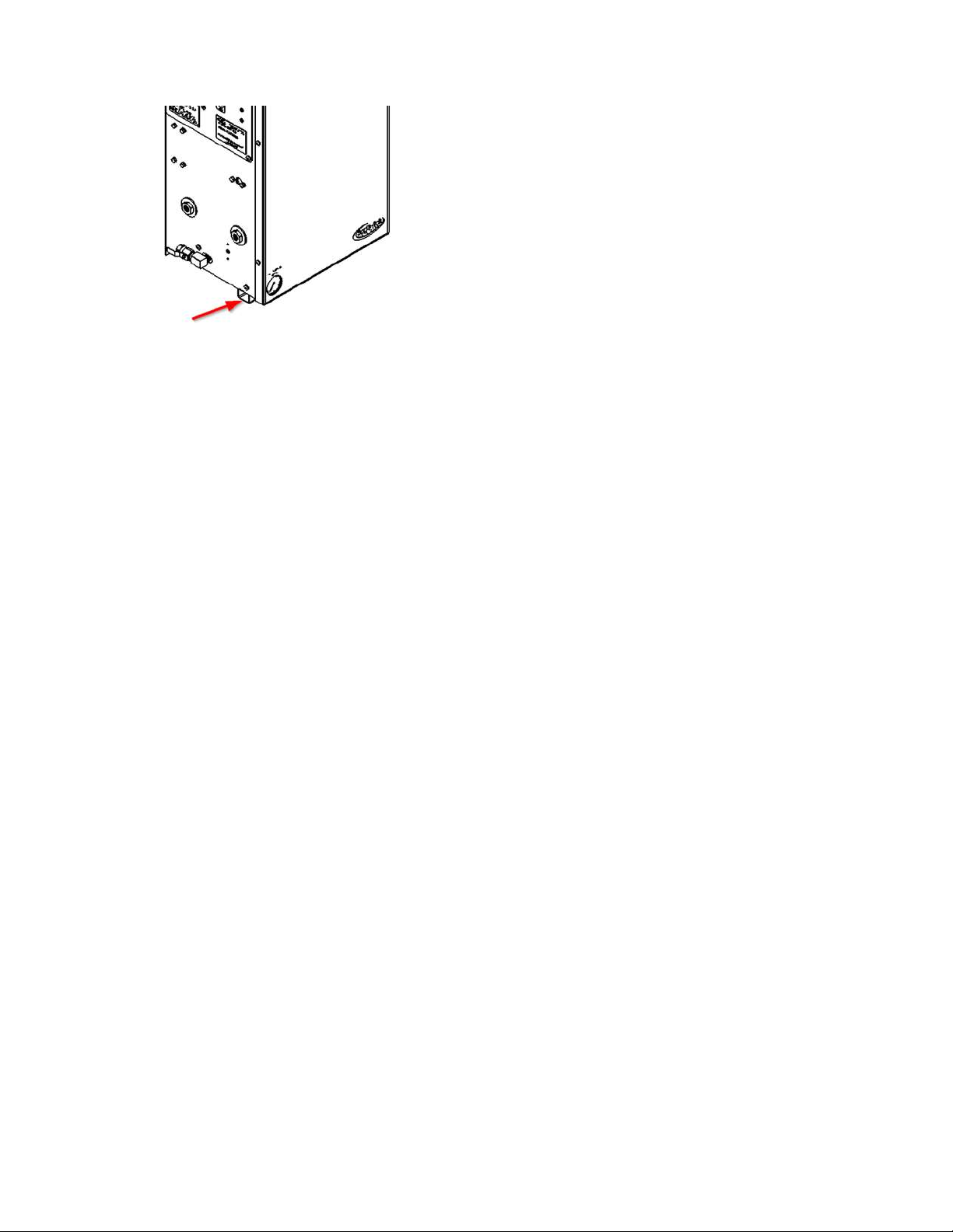
connections, and the front cover. There is a ¼” OD tube drain port on the bottom right of the cabinet. This can be
plumbed to the nearest site drain.
There is an optional mounting bracket kit (STS Part #: A05-TYP1-WH), that allows you to mount the system on a
standard 16” wall stud width. Otherwise, use the mounting holes on the cabinet for mounting the BrewBlast™
70CPH securely and level, directly to the wall.

BrewBlast™ 70CPH O&M South-Tek Systems
9
Optional Mounting Bracket Kit Procedures
1. All BrewBlast™ BrewBlast™ 70CPH mounting holes and optional mounting bracket holes are for ¼”
screws/anchors.
2. All brackets must be installed in orientation as shown to work correctly.
3. Install the cabinet-mounting brackets on the BrewBlast™ BrewBlast™ 70CPH first with the provided
bolts/lock nuts.
4. Locate the wall-mounting bracket. It is an 18” bracket without the rectangular cutouts and will need to
be installed on the wall at the desired height and level. The bracket has 16” center to center holes so
the unit can be mounted directly to studs. This bracket will need to be mounted per the diagram below
using the appropriate hardware for your type of wall material (wood, sheet metal, masonry, etc.). The
12” bracket that is fastened to the top flange of the cabinet can be hung from the 18” bracket once the
18” bracket has been mounted to the wall. Reference the diagram below to see how the angles are to
be oriented on the back of the cabinet in comparison to the wall.
a. Use the supplied nuts and bolts to attach the upper 12” bracket onto the top flange per the
diagram.
b. Use the supplied carriage bolts and nuts to attach the 18” lower bracket to the bottom flange,
but do not overtighten the nuts yet. After installing the system, you may want to offset the
bracket slightly, hence the rectangular slots.
5. Optional: If wall studs are not 16” center to center or you have the need to reinforce the mounting
area, a ½” or thicker plywood is recommended to be installed prior to hanging the system. Use best
general practices to ensure that the wood and system will be secure at its full weight and remember
that it will be vibrating from the compressor running.
6. Once the mounting brackets are all in place, hang the BrewBlast™ BrewBlast™ 70CPH cabinet from
the top bracket making sure it is centered.
a. The cabinet should have at least 4” on either side for breathing/cooling purposes.
b. Do not install near heat source or where steam or water is present. Damage to system or
bodily harm may result as well as voiding warranty.
Warning: Secure the BrewBlast™ BrewBlast™ 70CPH to the wall at the top and bottom flanges. Failure to do so
could cause damage or bodily injury.

BrewBlast™ 70CPH O&M South-Tek Systems
10
4.4 INSTALLATION (BREWBLAST™ 70CPH
The BrewBlast™ BrewBlast™ 70CPH is a turnkey system that can be mounted to the wall and connected to the
source. If the blender is included, the end user will have to connect the CO2to the BrewBlast™ BrewBlast™
70CPH. Use caution when working with pressurized gas, making sure that all fittings and gas lines are installed
correctly. Always leak check every line before using the system.
Note: Line leaks will cause the BrewBlast™ BrewBlast™ 70CPH to run excessively, shortening its life.
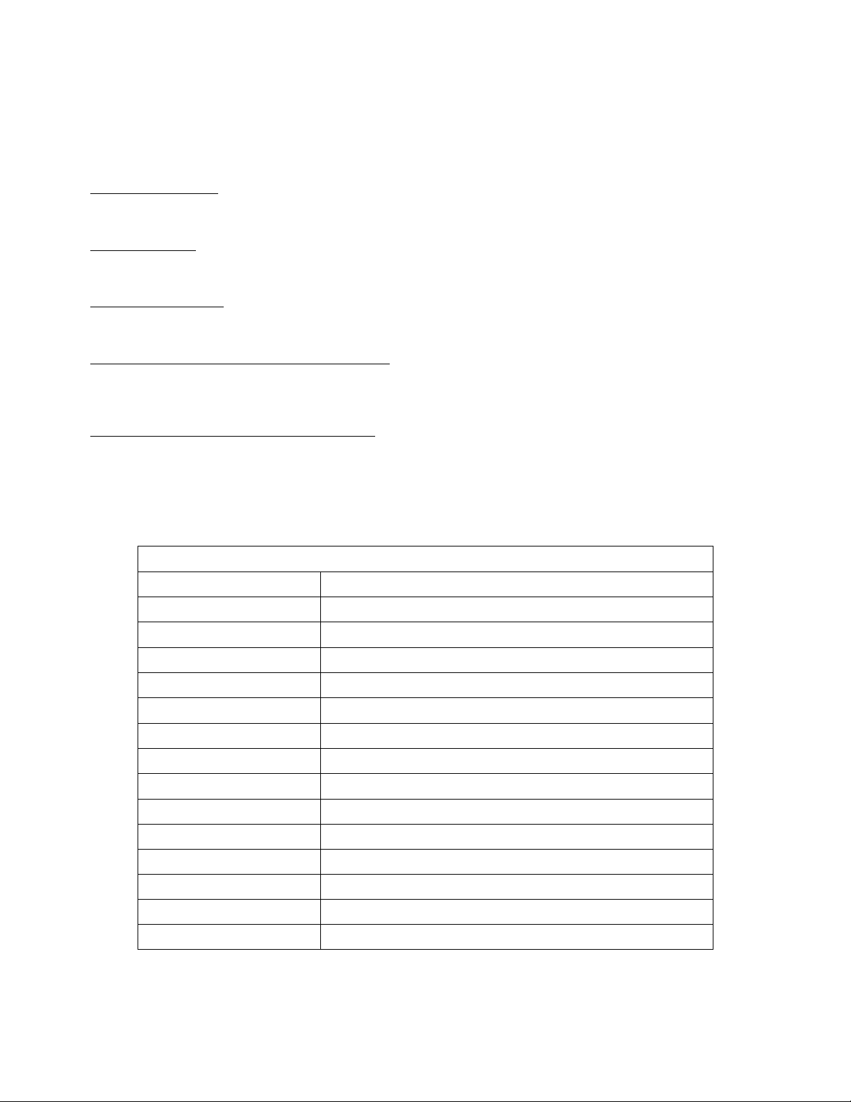
The BrewBlast™ BrewBlast™ 70CPH is provided standard supplying 100% nitrogen, but a gas blend (of N2and
CO2) can be added as an option. These lines can be split individually to provide the correct gas and/or blended gas
to all of the beverage lines. Use only quality beverage tubing and fittings for all connections. Keep in mind the
temperature and pressure requirements when selecting them.
Always install a valve (on/off) on each individual line. This will help with troubleshooting the system. Never detach a
line with pressure on it before closing the valve; this could cause damage to the equipment or bodily injury. Also
avoid depressurizing the keg at all costs; this will negatively affect the coffee quality. Always shut off the valve and
remove the tap from the keg before changing or servicing the gas lines.
Item
#
STS Part #
Description
Qty
1
BB™
BrewBlast™
70CPH
BrewBlast BrewBlast™ 70CPH Nitrogen
Generator
1
2
800-133
S-100/200 12" Mounting Bracket
1
3
800-134-B
S-100/200/400 18" Mounting Bracket
1
4
800-129
Type 1 Lower Wall Mount Bracket
1
5
Misc
0.250" -20 x 0.750" Carriage Bolt
2
6
Misc
0.250" -20 x 0.750" Hex Cap Screw
2
7
Misc
0.250" Nylock Nut
4
8
Misc
0.250" Flat Washer
2
BrewBlast™ 70CPH O&M South-Tek Systems
11
Two condensate drains for the generator are located on the bottom right of the cabinet. It is the responsibility of the
installer to plumb these drains to an area where standing water is trapped or a drain is located. Failure to do so can
cause a slipping hazard on the floor below the generator.
If your system requirements are more involved, please consult your sales representative or equipment installer for
help.

BrewBlast™ 70CPH O&M South-Tek Systems
12

BrewBlast™ 70CPH O&M South-Tek Systems
13
Optional Separate N2 Storage Tank Setup
BrewBlast™ 70CPH O&M South-Tek Systems
14
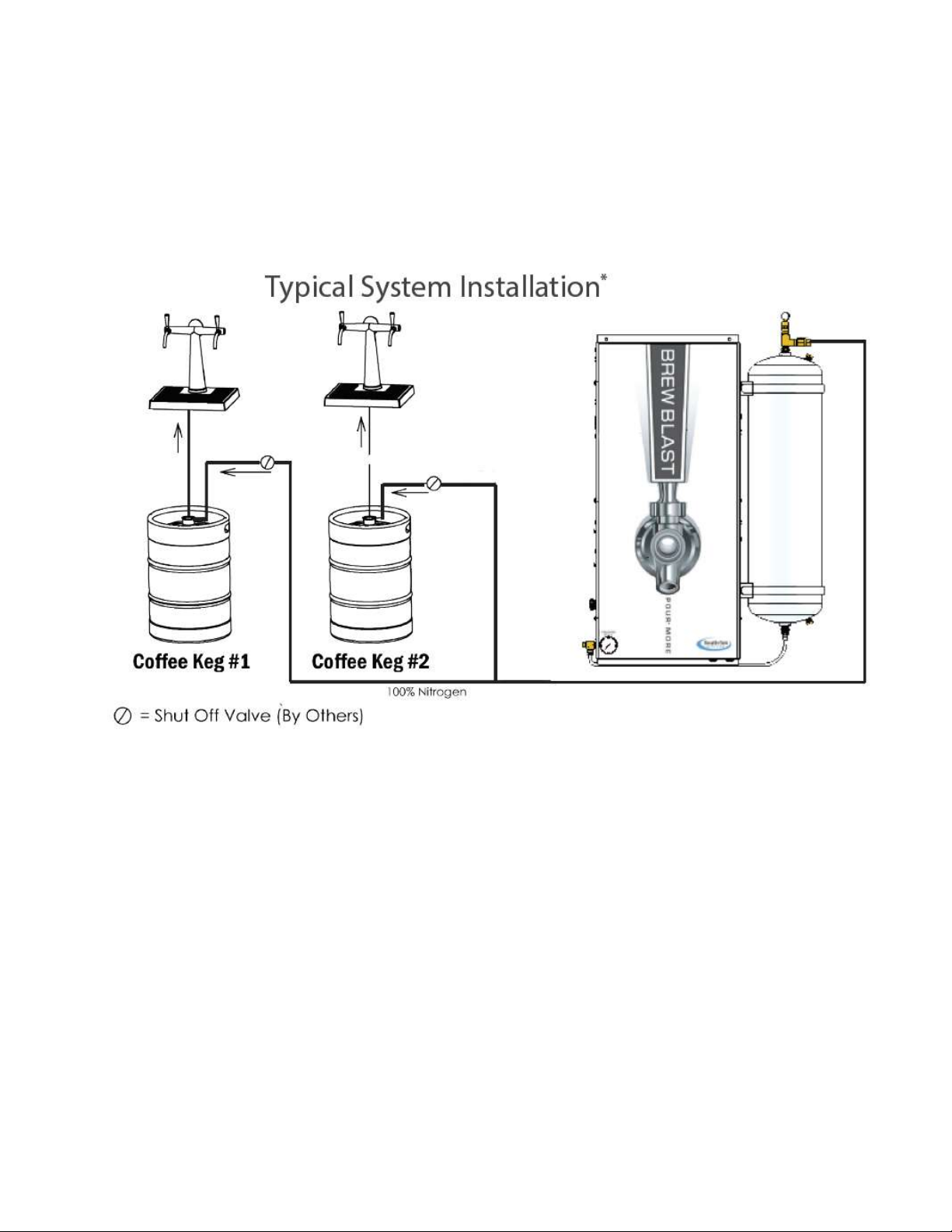
4.5 NITROGEN CYLINDER BACK-UP (BREWBLAST™ 70CPH)
It is recommended that a backup system be installed in case of any unforeseen complications. A backup N2
Cylinder tank can be used instead of the generated nitrogen from the BrewBlast™ 70CPH. If the optional gas
blender is present, it will allow the nitrogen to go through the blender to achieve the desired results. To install the
back-up tank, you will need a cylinder with valve and regulator (regulated to 85 psig). Install the N2back-up on the
gas line on Port 4 of the BrewBlast™ 70CPH as follows:
1. The N2back-up cylinder should have a high pressure regulator and ball valve on the output. It is
recommended to have a lockable ball valve and/or labeled for “Backup use only”.
2. If the Back-up system is turned on, the backup will fill the N2Storage tank and flow to the BrewBlast™
70CPH keeping the internal blender pressurized with Nitrogen.
See below for visual piping connections:
4.6 START-UP PROCEDURES (BREWBLAST™ 70CPH)
It is necessary to use caution when working with pressurized gas, making sure that all fittings and gas
lines are
installed correctly. Always leak check every line before using the system.
Note: Line leaks will cause the BrewBlast™ BrewBlast™ 70CPH to run excessively, shortening its life and
placing excess wear on the compressor.
The installation layout drawings are provided with your system in the documentation package. For electronic
copies, please contact your local distributor. Review and make sure the equipment is installed and configured per
the installation layout drawings. Ensure that you follow the correction installation drawing per your system’s design.
In some cases, a N2Bypass system for pre-filling is required in the installations to meet code.

BrewBlast™ 70CPH O&M South-Tek Systems
15
If your system requirements are more complex, please consult your sales representative or equipment
installer for
more detailed installation instructions.
1. The BrewBlast™ BrewBlast™ 70CPH is supplied with ½” NPT female inlet and outlet fittings. Make sure to use
Teflon tape or similar on all fittings so they do not leak.
2. Connect the BrewBlast™BrewBlast™ 70CPH to the storage tank and then to the coffee system.
3. Once connections are made, slowly open the system’s On/Off Valve.
A. You will hear air rushing through the system and N2 filling the BrewBlast™ BrewBlast™ 70CPH
storage tank.
B. If you hear a leak or have a bad connection, shut the valve off and make the correction.
C. If there is a leak within the unit, remove the cover and locate the issue. If you have to replace any
parts, use only factory parts supplied from your distributor or South-Tek
Systems. Consult the
manufacturer if there are any questions.
4. Once the BrewBlast™ BrewBlast™ 70CPH fills the storage tank to 85 PSIG, the system will enter standby –the
system’s green N2 Production light will change to orange indicating that the system is in standby. This will shut
the air flow off through the generator and eventually shut off the air compressor once it reaches the air
tank cutout pressure.
A. This will prolong the life of your compressor’s motor.
B. This also prolongs the life of the nitrogen generator’s media and filter.
i. Lesser quality systems have a constant purge flow through their systems which decreases
system life and increases the need for maintenance.
5. When you draw N2 off the system and the tank pressure falls below cut-in pressure
(approximately 62
PSIG), the pressure switch will trigger the system back into run mode and start
recharging the storage tank
automatically. The pressure switch is preset at the factory –no field adjustment is required.
4.7 CHECKING FOR LEAKS
When a leak is suspected, first try to listen for leaks around the connection ports. If a leak is found, isolate the area
so that there is no pressure on it. Fix the leaking part and return the system back to operation. If no leak can be
heard, turn off the unit and try isolating sections to see if there is a pressure loss. If the BlastOff™ option is included
with your unit, the system will alarm indicating that there is a leak in the line. Consult with your installer if you
cannot locate the leakage area.
To determine if the leak is within the cabinet:
A. With the unit powered on, close off all output gas. If no ball valve is installed on the output ports, it is
recommended to remove the gas lines and install a plug.
B. Allow the system to continue running. Within 1 hour, the system should reach the “Standby” mode.
C. Wait for 5 minutes and if the system remains in the “standby” mode, then the leak is after this point.
Check the gas lines exterior to the cabinet all the way back to the keg system.
D. If the unit goes back into “run” mode, the leak is within the cabinet. Check all the lines going to the
blender and back to the tank.
To find the leak within the cabinet:
1. Open the front cabinet door and locate the N2storage tank.
2. Close off the output ball valve from the tank (upper ball valve on the red manifold).
3. Watch the exterior gauge above the cabinet for 60 seconds. If you see the pressure dropping, the
leak is somewhere between the output ports, to the blender (if one is present), and back to the closed
off ball valve on the tank. Fill and/or listen for leaks and fix them once found. If the pressure is not
dropping, go to the next step.
4. With the unit still running, close off the input ball valve to the tank (lower ball valve on the red
manifold).
5. Within 5 minutes, the system should go into “Standby” Mode. If it doesn’t, contact your local
provider/installer for further assistance.

BrewBlast™ 70CPH O&M South-Tek Systems
16
6. Once in “Standby” mode, wait 60 seconds. After 60 seconds, the system should remain in “standby”
mode. If it doesn’t, the leak is somewhere between the check valve and the output ball valve on the
tank.
7. If the system remains in standby, contact your local distributor/installer for further assistance.
4.8 ACCESS CONTROLS
The built-in control timer is programmed to function without requiring the user to input any values. Do not attempt to
modify the timing or the warranty will be voided. In case of a failure, first attempt to cycle the power to the system. If
that does not work, please contact your provider for further instructions.
4.9 STARTING THE SYSTEM
To start the system, turn on the power switch and make sure any valves to the gas lines are in the open position.
4.10 STOPPING THE SYSTEM
To stop the system, close off any valves on the gas lines. Powering down the system is not necessary. If
emergency shut off is required, turn off the power switch on the side on the control panel.
5SYSTEM USAGE
5.1 INSTRUCTIONS
The BrewBlast™ 70CPH is intended to be used to generate nitrogen to push coffee out of the keg. Follow the
installation instructions above and only use in an approved environment. The generator generates enough nitrogen
to push 40 pints per hour. Make sure that proper regulators, cooler temperature, and line temperatures are
maintained, otherwise you will not be able to effectively push coffee from the keg. Please consult with your local
distributor for questions not answered in this manual.
The system is designed for 24 hour operation, but routine maintenance on the filters must be performed. Reference
the “System Maintenance” section for detailed maintenance instructions.
5.2 ALARM NOTIFICATION
BlastOff™ - Leak Detection System Alarm
All BrewBlast™ 70CPH models come standard with the patented BlastOff™ - Leak Detection System. It detects
line leaks within the downstream gas lines from the N2Generator to the kegs. Line leaks could be due to a keg
not being tapped correctly, a coffee gas line leak or fitting therein failing, etc. These leaks are potential safety
hazards, can cause the CO2to deplete quickly, and could cause your BrewBlast™ 70CPH to run in excess
(decreasing the life of the unit).
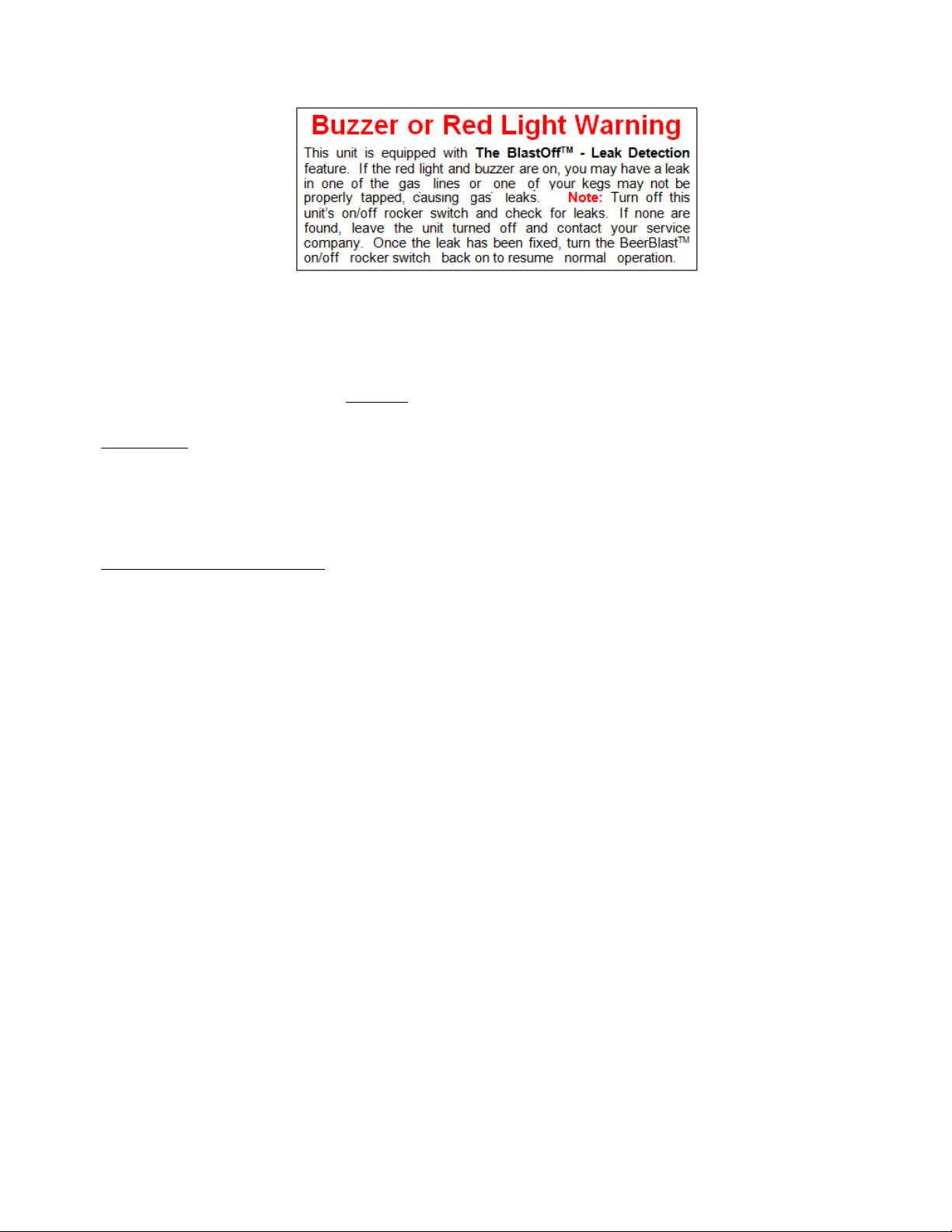
Once a leak has been detected, the BlastOff™ is set to initiate a buzzer, displays “B.Off” in red on the controller
screen, and shuts off the BrewBlast™ 70CPH until the problem has been remedied. To reset the BlastOff™,
simply turn off the BrewBlast™ 70CPH and turn it back on. The BrewBlast™ 70CPH can be ordered with the
BlastOff™ System Factory installed or the system can be retrofitted in the field. Some rewiring is required to
field install.
Never reset repeatedly; if the BlastOff™ goes off daily, there is a real potential issue. Consult your installer for a
solution. The label below will be on your BrewBlast™BrewBlast™ 70CPH if factory installed.
BrewBlast™ 70CPH O&M South-Tek Systems
17
6SYSTEM MAINTENANCE
When performing maintenance on the BrewBlast™ BrewBlast™ 70CPH, make sure to power down the system.
Remove the front cover to gain access to the filters.
Annual Filter replacement kit part # FRP-001
Air Pre-Filter
The integrated Air Compressor has an air intake pre-filter. It is designed to prevent particles from entering into the
compressor housing and damaging internal components. This filter needs to be replaced once per year or every
1,000 hours, whichever comes first. To do so, remove the pre-compressor filter cap by twisting it clockwise.
Remove the old element and use a clean dry cloth to clean the filter bowl before installing the new element.
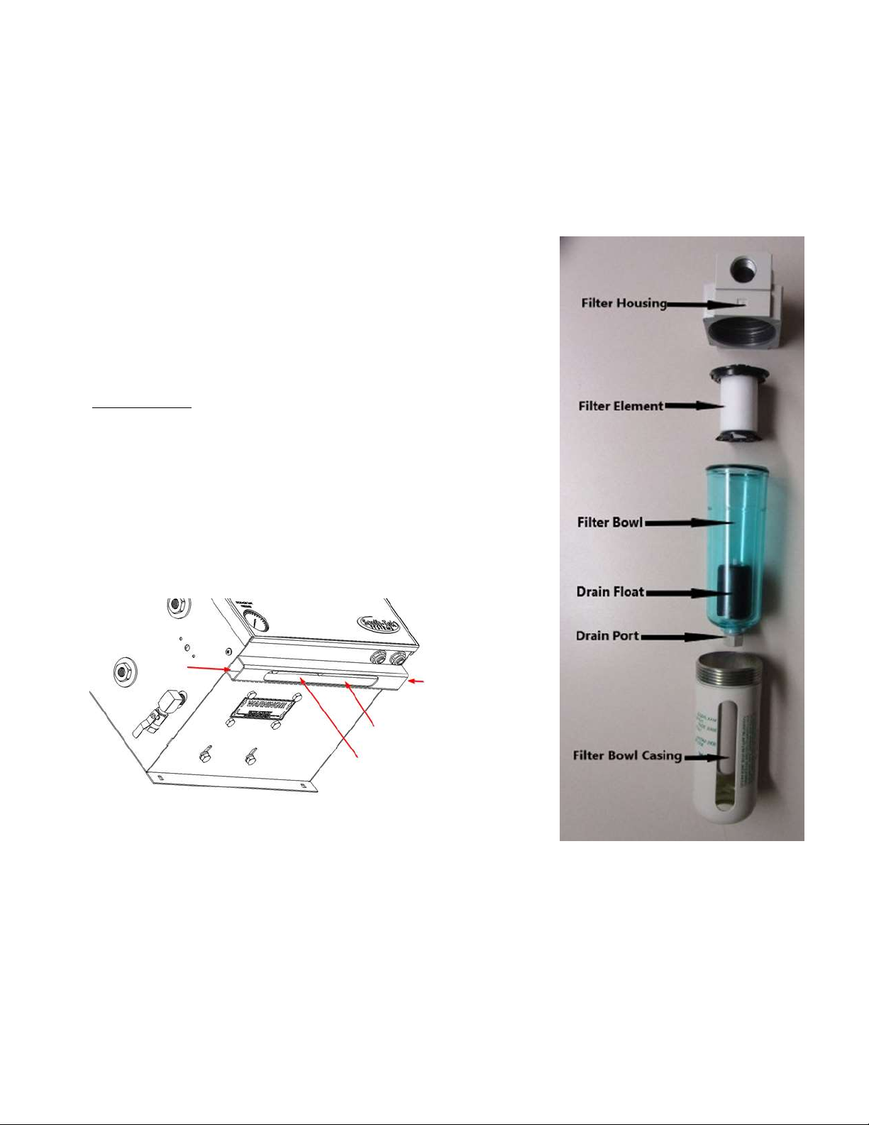
Particulate and Coalescing Filter
The particulate and coalescing filter after the air compressor is designed to capture particulate and moisture prior to
entering the rest of the system. These filters and seals need to be replaced once per year or every 1,000 hours,
whichever comes first. To do so,
WARNING: Do not try to remove filter bowls until the filter is completely depressurized.
1. Disconnect the clear-blue drain tubes from the bottom of the bowls.
2. To remove the bowl, turn the metal casing around the blue plastic filter bowl counter-clockwise until it
unscrews completely from the filter housing. Then twist slightly and pull the blue plastic bowl downwards
out of the housing.
3. Inspect the bowls. If the drain system is working properly, the bowls should not be full of water.
4. Remove the particulate filter element by pulling the black plastic filter element holder out of the filter bowl
and, carefully, twisting the top and bottom piece counter-clockwise until the holder pulls apart. Take notice
of how the element looks. If the element is excessively dirty, more frequent filter changes are
recommended.
5. The coalescing element can be removed by turning it counter-clockwise by hand; then replace with the new
element in the reverse order.
NOTE: A plugged drain system will cause water and oil to carry over into the system, which will cause permanent
damage to the media inside the unit. Such damage is not covered by the manufacturer's warranty. Use of filters
other than those specified by South-Tek Systems could result in damages not covered by the warranty.
BrewBlast™ 70CPH O&M South-Tek Systems
18
6. Wash the bowls in soapy water and rinse thoroughly as needed. Use of light air gun to remove debris is
also acceptable. Make sure to always wipe down with a clean and dry cloth.
7. Install new filter element and replace O-rings as needed.
8. Put the filter bowls back on the system in reverse order of how it was removed making sure the bowl is
seated in place correctly. Only tighten metal casing around filter bowl hand tight.
9. Be sure to utilize the filter replacement schedule on the face of
the filter bracket to keep track of when the filter was replaced
last.
10. Put the front cover back on the cabinet and the unit can be
powered up again. Once powered up, you should hear the air
compressor turn on and the BrewBlast™ 70CPH will resume
producing nitrogen.
Proper cleaning
In beverage, restaurant and pub applications this product is certified as
an NSF product. To ensure compliance with typical requirements of
these environments the product should be cleaned with mild detergent.
Specific to BrewBlast™ BrewBlast™ 70CPH models ensure that the
lower support channel is clean. Clean with approved kitchen cleaner,
apply a rag or brush through the openings as shown with arrows. Keep
free from foreign objects, dust, debris and vermin.
BrewBlast™ 70CPH O&M South-Tek Systems
19

BrewBlast™ 70CPH O&M South-Tek Systems
20
7KEY CONTACTS
Contact your local provider/installer with any questions regarding the performance and/or maintenance of the
system. They will be best suited to answer your questions and should be readily available to help provide a
resolution to any issues you may have.
8FAQS
8.1 POWER ISSUES
If the BrewBlast™ 70CPH does not have power, the production and storage of nitrogen will become apparent once
the storage pressure drops. The taps will begin to pour slowly or not at all.
1. Check the power cord
2. Has the building’s circuit breaker or GFCI tripped? Locate the breaker and reset. If the breaker
continues to trip, the circuit may be overloaded.
8.2 PRESSURE ISSUES
If the gas blender is included, both gases (N2and CO2) will need available pressures over 40 psig. Blenders will
shut down output if either gas is not present over 40 psig.
The BrewBlast™ 70CPH will produce and store nitrogen between 60-85 psig. Once the storage tank reaches 85
psig, the system will go into Stand-By Mode. When the pressure drops to 60 psig, the system should go into
Operation Mode and begin to refill the storage tank. If you are out of the specifications, we need to determine
where the issue is. Contact the manufacturer or a factory trained technician.
CO2 Pressure Check:
If you have the blender option, check the CO2regulator pressure gauge. It should read between 80 and 100 psig. If
it is lower, check the CO2Storage tank to see if it needs refilling or if the pressure regulator needs adjustment. The
pressure going into the BrewBlast™ 70CPH is recommended to be set at 85 psig.
Nitrogen Pressure Check:
Look at the pressure gauge on the top of the cabinet. It should be between 50 and 85 psig. If the pressure is low, a
couple things need to be checked:
Check the power.
Check for leaks throughout the system. Refer to section on Checking for Leaks.
Pressure Regulation Check:
If the CO2and N2are both present and the blender is outputting gas, it is possible that a regulator is malfunctioning
or needs adjustment. The mixed gas coming from the blender should be between 40-85 psig (dependent on the N2
and CO2pressures going into the blender). A primary regulator is usually installed on the output lines coming from
the BrewBlast™ 70CPH. The primary regulator is there to “step down” the available pressure to the kegs. There are
typically secondary regulators located further downstream on the mixed gas lines going to the kegs. The secondary
regulators are there to individually tune each keg. Some coffees require more/less pressure and regulating each
keg individually will allow the coffee pouring to be optimized.
If the BrewBlast™ 70CPH is operating correctly, then the establishment should contact their Draft Coffee System
Technician to adjust the regulators for optimal performance.
This manual suits for next models
1
Table of contents


