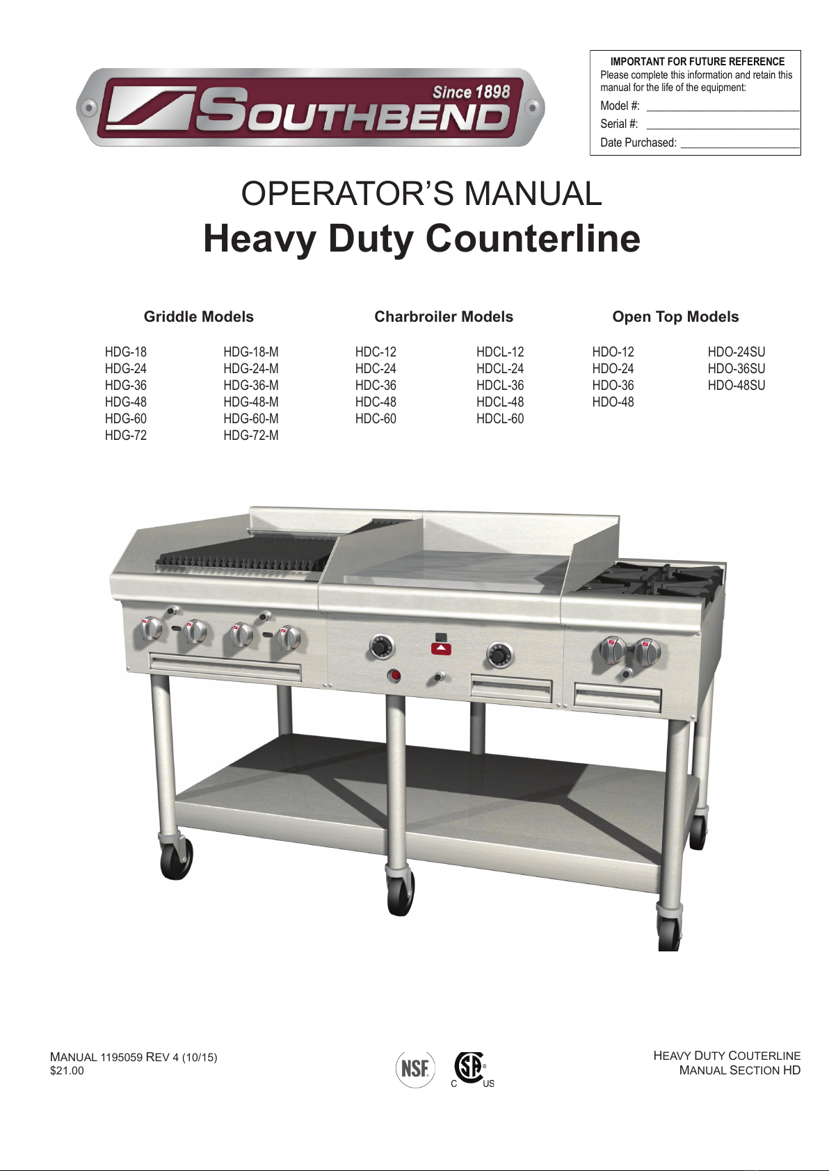
Southbend HDG-18 User manual
MANUAL 1195059 REV 4 (10/15)
$21.00
HEAVY DUTY COUTERLINE
MANUAL SECTION HD
IMPORTANT FOR FUTURE REFERENCE
Please complete this information and retain this
manual for the life of the equipment:
Model #:
___________________________
Serial #:
___________________________
Date Purchased:
_____________________
HDG-18-M
HDG-24-M
HDG-36-M
HDG-48-M
HDG-60-M
HDG-72-M
OPERATOR’S MANUAL
Heavy Duty Counterline
HDG-18
HDG-24
HDG-36
HDG-48
HDG-60
HDG-72
Griddle Models
HDCL-12
HDCL-24
HDCL-36
HDCL-48
HDCL-60
HDC-12
HDC-24
HDC-36
HDC-48
HDC-60
HDO-24SU
HDO-36SU
HDO-48SU
HDO-12
HDO-24
HDO-36
HDO-48
Charbroiler Models Open Top Models
Total Restaurant Supply - https://totalsupply1.com - Toll Free 1-800-944-9304 - Local 507-288-9454
2940 Hwy 14 W, Rochester, MN 55901
HEAVY DUTY COUTERLINE
OPERATOR’S MANUAL 1195059 REV 4 (10/15)
PAGE 2 OF 28
1100 Old Honeycutt Road Fuquay-Varina, North Carolina 27526 USA
www.southbendnc.com
WARNING
Improper installation, adjustment, alteration, service or maintenance can cause property damage, injury
or death. Read the installation, operating and maintenance instructions thoroughly before installing or
servicing this equipment.
SAFETY PRECAUTIONS
Before installing and operating this equipment, be sure everyone involved in its operation is fully trained and aware of
precautions. Accidents and problems can be caused by failure to follow fundamental rules and precautions.
The following symbols, found throughout this manual, alert you to potentially dangerous conditions to the operator,
service personnel, or to the equipment.
CAUTION
WARNING
NOTICE
This symbol warns of immediate hazards that will result in severe injury or death.
This symbol refers to a potential hazard or unsafe practice that could result in injury or death.
This symbol refers to a potential hazard or unsafe practice that could result in injury, product
damage, or property damage.
This symbol refers to information that needs special attention or must be fully
understood, even though not dangerous.
DANGER
WARNING
FIRE HAZARD
FOR YOUR SAFETY
Do not store or use gasoline or other ammable vapors and liquids in the vicinity of this or any other appliance.
Keep area around cooking appliances free and clear of combustibles.
Purchaser of equipment must post in a prominent location detailed instructions to be followed in the event the
operator smells gas. Obtain the instructions from the local gas supplier.
WARNING
Asphyxiation can result from improper ventilation. Do not obstruct the ow of combustion and ventilation air to and
from your cooking equipment.
NOTICE
Be sure this Operator’s Manual and important papers are given to the proper authority to retain for future reference.
NOTICE
This product is intended for commercial use only. NOT FOR HOUSEHOLD USE.
Copyright © 2014 by Southbend. All rights reserved. Published in the United States of America.
Total Restaurant Supply - https://totalsupply1.com - Toll Free 1-800-944-9304 - Local 507-288-9454
2940 Hwy 14 W, Rochester, MN 55901

HEAVY DUTY COUTERLINE
OPERATOR’S MANUAL 1195059 REV 4 (10/15) PAGE 3 OF 28
Congratulations! You have purchased one of the nest pieces of heavy-duty commercial cooking equipment on the
market.
You will nd that your new equipment, like all Southbend equipment, has been designed and manufactured to meet
the toughest standards in the industry. Each piece of Southbend equipment is carefully engineered and designs are
veried through laboratory tests and eld installations. With proper care and eld maintenance, you will experience
years of reliable, trouble-free operation. For best results, read this manual carefully.
RETAIN THIS MANUAL FOR FUTURE REFERENCE.
Table of Contents
Specications .........................................................................................................................................4
Installation ..............................................................................................................................................6
Operation ...............................................................................................................................................13
Cleaning ................................................................................................................................................18
Adjustments ..........................................................................................................................................20
Troubleshooting .....................................................................................................................................24
Read these instructions carefully before attempting installation. Installation and initial startup should be performed
by a qualied installer. Unless the installation instructions for this product are followed by a qualied service
technician (a person experienced in and knowledgeable with the installation of commercial gas an/or electric cooking
equipment) then the terms and conditions on the Manufacturer’s Limited Warranty will be rendered void and no
warranty of any kind shall apply.
In the event you have questions concerning the installation, use, care, or service of the product, contact:
Southbend Technical Service
1100 Old Honeycutt Road
Fuquay Varina, North Carolina 27526 USA
www.southbendnc.com
The serial plate is located on the interior side of the lower front panel, as shown below.
TABLE OF CONTENTS
Griddle Models Charbroiler Models Open Top Models
Serial plate is located on the rear of each unit above the gas inlet pipe.
The serial number is also located on the front of the unit on the Warranty
Service label (see example at right).
Figure 1
Total Restaurant Supply - https://totalsupply1.com - Toll Free 1-800-944-9304 - Local 507-288-9454
2940 Hwy 14 W, Rochester, MN 55901
HEAVY DUTY COUTERLINE
OPERATOR’S MANUAL 1195059 REV 4 (10/15)
PAGE 4 OF 28
SPECIFICATIONS
NOTICE
Installation must comply with National Fuel Gas Code, ANSI Z223.1, Natural Gas Installation Code, CAN/
CGA-B149.1, or the Propane Installation Code, CAN/CGA-B149.2, as applicable.
Local codes regarding installation vary greatly from one area to another. The National Fire Protection Association, Inc.
states in its NFPA 96 latest edition that local codes are the “authority having jurisdiction” when it comes to installation
requirements for equipment. Therefore, installations should comply with all local codes.
Southbend reserves the right to change specications and product design without notice. Such revisions do not entitle
the buyer to corresponding changes, additions, or replacements for previously purchased equipment.
This product is intended for commercial use only, not for household use.
This product is intended for commercial use only, not for household use.
GAS SUPPLY
The serial plate is located on the interior side of the valve panel (see Figure 1 on page 3). It indicates the type of gas the
unit is equipped to burn. All Southbend equipment is adjusted at the factory. Check type of gas on serial plate.
These models are design-certied for operation on natural or propane gases. The unit is shipped congured for the type
of gas specied by the purchaser. A kit for conversion to a different type of gas may be purchased from Southbend (see
page 21 for conversion instructions).
This appliance should be connected ONLY to the type of gas for which it is congured.
An adequate gas supply is imperative. Undersized or low pressure lines will restrict the volume of gas required for satis-
factory performance.. A 1/8” pressure tap is located on the manifold to measure the manifold pressure.
An adequate gas supply line to the unit should be no smaller than the inside diameter of the pipe from the unit to which
it is connected.
Purge the supply line to clean out dust, dirt, or other foreign matter before connecting the line to the unit.
All pipe joints and connections must be tested thoroughly for gas leaks. Use only soapy water for testing on all gases.
NEVER use an open ame to check for gas leaks. All connections must be checked for leaks after the unit has been put
into operation. Test pressure should not exceed 14” W.C.
SPECIFICATIONS
CAUTION
THIS APPLIANCE MUST BE DISCONNECTED FROM THE GAS SUPPLY PIPING SYSTEM DURING ANY
PRESSURE TESTING OF THAT SYSTEM AT TEST PRESSURES IN EXCESS OF 1/2 PSIG (3.45 kPa).
THIS APPLIANCE MUST BE ISOLATED FROM THE GAS SUPPLY PIPING SYSTEM DURING ANY PRESSURE
TESTING OF THE GAS SUPPLY PIPING SYSTEM AT TEST PRESSURES EQUAL TO OR LESS THAN 1/2 PSIG
(3.45 kPa).
Total Restaurant Supply - https://totalsupply1.com - Toll Free 1-800-944-9304 - Local 507-288-9454
2940 Hwy 14 W, Rochester, MN 55901
HEAVY DUTY COUTERLINE
OPERATOR’S MANUAL 1195059 REV 4 (10/15) PAGE 5 OF 28
CLEARANCES
SPECIFICATIONS
WARNING
There must be adequate clearance between units and adjacent construction. Clearance must also be provided for
servicing and for operation. Measure back clearance from rear of 2” stand-off brackets.
Griddle Models Open Top Models
Sides 12” 10”
Back 8” 7”
Minimum Clearances from COMBUSTABLE construction:
Griddle Models Charbroiler Models Open Top Models
Sides 0” 0” 0”
Back 0” 0” 0”
Minimum Clearances from NON-COMBUSTABLE construction:
WARNING
Improper ventilation can result in personal injury or death. Ventilation which fails to properly remove ue products can
cause headaches, drowsiness, nausea, or could result in death.
All units must be installed in such a manner that the ow of combustion and ventilation air are not obstructed.
Provisions for adequate air supply must be provided. Do not obstruct the front or rear of the unit as combustion air
enters through these areas.
VENTILATION
NOTICE
Proper ventilation is the owner’s responsibility. Any problem due to improper ventilation will not be covered by the
warranty.
Air for combustion enters the rear of the appliance. An exhaust ue runs along the top rear edge of griddle and charbroiler
models.
Southbend recommends that a ventilation canopy extend 6” past the edges of the appliance and be located 6’6” above
the oor.
If a wall exhaust fan is installed in the wall behind the appliance, it should be at least two feet above the top of the
appliance.
To avoid a negative pressure condition, return air must be brought into the room to replenish the air being removed by the
ventilation exhaust fan. RETURN-AIR FANS MUST NOT BLOW DOWN ONTO THE APPLIANCE.
Ventilation lters should be installed at an angle of 45° or more from the horizontal. This prevents dripping grease and
facilitates collecting the run-off grease in a drip pan, usually installed with a lter.
Be sure to inspect and clean the ventilation system according to the ventilation equipment manufacturer’s instructions.
In case of unsatisfactory performance on any appliance, check the appliance with the ventilation exhaust fan in the “OFF”
position. Do this only long enough to check equipment performance. Then turn the fan back on and let it run to remove
any exhaust that may have accumulated during the test.
Total Restaurant Supply - https://totalsupply1.com - Toll Free 1-800-944-9304 - Local 507-288-9454
2940 Hwy 14 W, Rochester, MN 55901

HEAVY DUTY COUTERLINE
OPERATOR’S MANUAL 1195059 REV 4 (10/15)
PAGE 6 OF 28
NOTICE
Installation must comply with National Fuel Gas Code, ANSI Z223.1, Natural Gas Installation Code, CAN/
CGA-B149.1, or the Propane Installation Code, CAN/CGA-B149.2, as applicable.
These installation procedures must be followed by qualied personnel or warranty will be void.
Local codes regarding installation vary greatly from one area to another. The National Fire Protection Association, Inc.
states in its NFPA 96 latest edition that local codes are the “authority having jurisdiction” when it comes to installation
requirements for equipment. Therefore, installations should comply with all local codes.
IMMEDIATELY INSPECT FOR SHIPPING DAMAGE
All containers should be examined for damage before and during unloading. The freight carrier has assumed
responsibility for its safe transit and delivery. If damaged equipment is received, either apparent or concealed, a claim
must be made with the delivering carrier.
Apparent damage or loss must be noted on the freight bill at the time of delivery. The freight bill must then be signed
by the carrier representative (Driver). If the bill is not signed, the carrier may refuse the claim. The carrier can supply
the necessary forms.
A request for inspection must be made to the carrier within 15 days if there is concealed damage or loss that is not
apparent until after the equipment is uncrated. The carrier should arrange an inspection. Be certain to hold all contents
plus all packing material.
1. Uncrate carefully. Report any hidden damage to the freight carrier IMMEDIATELY.
2. Do not remove any tags or labels until unit is installed and working properly.
Step 1: Unpacking
INSTALLATION
INSTALLATION
Step 2: Attach Countertop Legs
The appliance can be mounted in several ways:
Mount it on short, countertop legs.
Mount it on a stand that rests on the oor.
Total Restaurant Supply - https://totalsupply1.com - Toll Free 1-800-944-9304 - Local 507-288-9454
2940 Hwy 14 W, Rochester, MN 55901
HEAVY DUTY COUTERLINE
OPERATOR’S MANUAL 1195059 REV 4 (10/15) PAGE 7 OF 28
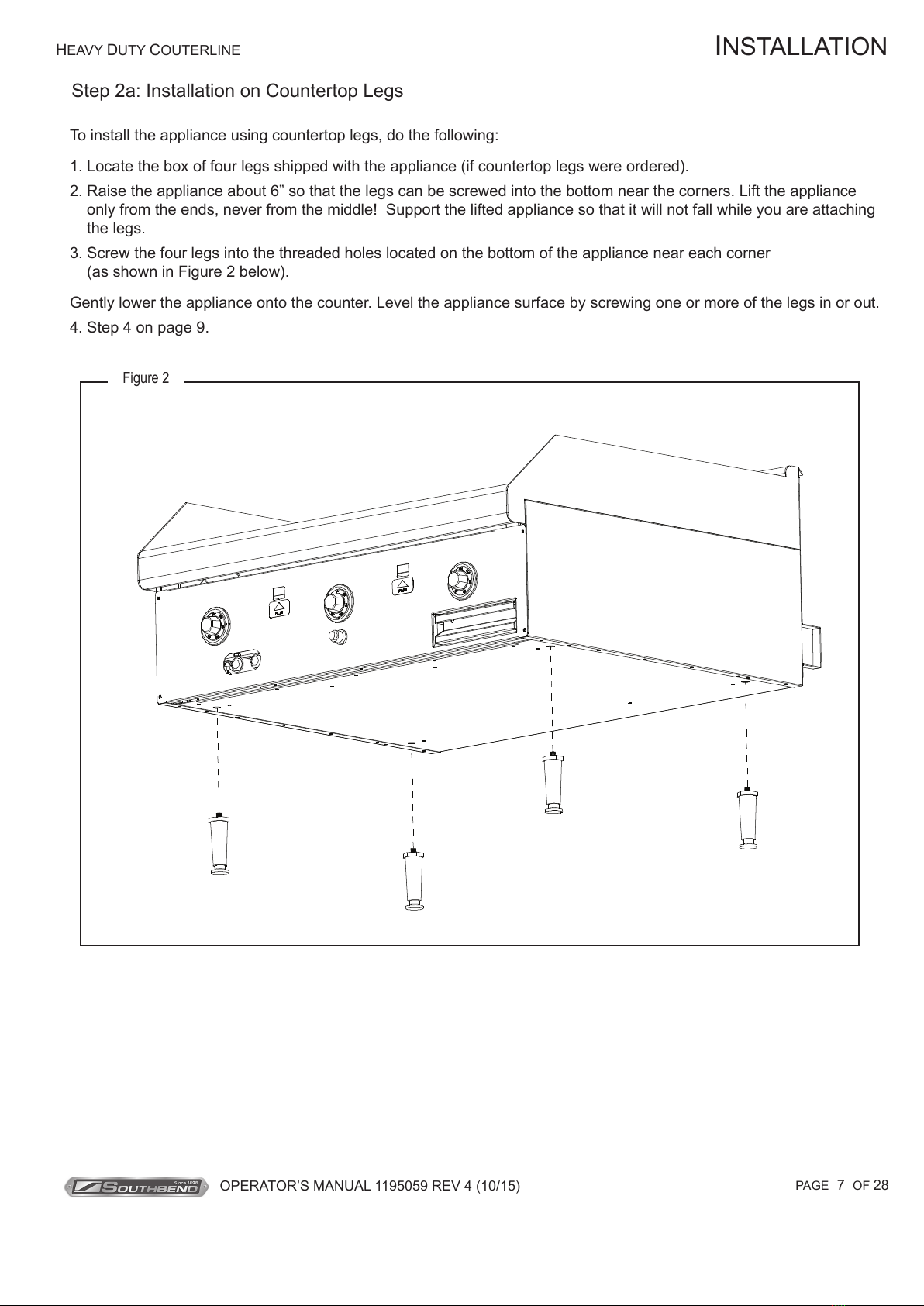
To install the appliance using countertop legs, do the following:
1. Locate the box of four legs shipped with the appliance (if countertop legs were ordered).
2. Raise the appliance about 6” so that the legs can be screwed into the bottom near the corners. Lift the appliance
only from the ends, never from the middle! Support the lifted appliance so that it will not fall while you are attaching
the legs.
3. Screw the four legs into the threaded holes located on the bottom of the appliance near each corner
(as shown in Figure 2 below).
Gently lower the appliance onto the counter. Level the appliance surface by screwing one or more of the legs in or out.
4. Step 4 on page 9.
Step 2a: Installation on Countertop Legs
INSTALLATION
Figure 2
Total Restaurant Supply - https://totalsupply1.com - Toll Free 1-800-944-9304 - Local 507-288-9454
2940 Hwy 14 W, Rochester, MN 55901

HEAVY DUTY COUTERLINE
OPERATOR’S MANUAL 1195059 REV 4 (10/15)
PAGE 8 OF 28
NOTICE
For an appliance equipped with casters, (1) the installation shall be made with a connector that complies with the
Standard for Connectors for Movable Gas Appliances, ANSI Z21.69 or Connectors for Moveable Gas Appliances,
CAN/CGA-6.16, and a quick-disconnect device that complies with the Standard for Quick-Disconnect Devices for
Use With Gas Fuel, ANSI Z21.41, or Quick Disconnect Devices for Use with Gas Fuel, CAN1-6.9, (2) adequate
means must be provided to limit the movement of the appliance without depending on the connector and the quick-
disconnect device or its associated piping to limit the appliance movement and (3) the restraining means should be
attached to a frame member on the back of the unit.
Step 3: Attach Restraint for Appliances Mounted on Casters
WARNING
To avoid accidental gas disconnection and potential explosion:
If disconnection of this restraint is necessary to move the appliance for cleaning, etc., reconnect it when the
appliance is moved to its originally installed position.
Appliances mounted on a stand with casters or other movable surface must be equipped with a restraining means to
prevent accidental stress on the exible gas connection.
1. Secure the restraining-device bracket (item “B” in the following illustration) to a wall stud located as close as possible
to the appliance connector inlet and outlet connections. Use four #12 screws (items “C”) and plastic anchors (items
“A”) if necessary.
INSTALLATION
HF
I
G
E
D
A
B
C
Note: Kit can be purchased from Southbend (part number 1176867).
Figure 3
Total Restaurant Supply - https://totalsupply1.com - Toll Free 1-800-944-9304 - Local 507-288-9454
2940 Hwy 14 W, Rochester, MN 55901
HEAVY DUTY COUTERLINE
OPERATOR’S MANUAL 1195059 REV 4 (10/15) PAGE 9 OF 28
2. Install eye-bolt (item “F”) to a frame member on the rear of the equipment. After checking carefully behind the frame
member for adequate clearance, drill a 1/4” hole through the frame member.
3. Thread hex nut (item “G”) and slide the washer (item “H”) onto the eye-bolt. Insert the eye-bolt through the 1/4” drilled
hole and secure with a washer (item “H”) and nylon lock nut (item “I”).
4. Using the spring-loaded snap hooks, attach the restraining device to the bracket and the eye-bolt.
5. Using the cable clamp (item “D”), adjust the restraining device extended length to prevent over-bending or kinking of
the appliance connector.
Note: For units not equipped with ame safety devices, be sure all valves are turned off prior to disconnecting.
After reconnecting, be sure that the oven is switched OFF.
Step 4: Connect Gas Supply
The serial plate is located interior side of the control panel (see Figure 1 on page 3). It indicates the type of gas the
appliance is equipped to burn. All Southbend equipment is adjusted at the factory. Check type of gas on serial plate.
This appliance should be connected ONLY to the type of gas for which it is equipped.
If the appliance is being installed at over 2,000 feet altitude and that information was not specied when ordered,
contact the appropriate authorized Southbend Service Representative or the Southbend Service Department. Failure to
install with proper orice sizing will result in poor performance and may void the warranty.
These models are design-certied for operation on natural or propane gases. For natural gas, the convertible regulator
shipped with the appliance is set to deliver a 4” W.C. pressure to the manifold. For propane gas, it is set to deliver 10”
W.C.
An adequate gas supply is imperative. Undersized or low pressure lines will restrict the volume of gas required for
satisfactory performance. A 1/8” pressure tap is located on the manifold to measure pressure.
Purge the supply line to clean out dust, dirt, or other foreign matter before connecting the line to the appliance.
Use pipe joint compound that is suitable for use with LP gas on all threaded connections.
INSTALLATION
CAUTION
ALL PIPE JOINTS AND CONNECTIONS MUST BE TESTED THOROUGHLY FOR GAS LEAKS. USE ONLY SOAPY
WATER FOR TESTING ON ALL GASES. NEVER USE AN OPEN FLAME TO CHECK FOR GAS LEAKS. ALL
CONNECTIONS MUST BE CHECKED FOR LEAKS AFTER THE APPLIANCE HAS BEEN PUT INTO OPERATION.
TEST PRESSURE SHOULD NOT EXCEED 14” W.C.
To connect the gas supply, do the following:
1. Check that the gas supply to the piping that will be connected to the appliance is shut off.
2. Check that all control knobs on the appliance are turned “OFF.”
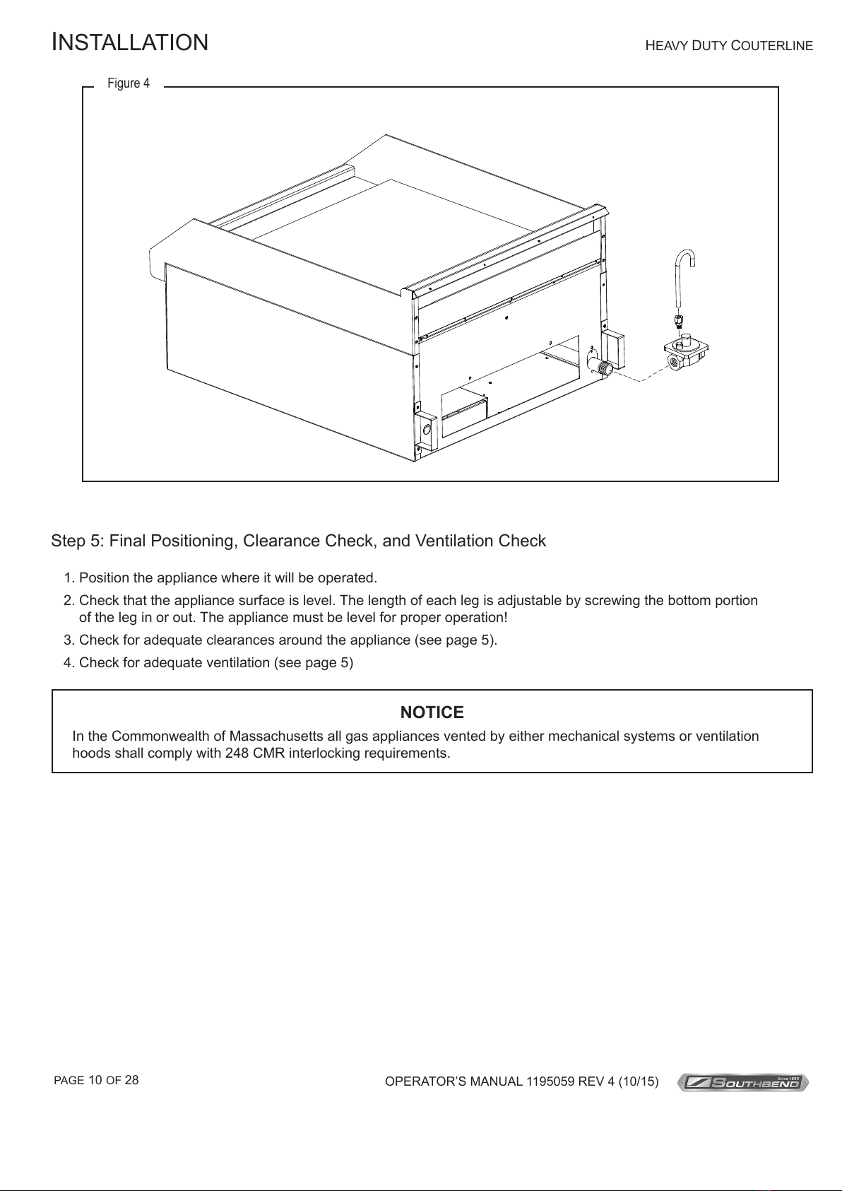
3. Attach the pressure regulator shipped with the appliance to the 3/4” NPT gas inlet connector located on the rear
of the appliance (see Figure 4 below). Be sure that the regulator is connected so that the gas ow is in the same
direction as the arrow on the bottom of the regulator.
4. Connect the vent line from the pressure regulator to the outdoors in accordance with local codes or, in the absence
of local codes, with the National Fuel Gas Code, ANSI Z223.1, Natural Gas Installation Code, CAN/CGA-B149.1, or
the Propane Installation Code, CAN/CGA-B149.2, as applicable.
5. Connect the gas inlet of the pressure regulator to the building’s supply system. No segment of the gas supply
connection to the appliance should be smaller than 3/4” NPT. Standard pipe ttings are required.
6. Turn on gas supply.
7. Check for leaks using soapy water.
Total Restaurant Supply - https://totalsupply1.com - Toll Free 1-800-944-9304 - Local 507-288-9454
2940 Hwy 14 W, Rochester, MN 55901
HEAVY DUTY COUTERLINE
OPERATOR’S MANUAL 1195059 REV 4 (10/15)
PAGE 10 OF 28
INSTALLATION
Figure 4
Step 5: Final Positioning, Clearance Check, and Ventilation Check
1. Position the appliance where it will be operated.
2. Check that the appliance surface is level. The length of each leg is adjustable by screwing the bottom portion
of the leg in or out. The appliance must be level for proper operation!
3. Check for adequate clearances around the appliance (see page 5).
4. Check for adequate ventilation (see page 5)
NOTICE
In the Commonwealth of Massachusetts all gas appliances vented by either mechanical systems or ventilation
hoods shall comply with 248 CMR interlocking requirements.
Total Restaurant Supply - https://totalsupply1.com - Toll Free 1-800-944-9304 - Local 507-288-9454
2940 Hwy 14 W, Rochester, MN 55901

HEAVY DUTY COUTERLINE
OPERATOR’S MANUAL 1195059 REV 4 (10/15) PAGE 11 OF 28
Step 6: Check Pilot and Burner Operation
All appliances are adjusted at the factory. However, pilot heights, burner air shutters, and thermostatic valves should
be checked at installation and adjusted if necessary. Do the following:
1. Turn main gas supply “ON”.
2. Check the manifold gas pressure using the procedure on page 19.
3. Light the pilots as described in the Operation section of this manual.
4. Check (and, if necessary, adjust) the pilot ame heights using the procedure on page 20.
5. Light the burners. Set the control knobs to only low temperatures for now.
6. Check (and, if necessary, adjust) the burner air shutters using the procedure on page 20.
INSTALLATION
Step 7: Final Installation Steps for Griddle Models
This step applies only to the installation of griddle models. New griddles should be carefully tempered and cared for
in order to avoid possible damage. To break in a new griddle, do the following:
1. Wipe the griddle surface clean.
2. Light all the griddle burners. For griddles with thermostatic controls, turn all knobs to 200°F for one hour. For
griddles with manual controls, turn all knobs to “LOW” for one hour. Then gradually bring each griddle up to frying
temperature.
3. Spread three or four ounces of beef suet, or as a substitute, baking soda, to season it. Never allow water on a hot
griddle and never wash it with soap and water.
4. For griddles with thermostatic controls, check (and, if necessary, adjust) the thermostatic valves that control the
griddle’s surface temperature. Follow the procedure on page 21.
Step 8: Final Installation Steps for Lava-Rock Charbroilers
This step applies only to the installation of lava-rock charbroiler models. Such models are shipped with the lava-rock
briquettes in bags located between the lava-rock grates and the top cooking grids.
1. Lift out the cooking grids to reach the bags of lava-rock briquettes.
2. For each section, open the bag of lava-rock briquettes and spread them evenly on the lava-rock grate. The
briquettes must be spread evenly to avoid “hot spots.” Discard the empty bags.
3. Reposition the cooking grids above the briquettes.
Total Restaurant Supply - https://totalsupply1.com - Toll Free 1-800-944-9304 - Local 507-288-9454
2940 Hwy 14 W, Rochester, MN 55901

HEAVY DUTY COUTERLINE
OPERATOR’S MANUAL 1195059 REV 4 (10/15)
PAGE 12 OF 28
OPERATION
DANGER
EXPLOSION HAZARD
Purchaser of equipment must post in a prominent location, detailed instructions to be followed in the event the
operator smells gas. Obtain the instructions from the local gas supplier.
CAUTION
To eliminate gas build up which could result in an explosion, in the event of main burner ignition failure a ve
minute purge period must be observed prior to re-establishing ignition source.
LIGHTING AFTER GAS HAS BEEN SHUT OFF
When turning the main gas supply on after the gas supply has been shut off, do the following:
1. Make sure all of the control valves are in the “OFF” position.
2. Turn on the gas supply.
3. Light the pilots as described in each section below.
OPERATION
CAUTION
Top section pilots, when out, do not interrupt the ow of gas to the burners. Consequently, it is the responsibility
of the operator to check the ignition of the burners, immediately after burner value has been turned “ON.” Should
ignition fail after 10 seconds, turn off burners, wait 5 minutes, and then try again.
WARNING
UNDER NO CIRCUMSTANCES IS A GRIDDLE TO BE USED FOR HEATING STOCK POTS. SUCH USE
AUTOMATICALLY VOIDS THE WARRANTY.
NEVER COOL A GRIDDLE BY APPLYING ICE OR WATER TO THE GRIDDLE SURFACE. DAMAGE DUE TO
MISUSE IS NOT COVERED BY THE WARRANTY.
DO NOT STRIKE A GRIDDLE SURFACE WITH THE EDGE OF COOKING IMPLEMENTS TO CLEAN THE
IMPLEMENTS. SUCH ACTION WILL CUT AND PIT THE GRIDDLE PLATE, LEAVING IT ROUGH AND HARD
TO CLEAN.
ALWAYS HEAT A GRIDDLE SLOWLY. DO NOT HEAT A GRIDDLE ABOVE 550°F.
Total Restaurant Supply - https://totalsupply1.com - Toll Free 1-800-944-9304 - Local 507-288-9454
2940 Hwy 14 W, Rochester, MN 55901

HEAVY DUTY COUTERLINE
OPERATOR’S MANUAL 1195059 REV 4 (10/15) PAGE 13 OF 28
OPERATION
OPERATION OF THERMOSTATIC GRIDDLE MODELS
Each 12”-wide and 18” wide model only griddle section has a thermostatic-control knob on the front panel that directly
controls the ow of gas, and so the heat. Turn the knob clockwise to increase the heat; turn it counterclockwise to reduce
the heat.
The griddle requires approximately 13 minutes of preheating to reach 350°F, and 45 minutes to even out.
Do not waste gas or abuse equipment by leaving control knobs set at a high temperature if not required. During idle
periods, set control knobs to low temperature settings to keep griddle warm.
After each period of use, allow the griddle surface to cool normally. At the end of each day’s use, turn all control knobs
to the “OFF” position. After the griddle has cooled, coat the griddle surface with a light lm of cooking oil to protect the
surface from moisture.
To shut down the appliance for an extended period (or before disconnecting the gas supply), turn all the burner control
gas knobs “OFF,”.
To light the pilots of a thermostatic griddle section, do the following:
1. Turn all griddle controls to the “OFF” position.
2. Note that the left pilot must be lit before the right pilot can be lit. For each pilot, press and hold the red pilot button
and light the pilot by pressing the electronic ignition button on the front panel to generate a spark. Continue to hold the
pilot button for 45 seconds, or until the pilot remains lit. Note that 18 & 24” models have one pilot, 36” & 48” models
have two pilots, 60” models have three pilots, and 72” models have four pilots.
3. If a pilot is extinguished or the gas supply is interrupted, wait ve minutes and repeat the above steps.
4. Allow the pilots to warm-up for 1 minute, then turn all griddle thermostat controls to the “ON” position to check that the
pilots will ignite the burners.
Figure 5
Note: 18” and 24” models have one pilot, 36” and 48” models have two pilots, 60” models have three pilots, and 72”
models have four pilots. 60” and 72” models have two shut-off valves, one in each burner compartment
Total Restaurant Supply - https://totalsupply1.com - Toll Free 1-800-944-9304 - Local 507-288-9454
2940 Hwy 14 W, Rochester, MN 55901

HEAVY DUTY COUTERLINE
OPERATOR’S MANUAL 1195059 REV 4 (10/15)
PAGE 14 OF 28
OPERATION OF MANUAL GRIDDLE MODELS
Each 12”-wide and 18” wide model only griddle section has a knob on the front panel that directly controls the ow of gas,
and so the heat. Turn the knob clockwise to increase the heat; turn it counterclockwise to reduce the heat.
After each period of use, allow the griddle surface to cool normally. At the end of each day’s use, turn all control knobs
to the “OFF” position. After the griddle has cooled, coat the griddle surface with a light lm of cooking oil to protect the
surface from moisture.
To shut down the appliance for an extended period (or before disconnecting the gas supply), turn all the burner control
gas knobs “OFF,” then turn the main gas supply valve(s) to “OFF.”
To light the pilots of a manual griddle section, do the following:
1. Turn all griddle controls to the “OFF” position.
2. Light the pilot tube located next to each burner. The pilot ame can be adjusted by turning the screw on the end of
the pilot tting.
3. Turn burner knobs to “HI” position. The burners should have a 1/2” to 5/8” steady blue ame. Adjust if necessary.
4. To turn burners off, turn knob to “OFF” position.
OPERATION
Figure 6
Left Pilot Right Pilot
(36" & 48" Models)
The drawing below shows a Model HDG-36-M with the front panels removed to show the interior parts.
Note: 24" models have one pilot, 36" and 48" models have two pilots, 60" models have three pilots, and 72" models have four pilots.
The pilots can be viewed and lit through openings on the
front panel (Model HDG-36-M shown).
Note: 18” and 24” models have one pilot, 36” and 48” models have two pilots, 60” models have three pilots, and 72”
models have four pilots
Total Restaurant Supply - https://totalsupply1.com - Toll Free 1-800-944-9304 - Local 507-288-9454
2940 Hwy 14 W, Rochester, MN 55901

HEAVY DUTY COUTERLINE
OPERATOR’S MANUAL 1195059 REV 4 (10/15) PAGE 15 OF 28
OPERATION OF CHARBROILER MODELS
OPERATION
Each 6”-wide charbroiler section has a knob on the front panel that directly controls the ow of gas, and so the
heat. Turn the knob counterclockwise to increase the heat; turn it clockwise to reduce the heat.
To use the charbroiler, turn all the control knobs to the full “ON” position. (If any burners do not light, check the pi-
lots and, if necessary, light the pilots as described later in this section.) After 15 to 20 minutes turn back the ame
to maintain enough heat to keep the bottom of the radiants or lava-rock grates hot. The radiants or grates will be at
broiling temperature throughout, providing the radiant heat that is essential to provide fast broiling.
By design, the front of the broiler grid is much hotter than the rear third. Use the rear of the charbroiler to quick-
ly sear both sides of meat to retain maximum juices. This fast cooking is one of the secrets of successful meat
broiling, and gives the meat that special “outdoor” avor. Cook rare meats at the back quickly; cook medium and
well-done meats closer to the front more slowly. Adjust the cooking time according to the thickness of the meat and
amount of doneness desired. If desired, move meat cooked rare to the very front to keep it warm while medium
and well-done meats are still cooking. Remember that to cook meat properly you must keep in mind both heat and
time.
The tilt angle of the charbroiler grid is adjustable by pulling up on the back of the grid. The tilted position is normal
and recommended. The tilt angle allows most fat rendered off meat during broiling to run into the grease trough,
thus eliminating excess aring of fats and accompanying smoke. Steaks and chops, being fattier than other meats,
will still have some aring up to give the desired broiling results while enough fat drains off to avoid severe ares.
Use the at position for heating on the top, or for continuous cooking of hot dogs and sausage. Fats dripping down
into the re will burn up on the meat to help give it that desirable special avor.
The heavy cast iron grids can be turned over for different “branding” width. One side has wide-branding (1/4”) and
the other side has narrow branding (1/8” with grease channel). Chrome-plated grids can be ordered for cooking
sh.
At the end of each day’s use, turn all knobs to the “OFF” position.
To shut down the appliance for an extended period (or before disconnecting the gas supply), turn all the burner
control gas knobs “OFF,” then turn the main gas supply valve to “OFF.”
To light the pilot(s) of a charbroiler section, do the following:
1. Turn all control knobs to the “OFF” position.
2. Light the pilot located next to each burner (accessed through front). If the pilot will not remain lit, have a service
technician adjust the pilot by turning the screw on the pilot tting.
3. Turn burner knobs to “HI” position. The burners should have a 1/2” to 5/8” steady blue ame. If they do not,
have them adjusted by a service technician.
4. To turn burners off, turn knob to “OFF” position.
Total Restaurant Supply - https://totalsupply1.com - Toll Free 1-800-944-9304 - Local 507-288-9454
2940 Hwy 14 W, Rochester, MN 55901

HEAVY DUTY COUTERLINE
OPERATOR’S MANUAL 1195059 REV 4 (10/15)
PAGE 16 OF 28
OPERATION
OPERATION OF OPEN-TOP BURNER MODELS
Each 12”-wide open-top burner section has two knobs on the front panel that directly control the ow of gas to the
section’s two burners, and so control the heat. Turn a knob clockwise to increase the heat; turn it counterclockwise
to reduce the heat.
If any burners do not light, check the pilots and, if necessary, light the pilots as described later in this section.
At the end of each day’s use, turn all knobs to the “OFF” position.
To shut down the appliance for an extended period (or before disconnecting the gas supply), turn all the burner
control gas knobs “OFF,” then turn the main gas supply valve to “OFF.”
To light the pilots of an open-top burner section, do the following:
1. Turn all gas valves to the “OFF” position.
2. Check to make sure pilots are in the correct position.
3. Light the pilots. If the pilots will not remain lit, have a service technician adjust them.
4. Turn burner knobs to “HI” position. Each burner ame should be steady blue and impinge on the underside of a
pot placed on the support grate. If necessary, have a service technician adjust the burners.
5. To turn burners off, turn knob to “OFF” position.
Total Restaurant Supply - https://totalsupply1.com - Toll Free 1-800-944-9304 - Local 507-288-9454
2940 Hwy 14 W, Rochester, MN 55901

HEAVY DUTY COUTERLINE
OPERATOR’S MANUAL 1195059 REV 4 (10/15) PAGE 17 OF 28
CLEANING
CLEANING
Daily:
• Remove, empty, and clean grease drawers of griddles and charbroilers.
• Clean griddle drain chutes of griddles.
Monthly:
• Clean around burner air mixers and orices if lint has accumulated.
• Visually assure proper pilot operation.
CARE OF CARBON STEEL GRIDDLE SURFACE
Never allow water on a hot griddle and never wash it with soap and water.
Use a Norton Alundum Griddle Brick to clean the griddle. Always remember to heat a griddle slowly because quick
heat may cause costly damage. Griddle plates cannot be guaranteed against damage due to carelessness. Never
place utensils on griddle. Do not overheat griddle above 550°F as this will cause warpage or breakage.
Do not use any type of steel wool. Small particles may be left on the surface and get into food products. Do not clean
a spatula by hitting the edge on the griddle plate. Such action will only cut and pit the griddle plate, leaving it rough
and hard to clean.
CARE OF CHROME PLATED GRIDDLE SURFACE
Allow griddle plate to cool down to approximately 200°F. Pour 8 ounces of water onto griddle surface. Apply a
non-abrasive degreaser to water on griddle surface. Using a non-abrasive brush, evenly spread degreaser solution
around entire griddle plate surface and use additional water if necessary to cover entire griddle plate. Allow time
to soak until grease begins to separate. Using a non-metallic scraper, remove remaining grease particles from the
griddle surface. Flush the entire griddle surface with clean water until all degreaser solution has been removed. Wipe
he entire griddle surface, back and splash walls with a clean damp cloth.
Southbend equipment is constructed with the best quality materials and is designed to provide durable service
when properly maintained. To expect the best performance, your equipment must be maintained in good condition
and cleaned daily. Naturally, the frequency and extent of cleaning depends on the amount and degree of usage.
CARE OF STAINLESS STEEL SURFACES
To remove normal dirt, grease and food residue from stainless steel that operates at LOW temperature, use ordinary
soap and water (with or without detergent) applied with a sponge or cloth. Dry thoroughly with a clean cloth.
To remove grease, food splatter, or condensed vapors that have BAKED onto the equipment, apply cleanser to a
damp cloth or sponge and rub cleanser on the metal in the direction of the polishing lines on the metal. Rubbing
cleanser, as gently as possible, in the direction of the polished lines will not mar the nish of the stainless steel.
NEVER RUB WITH A CIRCULAR MOTION. Soil and burnt deposits which do not respond to the above procedure
can usually be removed by rubbing the surface with SCOTCH-BRITE scouring pads or STAINLESS scouring
pads. DO NOT USE ORDINARY STEEL WOOL, as any particles left on the surface will rust and further spoil
the appearance of the nish. NEVER USE A WIRE BRUSH, STEEL SCOURING PADS (EXCEPT STAINLESS),
SCRAPER, FILE OR OTHER STEEL TOOLS. Surfaces that are marred collect dirt more rapidly and become more
difcult to clean. Marring also increases the possibility of corrosive attack. Renishing may then be required.
Total Restaurant Supply - https://totalsupply1.com - Toll Free 1-800-944-9304 - Local 507-288-9454
2940 Hwy 14 W, Rochester, MN 55901

HEAVY DUTY COUTERLINE
OPERATOR’S MANUAL 1195059 REV 4 (10/15)
PAGE 18 OF 28
“Heat tint” is a darkened area that can appear on a stainless steel surface where the area has been subjected to exces-
sive heat. These darkened areas are caused by thickening of the protective surface of the stainless steel and are not
harmful. Heat tint can normally be removed by the foregoing, but tint which does not respond to this procedure calls for a
vigorous scouring in the direction of the polish lines, using SCOTCH-BRITE scouring pads or a STAINLESS scouring pad
in combination with a powered cleanser. Heat tint action may be lessened by not applying, or by reducing heat to equip-
ment during slack periods.
CLEANING
Total Restaurant Supply - https://totalsupply1.com - Toll Free 1-800-944-9304 - Local 507-288-9454
2940 Hwy 14 W, Rochester, MN 55901

HEAVY DUTY COUTERLINE
OPERATOR’S MANUAL 1195059 REV 4 (10/15) PAGE 19 OF 28
ADJUSTMENTS
WARNING
ADJUSTMENTS AND SERVICE WORK MAY BE PERFORMED ONLY BY A QUALIFIED TECHNICIAN WHO IS
EXPERIENCED IN, AND KNOWLEDGEABLE WITH, THE OPERATION OF COMMERCIAL COOKING EQUIPMENT.
HOWEVER, TO ASSURE YOUR CONFIDENCE, CONTACT YOUR AUTHORIZED SERVICE AGENCY FOR
RELIABLE SERVICE, DEPENDABLE ADVICE OR OTHER ASSISTANCE, AND FOR GENUINE FACTORY PARTS.
Before making any adjustment, make sure the appliance is connected to the type of gas for which it is equipped. That
information is on the serial plate, which is located on the inside of the control panel (see Figure 1 on page 3).
ADJUSTMENT OF MANIFOLD GAS PRESSURE
A pressure regulator is connected to the appliance’s gas connection, outside the rear left corner of the appliance. The
pressure regulator is factory set at 4” W.C. for natural gas and 10” W.C. for propane. To check the manifold pressure, do
the following:
1. Turn all burner valves to “OFF” position.
2. Turn main gas valve to entire appliance off.
3. Remove front panel and locate 1/8” plug in manifold. (Note that 60” and 72” griddle models have two burner
compartments, and so have two manifolds.)
4. Remove the plug and install a tting appropriate to connect a manometer.
5. Turn on main gas to appliance and light pilots.
6. Turn all burners to full “ON” position and read manometer.
7. If manometer does not read 4” W.C. for natural gas (or 10” W.C. for propane gas), check the incoming gas line
for proper pressure. The proper gas line pressure is 5-7” W.C. for natural gas and 11-14” W.C. for propane.
8. Remove manometer tting and replace plug in manifold.
9. Replace front panel.
10. Turn on main gas to appliance and light pilots.
NOTICE
The warranty will be void and the manufacturer relieved of all responsibility if…
(A) Service work is performed by other than a qualied technician, or
(B) Other than genuine Southbend replacement parts are installed.
ADJUSTMENTS
Total Restaurant Supply - https://totalsupply1.com - Toll Free 1-800-944-9304 - Local 507-288-9454
2940 Hwy 14 W, Rochester, MN 55901
HEAVY DUTY COUTERLINE
OPERATOR’S MANUAL 1195059 REV 4 (10/15)
PAGE 20 OF 28
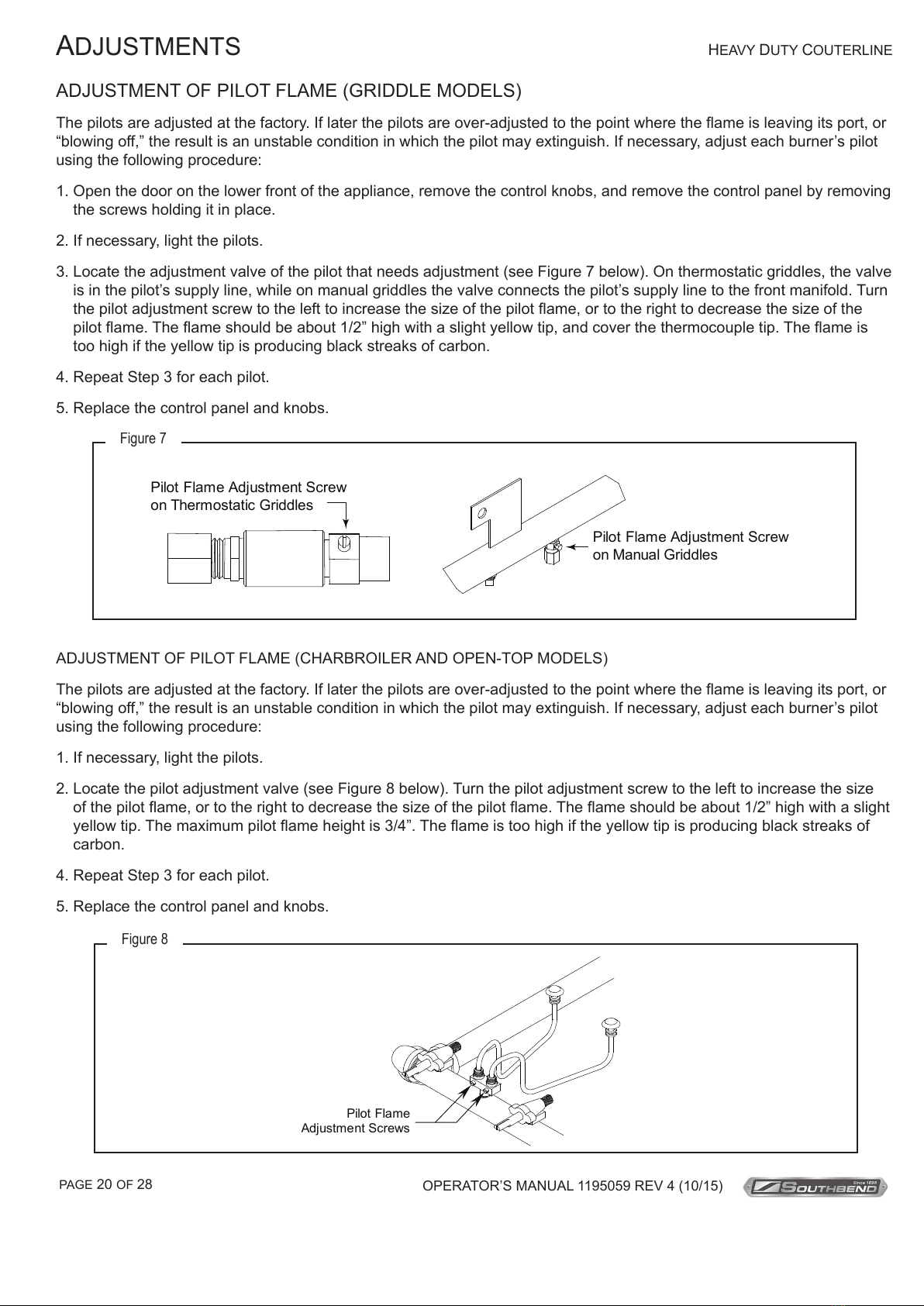
ADJUSTMENT OF PILOT FLAME (GRIDDLE MODELS)
The pilots are adjusted at the factory. If later the pilots are over-adjusted to the point where the ame is leaving its port, or
“blowing off,” the result is an unstable condition in which the pilot may extinguish. If necessary, adjust each burner’s pilot
using the following procedure:
1. Open the door on the lower front of the appliance, remove the control knobs, and remove the control panel by removing
the screws holding it in place.
2. If necessary, light the pilots.
3. Locate the adjustment valve of the pilot that needs adjustment (see Figure 7 below). On thermostatic griddles, the valve
is in the pilot’s supply line, while on manual griddles the valve connects the pilot’s supply line to the front manifold. Turn
the pilot adjustment screw to the left to increase the size of the pilot ame, or to the right to decrease the size of the
pilot ame. The ame should be about 1/2” high with a slight yellow tip, and cover the thermocouple tip. The ame is
too high if the yellow tip is producing black streaks of carbon.
4. Repeat Step 3 for each pilot.
5. Replace the control panel and knobs.
Figure 7
P
ilot Flame Adjustment Screw
o
n Thermostatic Griddles
Pilot Flame Adjustment Screw
on Manual Griddles
ADJUSTMENT OF PILOT FLAME (CHARBROILER AND OPEN-TOP MODELS)
The pilots are adjusted at the factory. If later the pilots are over-adjusted to the point where the ame is leaving its port, or
“blowing off,” the result is an unstable condition in which the pilot may extinguish. If necessary, adjust each burner’s pilot
using the following procedure:
1. If necessary, light the pilots.
2. Locate the pilot adjustment valve (see Figure 8 below). Turn the pilot adjustment screw to the left to increase the size
of the pilot ame, or to the right to decrease the size of the pilot ame. The ame should be about 1/2” high with a slight
yellow tip. The maximum pilot ame height is 3/4”. The ame is too high if the yellow tip is producing black streaks of
carbon.
4. Repeat Step 3 for each pilot.
5. Replace the control panel and knobs.
Figure 8
Pilot Flame
A
djustment Screws
ADJUSTMENTS
Total Restaurant Supply - https://totalsupply1.com - Toll Free 1-800-944-9304 - Local 507-288-9454
2940 Hwy 14 W, Rochester, MN 55901
This manual suits for next models
28
Table of contents
Other Southbend Griddle manuals


Popular Griddle manuals by other brands

Continental Electric
Continental Electric CE23711 instruction manual

Black Stone
Black Stone PATIO 1962 owner's manual

BRIKA
BRIKA BMG-24 product manual

Vulcan-Hart
Vulcan-Hart VCCG36 Installation & operation manual

Garland
Garland ECG-24R Installation and operation manual

Simogas
Simogas EXTREME Series quick start guide


Moffat
Moffat Waldorf GP8600E-B Technical data sheet

Commercial Pro
Commercial Pro CPG24 instruction manual

Adexa
Adexa GG360 instruction manual

Roller Grill
Roller Grill PSF 600 E Instructions for use and installation

Accu-Steam
Accu-Steam GG24A Installation & operator's manual

Presto
Presto 7034 instructions