Southbend SB1494 User manual

®
A Tradition of Excellence
South Bend Tools
© February, 2021 by South Bend Tools For Machines Mfd. Since 1/21
MODEL SB1494
10" VARIABLE-SPEED HD BENCH GRINDER
OWNER'S MANUAL

Customer Service
We stand behind our machines. If you have any service questions, parts requests or general questions
about your purchase, feel free to contact us.
South Bend Tools
P.O. Box 2027
Bellingham, WA 98227
Phone: (360) 734-1540
Fax: (360) 676-1075 (International)
Fax: (360) 734-1639 (USA Only)
Email: [email protected]
Updates
For your convenience, any updates to this manual will be available to download free of charge
through our website at:
www.southbendtools.com
Scope of Manual
This manual helps the reader understand the machine, how to prepare it for operation, how to control
it during operation, and how to keep it in good working condition. We assume the reader has a basic
understanding of how to operate this type of machine, but that the reader is not familiar with the
controls and adjustments of this specific model. As with all machinery of this nature, learning the
nuances of operation is a process that happens through training and experience. If you are not an
experienced operator of this type of machinery, read through this entire manual, then learn more
from an experienced operator, schooling, or research before attempting operations. Following this
advice will help you avoid serious personal injury and get the best results from your work.
Manual Feedback
We've made every effort to be accurate when documenting this machine. However, errors sometimes
happen or the machine design changes after the documentation process—so
the manual may not
exactly match your machine.
If a difference between the manual and machine leaves you in doubt,
contact our
customer service for clarification.
We highly value customer feedback on our manuals. If you have a moment, please share your
experience using this manual. What did you like about it? Is there anything you would change to
make it better? Did it meet your expectations for clarity, professionalism, and ease-of-use?
South Bend Tools
C
/O Technical Documentation Manager

Table of Contents
ACCESSORIES.............................................................. 26
MAINTENANCE ............................................................. 27
Maintenance Schedule....................................... 27
Grinding Wheels ................................................27
Lubrication......................................................... 27
Cleaning .............................................................27
Wheel Dressing ..................................................27
TROUBLESHOOTING................................................. 28
ELECTRICAL...................................................................30
Electrical Safety Instructions ...........................30
Wiring Diagram (110V) .....................................31
Wiring Diagram (220V) .....................................32
Electrical Component Pictures..........................33
PARTS................................................................................34
Main....................................................................34
Machine Labels ..................................................36
WARRANTY..................................................................... 37
INTRODUCTION...............................................................2
Identification ........................................................2
Description of Controls & Components ..............3
Product Specifications ......................................... 4
SAFETY................................................................................6
Understanding Risks of Machinery ....................6
Basic Machine Safety ..........................................6
Additional Safety for Grinders............................ 8
PREPARATION .................................................................9
Preparation Overview.......................................... 9
Required for Setup...............................................9
Power Supply Requirements............................. 10
Unpacking ..........................................................12
Inventory ............................................................12
Cleaning & Protecting .......................................13
Location ..............................................................14
Bench Mounting................................................. 14
Assembly ............................................................15
Power Connection ..............................................17
Test Run .............................................................19
OPERATION.................................................................... 21
Operation Overview...........................................21
Workpiece Inspection......................................... 22
Selecting Grinding Wheel.................................. 22
Caring for Grinding Wheel................................ 23
Inspecting Grinding Wheel ............................... 23
Dressing Grinding Wheel .................................. 24
Storing Grinding Wheel.....................................24
Installing/Removing Grinding Wheel ...............24
Like all machinery there is potential danger
when operating this machine. Accidents are
frequently caused by lack of familiarity or
failure to pay attention. Use this machine with
respect and caution to decrease the risk of
operator injury. If normal safety precautions
are overlooked or ignored, serious personal
injury may occur.
No list of safety guidelines can be complete.
Every shop environment is different. Always
consider safety first, as it applies to your
individual working conditions. Use this and
other machinery with caution and respect.
Failure to do so could result in serious
personal injury, damage to equipment, or poor
work results.

INTRODUCTION
-2-
For Machines Mfd. Since 1/21
South Bend Tools
Model SB1494 INTRODUCTION
Identification
Untrained users have an increased risk
of seriously injuring themselves with this
machine. Do not operate this machine until
you have understood this entire manual and
received proper training.
LED Work Light
Eye Shield
ON/OFF Switch
w/Disabling Key
Variable-Speed
Dial
Digital Tachometer
Work Rest
Eye Shield
Lock Knobs
Grinding
Wheel
Spark Hood
Work Rest
Lock Handles
Wheel Guard
Spark
Deflector
For Your Own Safety Read Instruction
Manual Before Operating Grinder
1) Wear eye protection.
2) Use grinding wheel suitable for speed of
grinder.

South Bend Tools
For Machines Mfd. Since 1/21 Model SB1494
-3-
INTRODUCTION
Description of Controls
& Components
Refer to Figures 1–3 and the following
descriptions to become familiar with the basic
controls and components used to operate this
machine.
A. Eye Shield: Protects against sparks during
operations. This shield is not a substitute for
personal protective equipment.
B. Spark Deflector: Reduces amount of sparks
spraying back towards operator so wheel
guard will contain them until they cool.
C. Eye Shield Lock Knobs: Loosen to adjust eye
shield position and tighten to secure.
D. LED Work Light: Illuminates grinding area
for better visibility. Turns ON when machine
is turned ON.
E. Work Rest Lock Handles: Loosen to adjust
work rest position and tighten to secure.
F. Work Rest: Provides flat surface to rest
workpiece on during operations.
K
Figure 3. Wheel components.
G. ON/OFF Switch w/Disabling Key: Turns
motor ON when moved up; turns motor OFF
when moved down. When key is removed,
switch is disabled and machine cannot start.
H. Variable-Speed Dial: Rotates to adjust
grinding speed. Variable-speed dial must be
turned fully counterclockwise for motor to
start.
I. Digital Tachometer: Displays spindle RPM.
I
GH
Figure 2. Control panel components.
AB
Figure 1. Adjustable components.
J. Wheel Guard: Prevents accidental
contact with grinding wheel and contains
particulates and sparks produced while
grinding.
K. Grinding Wheel: Spins to grind workpiece.
C
D
F
E
J

-4-
For Machines Mfd. Since 1/21
South Bend Tools
Model SB1494 INTRODUCTION
Product Specifications
Model SB1494 Page 1 of 2
Model SB1494
10" VariableSpeed HeavyDuty Bench Grinder
Product Dimensions
Weight............................................................................................................................................................. 123 lbs.
Width (side-to-side) x Depth (front-to-back) x Height......................................................... 24 x 17-1/2 x 18-1/2 in.
Footprint (Length x Width)......................................................................................................................... 10 x 7 in.
Shipping Dimensions
Type............................................................................................................................................................ Cardboard
Content.......................................................................................................................................................... Machine
Weight............................................................................................................................................................. 149 lbs.
Length x Width x Height................................................................................................................... 28 x 22 x 19 in.
Electrical
Power Requirement........................................................................................... 110V or 220V, Single-Phase, 60 Hz
Prewired Voltage................................................................................................................................................ 110V
Full-Load Current Rating................................................................................................. 7A at 110V, 3.5A at 220V
Minimum Circuit Size.......................................................................................................................................... 15A
Connection Type..................................................................................................................................... Cord & Plug
Power Cord Included............................................................................................................................................. Yes
Power Cord Length............................................................................................................................................ 72 in.
Power Cord Gauge......................................................................................................................................... 16 AWG
Plug Included........................................................................................................................................................ Yes
Included Plug Type.............................................................................................................................................. 5-15
Recommended Plug Type..................................................................................................................... 6-15 for 220V
Switch Type.......................................................................................................... Toggle ON/OFF w/Disabling Key
Motors
Main
Horsepower......................................................................................................................................... 1-1/2 HP
Phase............................................................................................................................................ Single-Phase
Amps..................................................................................................................................................... 7A/3.5A
Speed....................................................................................................................................... 900 - 2400 RPM
Type........................................................................................................................................ TEFC Induction
Power Transfer ...................................................................................................................................... Direct
Bearings................................................................................................ Shielded & Permanently Lubricated
Model SB1494 Page 1 of 2
Model SB1494
10" VariableSpeed Heavy Duty Bench Grinder
Product Dimensions
Weight............................................................................................................................................................. 123 lbs.
Width (side-to-side) x Depth (front-to-back) x Height......................................................... 24 x 17-1/2 x 18-1/2 in.
Footprint (Length x Width)......................................................................................................................... 10 x 7 in.
Shipping Dimensions
Type............................................................................................................................................................ Cardboard
Content.......................................................................................................................................................... Machine
Weight............................................................................................................................................................. 149 lbs.
Length x Width x Height................................................................................................................... 28 x 22 x 19 in.
Electrical
Power Requirement........................................................................................... 110V or 220V, Single-Phase, 60 Hz
Prewired Voltage................................................................................................................................................ 110V
Full-Load Current Rating................................................................................................. 7A at 110V, 3.5A at 220V
Minimum Circuit Size.......................................................................................................................................... 15A
Connection Type..................................................................................................................................... Cord & Plug
Power Cord Included............................................................................................................................................. Yes
Power Cord Length............................................................................................................................................ 72 in.
Power Cord Gauge......................................................................................................................................... 16 AWG
Plug Included........................................................................................................................................................ Yes
Included Plug Type.............................................................................................................................................. 5-15
Recommended Plug Type..................................................................................................................... 6-15 for 220V
Switch Type.......................................................................................................... Toggle ON/OFF w/Disabling Key
Motors
Main
Horsepower......................................................................................................................................... 1-1/2 HP
Phase............................................................................................................................................ Single-Phase
Amps..................................................................................................................................................... 7A/3.5A
Speed....................................................................................................................................... 900 - 2400 RPM
Type........................................................................................................................................ TEFC Induction
Power Transfer ...................................................................................................................................... Direct
Bearings................................................................................................ Shielded & Permanently Lubricated

South Bend Tools
For Machines Mfd. Since 1/21 Model SB1494
-5-
INTRODUCTION
Model SB1494 Page 2 of 2
Main Specifications
Operation Info
Grinder Type...................................................................................................................................... Benchtop
Wheel Type............................................................................................................................................. Type 1
Right Wheel Grit................................................................................................................................... 40-Grit
Left Wheel Grit..................................................................................................................................... 60-Grit
Wheel Material..................................................................................................................... Aluminum Oxide
Wheel Diameter....................................................................................................................................... 10 in.
Wheel Thickness........................................................................................................................................ 1 in.
Minimum Speed Rating of Grinding Wheel................................................................................... 2400 RPM
Spindle Diameter....................................................................................................................................... 1 in.
Work Rest.................................................................................................................................................... Yes
Dust Port..................................................................................................................................................... Yes
Construction
Base.................................................................................................................................................... Cast Iron
Work Rest.................................................................................................................................................. Steel
Lamp.......................................................................................................................................................... LED
Other
Country of Origin ........................................................................................................................................... Taiwan
Warranty ........................................................................................................................................................ 2 Years
Serial Number Location .............................................................................................................................. ID Label
ISO 9001 Factory ................................................................................................................................................. Yes
Features
Spindle Speed Digital Tachometer
Variable-Speed Dial
Adjustable Eye Safety Shields, Work Rests, and LED Work Light
Cast-Iron Base
Two 2-1/2" Dust Ports with Spark Guards

SAFETY
-6-
For Machines Mfd. Since 1/21
South Bend Tools
Model SB1494 SAFETY
Understanding Risks of Machinery
Operating all machinery and machining equipment can be dangerous or relatively safe depending
on how it is installed and maintained, and the operator's experience, common sense, risk awareness,
working conditions, and use of personal protective equipment (safety glasses, respirators, etc.).
The owner of this machinery or equipment is ultimately responsible for its safe use. This
responsibility includes proper installation in a safe environment, personnel training and usage
authorization, regular inspection and maintenance, manual availability and comprehension,
application of safety devices, integrity of cutting tools or accessories, and the usage of approved
personal protective equipment by all operators and bystanders.
The manufacturer of this machinery or equipment will not be held liable for injury or property
damage from negligence, improper training, machine modifications, or misuse. Failure to read,
understand, and follow the manual and safety labels may result in serious personal injury, including
amputation, broken bones, electrocution, or death.
The signals used in this manual to identify hazard levels are as follows:
Death or catastrophic
harm WILL occur.
Moderate injury or fire
MAY occur.
Death or catastrophic
harm COULD occur.
Machine or property
damage may occur.
Basic Machine Safety
Owner’s Manual: All machinery and machining
equipment presents serious injury hazards
to untrained users. To reduce the risk of
injury, anyone who uses THIS item MUST
read and understand this entire manual
before starting.
Personal Protective Equipment: Operating or
servicing this item may expose the user
to flying debris, dust, smoke, dangerous
chemicals, or loud noises. These hazards
can result in eye injury, blindness, long-
term respiratory damage, poisoning,
cancer, reproductive harm or hearing loss.
Reduce your risks from these hazards
by wearing approved eye protection,
respirator, gloves, or hearing protection.
Trained/Supervised Operators Only: Untrained
users can seriously injure themselves
or bystanders. Only allow trained and
properly supervised personnel to operate
this item. Make sure safe operation
instructions are clearly understood. If
electrically powered, use padlocks and
master switches, and remove start switch
keys to prevent unauthorized use or
accidental starting.
Guards/Covers: Accidental contact with
moving parts during operation may cause
severe entanglement, impact, cutting,
or crushing injuries. Reduce this risk by
keeping any included guards/covers/doors
installed, fully functional, and positioned
for maximum protection.

South Bend Tools
For Machines Mfd. Since 1/21 Model SB1494
-7-
SAFETY
Entanglement: Loose clothing, gloves, neckties,
jewelry or long hair may get caught in
moving parts, causing entanglement,
amputation, crushing, or strangulation.
Reduce this risk by removing/securing
these items so they cannot contact moving
parts.
Mental Alertness: Operating this item with
reduced mental alertness increases the
risk of accidental injury. Do not let a
temporary influence or distraction lead to a
permanent disability! Never operate when
under the influence of drugs/alcohol, when
tired, or otherwise distracted.
Safe Environment: Operating electrically
powered equipment in a wet environment
may result in electrocution; operating near
highly flammable materials may result in a
fire or explosion. Only operate this item in
a dry location that is free from flammable
materials.
Electrical Connection: With electically powered
equipment, improper connections to the
power source may result in electrocution
or fire. Always adhere to all electrical
requirements and applicable codes when
connecting to the power source. Have all
work inspected by a qualified electrician to
minimize risk.
Disconnect Power: Adjusting or servicing
electrically powered equipment while it
is connected to the power source greatly
increases the risk of injury from accidental
startup. Always disconnect power
BEFORE any service or adjustments,
including changing blades or other tooling.
Secure Workpiece/Tooling: Loose workpieces,
cutting tools, or rotating spindles can
become dangerous projectiles if not
secured or if they hit another object during
operation. Reduce the risk of this hazard
by verifying that all fastening devices are
properly secured and items attached to
spindles have enough clearance to safely
rotate.
Chuck Keys or Adjusting Tools: Tools used to
adjust spindles, chucks, or any moving/
rotating parts will become dangerous
projectiles if left in place when the machine
is started. Reduce this risk by developing
the habit of always removing these tools
immediately after using them.
Work Area: Clutter and dark shadows increase
the risks of accidental injury. Only operate
this item in a clean, non-glaring, and well-
lighted work area.
Properly Functioning Equipment: Poorly
maintained, damaged, or malfunctioning
equipment has higher risks of causing
serious personal injury compared to
those that are properly maintained.
To reduce this risk, always maintain
this item to the highest standards and
promptly repair/service a damaged or
malfunctioning component. Always follow
the maintenance instructions included in
this documentation.
Unattended Operation: Electrically powered
equipment that is left unattended while
running cannot be controlled and is
dangerous to bystanders. Always turn the
power OFF before walking away.
Health Hazards: Certain cutting fluids and
lubricants, or dust/smoke created when
cutting, may contain chemicals known to
the State of California to cause cancer,
respiratory problems, birth defects,
or other reproductive harm. Minimize
exposure to these chemicals by wearing
approved personal protective equipment
and operating in a well ventilated area.
Difficult Operations: Attempting difficult
operations with which you are unfamiliar
increases the risk of injury. If you
experience difficulties performing the
intended operation, STOP! Seek an
alternative method to accomplish the
same task, ask a qualified expert how the
operation should be performed, or contact
our Technical Support for assistance.

-8-
For Machines Mfd. Since 1/21
South Bend Tools
Model SB1494 SAFETY
Additional Safety for Grinders
Spark Deflector Gap. Keep gap between end of
spark deflector and grinding wheel between
1⁄8"and 1⁄4". If gap is larger, pinch hazard
increases and excessive sparks/abrasives can
be expelled toward operator.
Wheel Attachment. Only use flanges included
with grinder when mounting wheels. Other
flanges may not properly secure wheel and
cause an accident. Do not use warped or
damaged flanges and always use paper discs
(blotters) between wheels and flanges to
reduce risk of flanges cracking wheel when
tightened. Only tighten wheel spindle nut
enough to drive wheel and prevent slippage.
Eye Shields. Place eye shields close to grinding
wheel and re-adjust as wheel wears down.
Tool Rest Position. If tool rest is too far away
from wheel, it forms an “in-running nip
point"gap which may cause workpiece to be
pulled down, leading to loss of control and
pulling your hand into grinding wheel. Keep
tool rest within 1⁄8"of wheel when operating
to minimize risk of pinching and crushing
injuries. Replace grinding wheel when tool
rest gap is wider than 1⁄8", and when no
additional adjustment can be made.
Handle & Wheel Contact. Keep a firm grip on
workpiece and position your hands a safe
distance away when grinding. Anticipate
when workpiece will heat up, and cool it
before it becomes too hot to hold, or use
appropriate clamp. Avoid wearing gloves as
they may get caught in grinding wheel and
cause more serious entanglement injuries.
Safe Mounting & Work Area. An unsecured
grinder may become dangerously out of
control during operation. Before use, verify
grinder is FIRMLY secured in location
free of explosive or flammable materials.
Frequently clean grinding dust from beneath
grinder and inside wheel cover.
Starting Grinder. If wheel is damaged, it will
usually fly apart shortly after start-up. To
protect yourself, always stand to side of
grinder when turning it ON and allow it to
run for at least one minute before standing
in front of it. Never grind with wheel that
vibrates.
Wheel Inspection. Verify grinding wheels are free
of cracks, chips, or dents in wheel surface
before installing. Do not use wheel if it has
any of these problems or it could break apart
during operation. Replace wheel or shaft
bearings immediately. Perform a “ring test”
on grinding wheels before installation to
ensure they are safe to use. A wheel that
does NOT pass ring test may break or fly
apart during operation.
Wheel Speed Rating. Wheels operated at a faster
speed than rated for may break apart during
operation. Before mounting new wheel, be
sure wheel RPM rating is equal to or higher
than speed of grinder. Never use unmarked
wheels or wheel rated for lower speed than
grinder.
Avoiding Entanglement. Becoming entangled
in moving parts can cause severe injury or
death. Keep all guards and covers in place;
DO NOT wear loose clothing, gloves, or
jewelry; and tie back long hair.
Eye, Face, & Lung Protection. Grinding ejects
small particles at high rate of speed. These
particles can cause blindness, skin injuries,
or respiratory damage. ALWAYS wear
approved clothing, safety goggles, face
shield, and respirator for type of grinding.
Side & Top Grinding. Grinding on side of wheels
can cause them to crack and burst—unless
wheel is rated for side grinding. Grinding
on top of wheels greatly increases risk
of workpiece kickback. Always grind on
downward part of wheel.
Serious injury or death can occur from impact injuries if grinding wheel breaks apart during use.
Entanglement/amputation injuries can occur from being caught in moving parts or in-running
pinch points. Flying sparks can ignite explosive or flammable materials. Rotating grinding wheels
can easily remove skin. To minimize risk of getting hurt or killed, anyone operating machine MUST
completely heed hazards and warnings below.
PREPARATION
South Bend Tools
For Machines Mfd. Since 1/21 Model SB1494
-9-
PREPARATION
Preparation Overview Required for Setup
The items listed below are required to
successfully set up and prepare this machine for
operation.
For Power Connection
• A power source that meets the minimum
circuit requirements for this machine. (Refer
to the Power Supply Requirements
section for details.)
For Assembly
• Safety Glasses for Each Person
• Disposable Rags
• Disposable Gloves
• Cleaner/Degreaser
• Mounting Hardware 3/8" (As Needed)
• Hex Wrench 3⁄16"
• Phillips Head Screwdriver #2
• Wrench or Socket 7⁄16"
The purpose of the preparation section is to help
you prepare your machine for operation. The list
below outlines the basic process. Specific steps
for each of these points will be covered in detail
later in this section.
The typical preparation process is as follows:
1. Unpack the machine and inventory the
contents of the box/crate.
2. Clean the machine and its components.
3. Identify an acceptable location for the
machine and move it to that location.
4. Bolt the machine to a workbench or stand.
5. Assemble the loose components and make
any necessary adjustments or inspections to
ensure the machine is ready for operation.
6. Connect the machine to the power source. Incorrect use of this
machine can result in
death or serious injury.
For your own safety, read
and understand this entire
document before using.
Wear safety glasses during
the entire setup process!
HEAVY LIFT!
Straining or crushing injury
may occur from improperly
lifting machine. To reduce
this risk, get help from other
people or lifting equipment
rated for weight of this
machine.
7. Test run the machine to make sure it
functions properly and is ready for operation.
Serious injury could occur if you connect
the machine to power before completing the
setup process. DO NOT connect to power until
instructed later in this manual.

-10-
For Machines Mfd. Since 1/21
South Bend Tools
Model SB1494 PREPARATION
Power Supply
Requirements
Electrocution or fire may
occur if machine is not
correctly grounded and
attached to the power
supply. Use a qualified
electrician to ensure a safe
power connection.
Before installing the machine, consider the
availability and proximity of the required power
supply circuit. If an existing circuit does not meet
the requirements for this machine, a new circuit
must be installed.
To minimize the risk of electrocution, fire,
or equipment damage, installation work and
electrical wiring must be done by a
n electrician
or qualified service personnel
in accordance with
applicable electrical codes and safety standards.
Availability
The full-load current rating is the amperage
a machine draws at 100% of the rated output
power. On machines with multiple motors, this is
the amperage drawn by the largest motor or sum
of all motors and electrical devices that might
operate at one time during normal operations.
The full-load current is not the maximum
amount of amps that the machine will draw. If
the machine is overloaded, it will draw additional
amps beyond the full-load rating.
If the machine is overloaded for a sufficient
length of time, damage, overheating, or fire may
result—especially if connected to an undersized
circuit. To reduce the risk of these hazards,
avoid overloading the machine during operation
and make sure it is connected to a power supply
circuit that meets the requirements in the
following section.
Full-Load Current Rating
Full-Load Rating at 110V..................... 7 Amps
For your own safety and protection of property,
consult an electrician if you are unsure about
wiring practices or applicable electrical codes.
Note: The circuit requirements in this manual
are for
a dedicated circuit—where only one
machine will be running at a time. If this
machine will be connected to a shared circuit
where multiple machines will be running at
the same time, consult a qualified electrician to
ensure the circuit is properly sized.
A power supply circuit includes all electrical
equipment between the main breaker box or fuse
panel in your building and the incoming power
connections inside the machine. This circuit
must be safely sized to handle the full-load
current that may be drawn from the machine for
an extended period of time. (If this machine is
connected to a circuit protected by fuses, use a
time delay fuse marked D.)
Circuit Requirements for 110V
This machine is prewired to operate on a power
supply circuit that has a verified ground and
meets the following requirements:
Nominal Voltage ..................... 110V/115V/120V
Cycle .............................................................60 Hz
Phase ..............................................Single-Phase
Circuit Rating....................................... 15 Amps
Plug/Receptacle (included) ...........NEMA 5-15
Full-Load Rating at 220V.................. 3.5 Amps
Circuit Information
Circuit Requirements for 220V
Nominal Voltage ........... 208V/220V/230V/240V
Cycle .............................................................60 Hz
Phase ..............................................Single-Phase
Circuit Rating....................................... 15 Amps
Plug/Receptacle ...............................NEMA 6-15
This machine can be converted to operate on
a 220V power supply. To do this, follow the
Voltage Conversion
instructions included in
this
manual. The intended 220V circuit must
have a verified ground and meet the
following
requirements:

South Bend Tools
For Machines Mfd. Since 1/21 Model SB1494
-11-
PREPARATION
Grounding Requirements
This machine must be grounded! In the event
of
certain types of malfunctions or breakdowns,
grounding provides a path of least resistance
for electric current
in order to reduce the risk of
electric shock.
Grounding Prong
Current Carrying Prongs
5-15 PLUG
GROUNDED
5-15 RECEPTACLE
Figure 4. NEMA 5-15 plug and receptacle.
DO NOT modify the
included plug or use an
adapter if it will not fit your
receptacle. Instead, have a
qualified electrician install
the proper receptacle on a
power supply circuit that
is grounded and meets
the requirements for this
machine.
Improper connection of the equipment-grounding
wire can result in a risk of electric shock. The
wire with green insulation (with or without
yellow stripes) is the equipment-grounding wire.
If repair or replacement of the power cord or
plug is necessary, do not connect the equipment-
grounding wire to a live (current carrying)
terminal.
Check with an electrician or qualified service
personnel if you do not understand these
grounding requirements, or if you are in doubt
about whether the tool is properly grounded.
If you ever notice that a cord or plug is
damaged or worn, disconnect it from power, and
immediately replace it with a new one.
Extension Cords
Minimum Gauge Size............................14 AWG
Maximum Length (Shorter is Better) ....50 ft.
We do not recommend using an extension cord
with this machine. If you must use one, only
use it if absolutely necessary and only on a
temporary basis.
Extension cords cause voltage drop, which may
damage electrical components and shorten motor
life. Voltage drop increases as the extension cord
size gets longer and the gauge size gets smaller
(higher gauge numbers indicate smaller sizes).
Any extension cord used with this machine
must contain a ground wire, match the required
plug and receptacle listed in the
Circuit
Requirements
for the applicable voltage, and
meet the following requirements:
For 110V operation: This machine is equipped
with a
power cord that has an equipment-
grounding
wire and a grounding plug (similar
to
the figure below). The plug must only be
inserted
into a matching receptacle (outlet) that
is properly installed and grounded in accordance
with all local codes and ordinances.
For 220V operation: Use the plug type listed in
the
Circuit Requirements
for this voltage. The
listed plug (similar to the following figure) has
an equipment-grounding wire to safely ground
the machine.
The plug must only be inserted
into
a matching
receptacle (outlet) that is properly
installed and grounded in accordance with all
local codes and ordinances.
Grounding Prong
Current Carrying Prongs
6-15 PLUG
GROUNDED
6-15 RECEPTACLE
Figure 5. NEMA 6-15 plug and receptacle.
-12-
For Machines Mfd. Since 1/21
South Bend Tools
Model SB1494 PREPARATION
Unpacking
This item was carefully packaged to prevent
damage during transport. If you discover any
damage, please immediately call Customer
Service at
(360) 734-1540 for advice. You may
need to file a freight claim, so save the containers
and all packing materials for possible inspection
by the carrier or its agent.
Inventory
NOTICE
If you cannot find an item on this list, carefully
check around/inside the machine and
packaging materials. Often, these items get
lost in packaging materials while unpacking or
they are pre-installed at the factory.
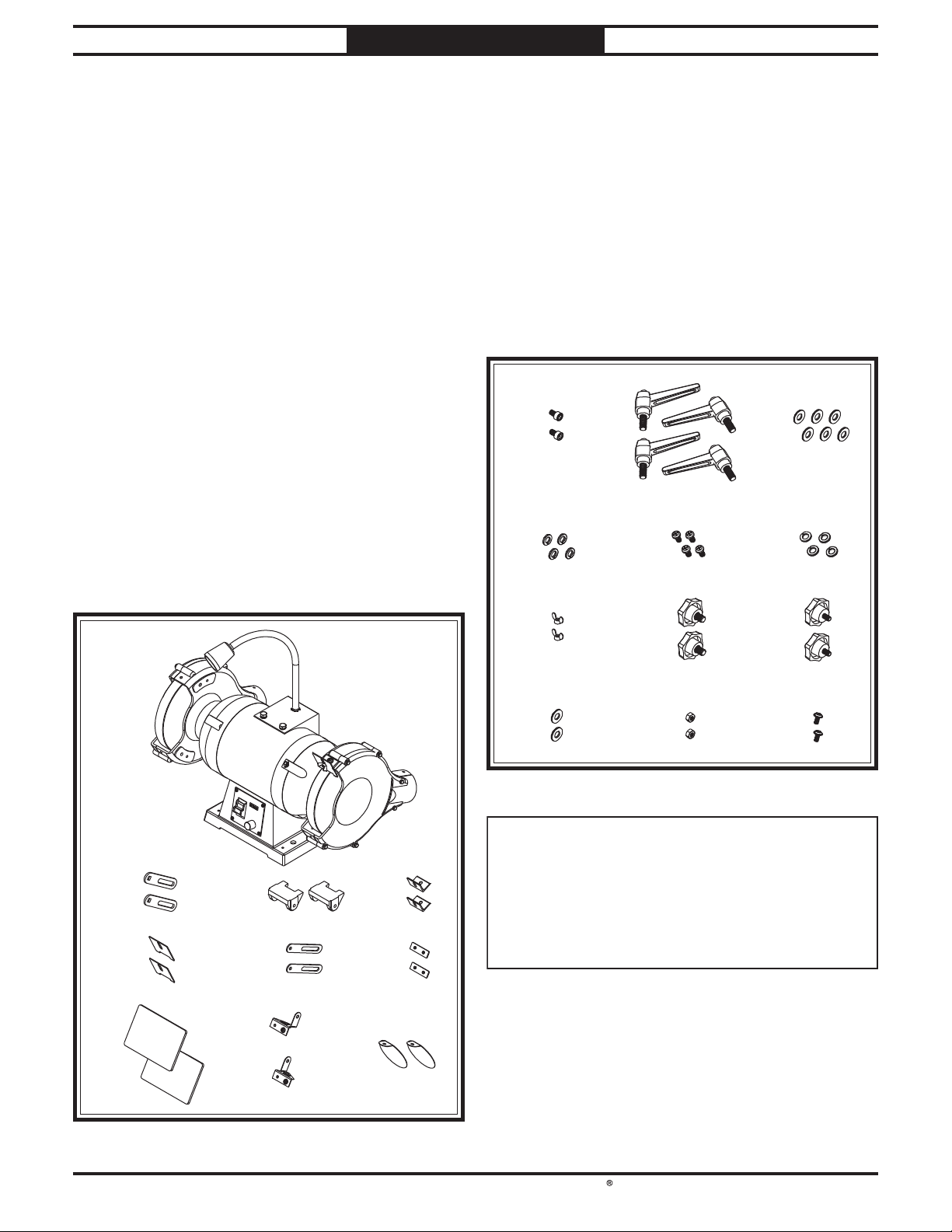
Inventory (Figure 6) Qty
A. Grinder ...........................................................1
B. Work Rest Supports....................................... 2
C. Work Rests .....................................................2
D. Spark Deflector Brackets...............................2
E. Spark Deflectors.............................................2
F. Eye Shield Supports ......................................2
G. Eye Shield Plates ........................................... 2
H. Eye Shields..................................................... 2
I. Left Eye Shield Bracket.................................1
J. Right Eye Shield Bracket ..............................1
K. Spark Hoods ...................................................2
Fasteners (Figure 7) Qty
L. Cap Screws 1/4"-20 x 3/8".................................2
M. Handles 5/16"-18 x 3/4"......................................4
N. Flat Washers 5/16"...........................................6
O. Lock Washers 5/16"..........................................4
P. Phillips Head Screws 1/4"-20 x 1/2".................4
Q. Lock Washers 1/4"...........................................4
R. Wing Nuts 1/4"-20............................................2
S. Knob Bolts 5/16"-18 x 1/2".................................2
T. Knob Bolts 1/4"-20 x 3/8"..................................2
U. Flat Washers 1/4"............................................2
V. Hex Nut 1/4"-20 ...............................................2
W. Flange Screws 10-24 x 3/8".............................6
Figure 7. Fasteners.
Figure 6. Main inventory.
A
BCD
E F G
J
I
H
K
L M
P
S
O
R
N
Q
WU V
T

South Bend Tools
For Machines Mfd. Since 1/21 Model SB1494
-13-
PREPARATION
The unpainted surfaces are coated
at the factory
with a heavy-duty rust preventative that
prevents corrosion during shipment and
storage.
The benefit of this rust preventative is that it
works very well. The downside is that it
can be
time-consuming
to thoroughly remove.
Be patient and do a careful job when
cleaning
and removing the rust preventative
. The time
you spend doing this will reward you with
smooth
-sliding parts and a better appreciation
for the proper care of
the unpainted surfaces.
Although there are many ways to successfully
remove the rust preventative, the
following
process works well in most situations
.
Before cleaning, gather the following:
• Disposable
rags
• Cleaner/degreaser
(certain citrus-based
degreasers work extremely well and they
have non-toxic fumes)
• Safety glasses & disposable gloves
Note:
Automotive degreasers, mineral spirits, or
WD•40 can be used to remove rust preventative.
Before using these products, though, test them
on an inconspicuous area of a painted surface to
make sure they will not damage it.
Basic steps for removing rust preventative:
1. Put on safety glasses and disposable gloves.
2. Coat all surfaces that have rust preventative
with a liberal amount of your cleaner or
degreaser and let them soak for a few
minutes.
3. Wipe off the surfaces. If your cleaner or
degreaser is effective, the rust preventative
will wipe off easily.
Note: To clean off thick coats of rust
preventative on flat surfaces, such as beds
or tables, use a PLASTIC paint scraper to
scrape off the majority of the coating before
wiping it off with your rag. (Do not use a
metal scraper or it may scratch the surface.)
4. Repeat Steps 2–3 as necessary until clean,
then coat all unpainted surfaces with a
quality metal protectant or light oil to
prevent rust.
GAS
Gasoline and petroleum
products have low flash
points and can explode
or cause fire if used for
cleaning. Avoid using these
products to remove rust
preventative.
Many cleaning solvents are
toxic if inhaled. Minimize
your risk by only using
these products in a well
ventilated area.
Avoid chlorine-based solvents, such as
acetone or brake parts cleaner that may
damage painted surfaces. Always follow the
manufacturer’s instructions when using any
type of cleaning product.
T23692—Orange Power Degreaser
A great product for removing the waxy shipping
grease from the non-painted parts of the
machine during clean up.
Cleaning & Protecting
Figure 8. T23692 Orange Power Degreaser.
-14-
For Machines Mfd. Since 1/21
South Bend Tools
Model SB1494 PREPARATION
Bench Mounting
The base of this machine has mounting holes
that allow it to be fastened to a workbench or
other mounting surface to prevent it from moving
during operation and causing accidental injury or
damage.
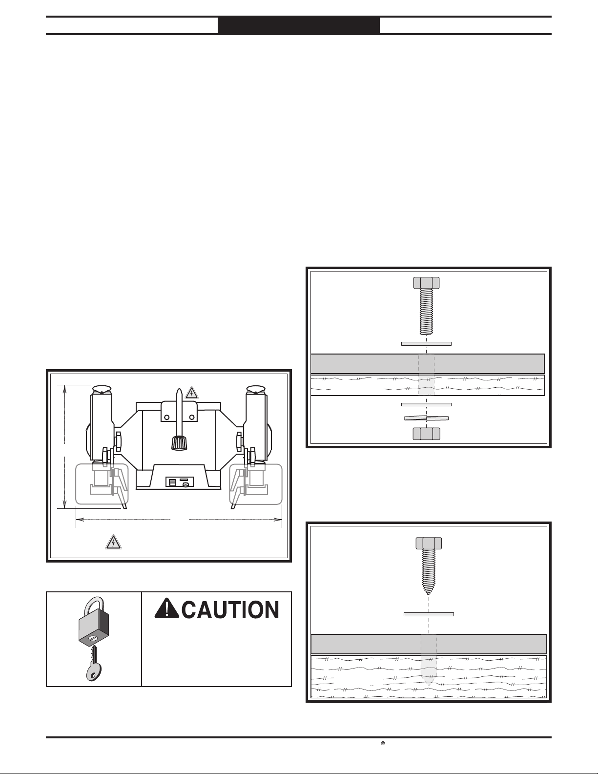
The strongest mounting option is a "Through
Mount" (see example below) where holes are
drilled all the way through the workbench—and
hex bolts, washers, and hex nuts are used to
secure the machine in place.
Figure 10. "Through Mount" setup.
Machine Base
Workbench
Hex Bolt
Flat Washer
Flat Washer
Lock Washer
Hex Nut
Another option is a "direct mount" (see example
below) where the machine is secured directly to
the workbench with lag screws and washers.
Machine Base
Workbench
Lag Screw
Flat Washer
Figure 11. "Direct Mount" setup.
Location
Weight Load
Refer to the Machine Specifications for the
weight of your machine. Make sure that the
surface upon which the machine is placed will
bear the weight of the machine, additional
equipment that may be installed on the machine,
and the heaviest workpiece that will be used.
Additionally, consider the weight of the operator
and any dynamic loading that may occur when
operating the machine.
Space Allocation
Consider the largest size of workpiece that will
be processed through this machine and provide
enough space around the machine for adequate
operator material handling or the installation
of auxiliary equipment. With permanent
installations, leave enough space around
the machine to open or remove doors/covers
as required by the maintenance and service
described in this manual.
Children or untrained
people may be seriously
injured by this machine.
Only install in an access
restricted location.
24"
17½"
= Electrical Connection
Figure 9. Working clearances.
Number of Mounting Holes .............................4
Dia. of Mounting Hardware Needed ...........1⁄2"

South Bend Tools
For Machines Mfd. Since 1/21 Model SB1494
-15-
PREPARATION
Assembly
The machine must be fully assembled before it
can be operated. Before beginning the assembly
process, refer to Required for Setup on Page
9and gather all listed items. To ensure the
assembly process goes smoothly, first clean any
parts that are covered or coated in heavy-duty
rust preventative (if applicable).
To assemble machine:
1. Attach (1) work rest support to right wheel
guard with (1) 5⁄16"-18 x 3⁄4" handle, 5⁄16" lock
washer, 5⁄16" flat washer, and 1⁄4"-20 x 3⁄8" cap
screw (see Figure 12).
Figure 12. Work rest support attached to right wheel
guard.
2. Attach (1) work rest to work rest support
from Step 1 with (1) 5⁄16"-18 x 3⁄4" handle,
5⁄16" lock washer, and 5⁄16" flat washer (see
Figure 13).
Figure 13. Right work rest installed.
Work Rest
Work Rest
Support
Work Rest
Support
Wheel
Guard
3. Repeat Steps 1–2to install left work rest.
Note:There should be no more than 1⁄8"
between work rests and grinding wheels.
IMPORTANT: Work rests will need to be
adjusted as grinding wheels wear down. A
fully worn grinding wheel could be dramati-
cally smaller in diameter than a new wheel.
4. Attach (1) spark deflector bracket to right
wheel guard with (1) 1⁄4"-20 x 1⁄2" Phillips
head screw, and 1⁄4" lock washer (see
Figure 14).
Figure 14. Spark deflector bracket attached to right
wheel guard.
Figure 15. Right spark deflector installed.
5. Attach (1) spark deflector to bracket from
Step 1 with (1) 1⁄4"-20 x 1⁄2" Phillips head
screw, 1⁄4" lock washer, and 1⁄4"-20 wing nut
(see Figure 15).
Spark
Deflector
Spark
Deflector
Bracket
Spark
Deflector
Bracket
-16 -
For Machines Mfd. Since 1/21
South Bend Tools
Model SB1494 PREPARATION
6. Repeat Steps 4–5to install left spark
def lector.
Note: There should be no more than 1⁄4"
between spark deflectors and grinding
wheels.
IMPORTANT: Spark deflectors will need to
be adjusted as grinding wheels wear down. A
fully worn grinding wheel could be dramati-
cally smaller in diameter than a new wheel.
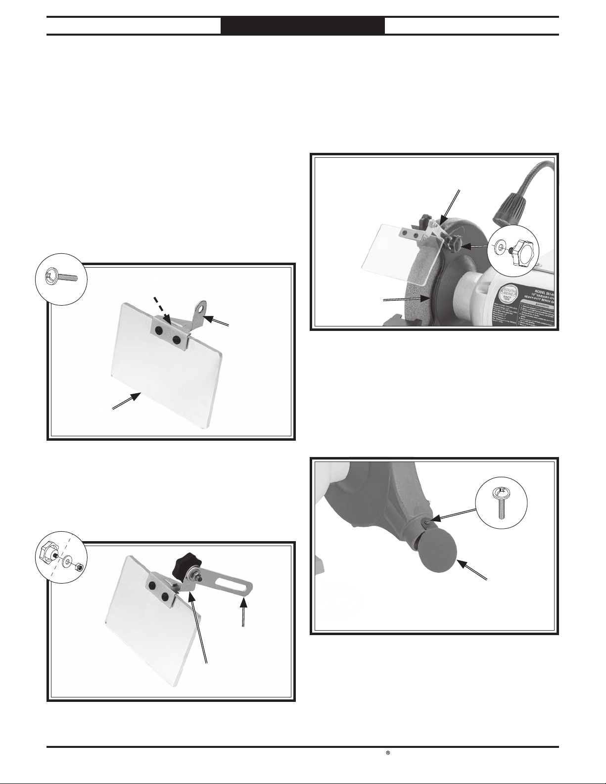
7. Attach (1) eye shield to each eye shield
bracket with (1) eye shield plate and (2) 10-24
x 3⁄8" flange screws (see Figure 16).
Figure 16. Eye shield attached to eye shield bracket
and plate.
Eye Shield
Eye Shield Plate
(Behind Eye Shield)
Eye Shield
Bracket
8. Attach each eye shield bracket to (1) eye
shield support with (1) 1⁄4"-20 x 3⁄8" knob
bolt, 1⁄4"flat washer, and 1⁄4"-20 hex nut (see
Figure 17).
Figure 1 7. Eye shield bracket attached to eye shield
support.
Eye Shield
Bracket
Eye Shield
Support
9. Attach left eye shield support to left wheel
guard with (1) 5⁄16"-18 x 1⁄2" knob bolt and 5⁄16"
flat washer (see Figure 18).
Note: Eye shield brackets are inscribed with
"L" for "left" and "R" for "right" to help distin-
guish between them.
Figure 18. Left eye shield support attached to left
wheel guard.
10. Repeat Step 9 with right eye shield support
to install right eye shield.
11. Attach (1) spark hood to back of each wheel
guard with (1) 10-24 x 3⁄8" flange screw (see
Figure 19).
Figure 19. Spark hood installed to wheel guard.
Spark
Hood
Left Eye Shield
Support
Left
Wheel Guard
x 2

South Bend Tools
For Machines Mfd. Since 1/21 Model SB1494
-17-
PREPARATION
Power Connection
Electrocution or fire
may occur if machine is
ungrounded, incorrectly
connected to power, or
connected to an undersized
circuit. Use a qualified
electrician to ensure a safe
power connection.
Once your machine is set up and assembled as
previously described in this manual, it is ready to
be connected to the power source.
Note About Extension Cords: Using an
incorrectly sized extension cord may decrease the
life of electrical components on your machine.
The Model SB1494 is prewired to operate on
110V power, but it can be converted for 220V
operation. 220V conversion consists of installing
the correct plug and a 220V LED work light, as
outlined in Full 220V Conversion.
Note: The 110V LED work light connections
will burn out with a 220V power supply, but
the light assembly can be removed altogether
instead of being replaced. Refer to Partial 220V
Conversion on Page 18 for instructions.
Wiring diagrams are provided in the back of this
manual showing the Model SB1494 wired for
both 110V and 220V. Refer to these diagrams on
Page 31 when following this procedure.
Full 220V Conversion
Items Needed Qty
Wire Cutter/Stripper.............................................1
NEMA 6-15 Plug ...................................................1
Electrical Tape ......................................As Needed
220V LED Work Light (Model T32731) ...............1
Wrench or Socket 1/2" ...........................................1
Open-Ended Wrench 3/4" ......................................1
To fully convert Model SB1494 to operate on
220V:
1. DISCONNECT MACHINE FROM POWER!
2. Cut off existing 5-15 plug.
3. Install 6-15 plug on power cord according to
plug manufacturer's instructions.
If plug manufacturer's instructions are not
available, NEMA standard 6-15 plug wiring
is provided on Page 32.
4. Remove (4) hex bolts and flat washers
securing work light mounting bracket to
grinder (see Figure 20).
x 4
Figure 20. Work light mounting bracket and securing
fasteners.
Work Light
Mounting Bracket
5. Loosen wire nuts indicated in Figure 21.
Ground
Neutral
Hot
MOTOR
110/220V
P
o
t
e
n
t
i
o
m
e
t
e
r
Circuit Board
BASE
Circuit Board
CROWN
AGE05010F12L
DC12V 0.15A
CX1812-WVF-CTRL-V1-4
Fuse
BUSSMAN
10A 250V
680uF 250V
S Cap
12V 15W
0.47uF K 310V
CX1603
680uF 250V
S Cap
JT3 JT2 JT1
JW JV JU
GND
TX+
TX−
RX−
RX+
VDD
CON1
CON2
Fan
To LED Light
To Plug
CX1918-VR-DIS-V1-1
15V
TX+
TX−
RX−
RX+
GND
Film Cap
23
2
3
ON/OFF Switch
JI-HONG J9301-1YT
125/250VAC 19/12A
(Prewired)
110 VAC
5-15 Plug
1
1
110VAC
LED Light
(Prewired)
LED LIGHT
MOUNTING BRACKET
WARNING!
!
!
SHOCK HAZARD!
Disconnect power
before working
on wiring.
Figure 21. 110V LED worklight wiring connections.
Loosen These
Wire Nuts

-18-
For Machines Mfd. Since 1/21
South Bend Tools
Model SB1494 PREPARATION
7. Insert 220V work light into mounting
bracket hole and secure with (1) 1/2"-18 hex
nut and 1/2" lock washer
8. Use wire nuts from Step 5 to connect 220V
work light wires shown in Figure 23. Twist
wire nuts onto their respective wires and
wrap them with electrical tape so they will
not come loose during operation.
Ground
Neutral
Hot
MOTOR
110/220V
P
o
t
e
n
t
i
o
m
e
t
e
r
Circuit Board
BASE
Circuit Board
CROWN
AGE05010F12L
DC12V 0.15A
CX1812-WVF-CTRL-V1-4
Fuse
BUSSMAN
10A 250V
680uF 250V
S Cap
12V 15W
0.47uF K 310V
CX1603
680uF 250V
S Cap
JT3 JT2 JT1
JW JV JU
GND
TX+
TX−
RX−
RX+
VDD
CON1
CON2
Fan
To LED Light
To Plug
CX1918-VR-DIS-V1-1
15V
TX+
TX−
RX−
RX+
GND
Film Cap
23
2
3
ON/OFF Switch
JI-HONG J9301-1YT
125/250VAC 19/12A
(Prewired)
110 VAC
5-15 Plug
1
1
110VAC
LED Light
(Prewired)
LED LIGHT
MOUNTING BRACKET
WARNING!
!
!
SHOCK HAZARD!
Disconnect power
before working
on wiring.
Figure 23. Grinder rewired to 220V work light.
Connect
Wires Here
9. Secure work light mounting bracket to
grinder with fasteners removed in Step 4.
Partial 220V Conversion
Items Needed Qty
Wire Cutter/Stripper.............................................1
NEMA 6-15 Plug ...................................................1
Electrical Tape ......................................As Needed
Wrench or Socket 1/2"............................................1
Phillips Head Screwdriver #2...............................1
To partially convert Model SB1494 to
operate on 220V:
1. Refer to Steps 1–4of Full 220V Conversion
on Page 17.
2. Remove (4) flange screws securing base plate
to grinder (see Figure 24).
x 4
Base Plate
Figure 24. Base plate and securing flange screws.
3. Loosen wire nuts and remove LED light
wires indicated in Figure 25.
Ground
Neutral
Hot
MOTOR
110/220V
P
o
t
e
n
t
i
o
m
e
t
e
r
Circuit Board
BASE
Circuit Board
CROWN
AGE05010F12L
DC12V 0.15A
CX1812-WVF-CTRL-V1-4
Fuse
BUSSMAN
10A 250V
680uF 250V
S Cap
12V 15W
0.47uF K 310V
CX1603
680uF 250V
S Cap
JT3 JT2 JT1
JW JV JU
GND
TX+
TX−
RX−
RX+
VDD
CON1
CON2
Fan
To LED Light
To Plug
CX1918-VR-DIS-V1-1
15V
TX+
TX−
RX−
RX+
GND
Film Cap
23
2
3
ON/OFF Switch
JI-HONG J9301-1YT
125/250VAC 19/12A
(Prewired)
110 VAC
5-15 Plug
1
1
110VAC
LED Light
(Prewired)
LED LIGHT
MOUNTING BRACKET
WARNING!
!
!
SHOCK HAZARD!
Disconnect power
before working
on wiring.
Figure 25. LED worklight wiring connections.
Remove
These Wires
Loosen These
Wire Nuts
6. Remove (1) hex nut and lock washer securing
110V work light to mounting bracket (see
Figure 22) and remove work light.
Figure 22. Work light and securing fasteners.
Table of contents
Other Southbend Grinder manuals


 Handling instructions")


