Southern Cross LGCY27/10 Series User manual

DIESEL ENGINE PORTABLE ROTARY SCREW AIR
COMPRESSOR INSTRUCTION
MANUA
L
Model: LGCY27/10&LGCY32/10SERIES

LGCY series Page 1
1
Publisher's Note
This manual describes installation safety precautions, each-system structure functions,
operation and maintenance methods of LGCY series air compressor manufactured by
Zhejiang Kaishan Compressor Co., Ltd.
The operator shall carefully read this manual and can operate and maintain the unit only after
fully understanding the structure, functions and safety precautions of each part.
Zhejiang Kaishan Compressor Co., Ltd. will continuously make improvement to the product.
The user shall note that the contents herein may be different from the actual conditions of
product after a period.
If this manual does not clearly describe any aspect on operation and use, you may contact our
agent or directly contact our After-sales Service Department according to the address
provided herein. They will help you to solve the problem.
Before the new version is published, the use and maintenance of LGCY series air compressor
shall be subject to this manual, and other material can be only used for reference.
If you find any problem in use, please timely feed back to us, so that we can carry out study
and modification.

Table of Contents
Publisher's Note ....................................................................................................................................... 1
Table of Contents ..................................................................................................................................... 1
Chapter I Equipment Overview and Safety Warning ................................................................................... 2
Chapter II Structure and Operating Principle .............................................................................................. 9
Chapter III Main Performance and Technical Parameters .......................................................................... 24
Chapter IV Installation and Commissioning (Adjustment)......................................................................... 25
Chapter V Use and Operation.................................................................................................................. 26
Chapter VI Common Faults Analysis and Elimination............................................................................... 30
Chapter VII Maintenance........................................................................................................................ 33
Chapter VIII Spare Parts......................................................................................................................... 36

LGCY Series Page 2
Chapter I Equipment Overview and Safety Warning
1 Equipment Overview
The LGCY series of air compressor is elaborately designed and manufactured by us for customers, mainly
powered by diesel engine, connected with the air compressor handpiece through coupling to generate air and
further drive pneumatic tools such as jack drill to operate and drill holes; its feature is to operate under the
outdoor environment without electricity.
Note: Only a trained and authorized person can operate the compressor. The operator shall carefully
read this manual and fully understand its contents before operation. Accidents, casualties and or death
may occur in the case of failure to follow the operation procedure and safety precautions herein.
Warning: Do not start the unit under unsafe condition; if a fault has occurred, do not try to start the
equipment. Instead, switch off the equipment and make evident identification to prevent incorrect
operation by others, the use of the “Lock Out Tag Out” safety process is recommended.
Hazard: Compressed air is hazardous. Competent suitably trained persons can only repair and
maintain the unit after ensuring the pressure in the compressor system has been released.
The installation use and maintenance of equipment must be in accordance with relevant laws, regulations and
standards.
Unless approved by us, do not modify the internal structure and control method of unit.
Carry out routine maintenance, carefully inspect the units every day, and check for leaks, lose components,
damage or improper adjustments. If there is any abnormality, the compressor may not be used until the faults
are rectified.
Personnel Protection:
Before installing and operating the equipment, all personnel shall be familiar with and follow the operation
procedure and specifications on personal protection equipment in local regulations, including but not limited
to eye, face, hearing and respiratory protection, limb protection equipment, protective clothing, protection
plate, electric shock protection equipment and noise protection equipment.
2 Safety Warning
2.1 Lifting
2.1.1 The equipment for lifting compressor shall be suitable and conform to local safety specifications.
2.1.2 Inspect the lifting frame, lifting ring crack and bolt and nut looseness before lifting the
compressor.
2.1.3 Remove or fix all loose parts that may fall off and fix the rotational parts such as door and pull
rod.
2.1.4 Tether the equipment with rope during lifting to prevent the equipment rotating after lifting.
2.1.5 Do not lift the equipment when environmental conditions increase the hazard such as strong or
unstable winds.

LGCY Series Page 3
2.1.6 The lifting height shall be appropriate.
2.1.7 The lifting acceleration and deceleration shall be in the allowable safe range.
2.1.8 Ensure that all personnel are clear of the danger area during the lift.
2.1.9 Ensure the bearing capacity of placement ground when selecting the site for placing the
compressor.
2.2 Traction and Parking (Trailer Mount Only)
2.2.1 Preparation before traction
A. Check whether the compressor draw bar, pull ring and trailer connector are secure and in good
conditions.
B. Ensure the trailer connector is connected securely.
C. Ensure the connector is fully connected and fastened.
D. Ensure the tire pressure and check whether the axle, fixed bolt and vehicle wheel are fastened.
E. Ensure all doors and tool box covers are tightened and locked.
F. Ensure no one is in the equipment before closing the door.
G. The brake equipment shall be pre-tightened appropriately according to the gradient before downhill
dragging.
2.2.2 Traction
A. Avoid dragging when the gradient is greater than 15º.
B. Follow the local specifications on road traffic safety.
C. Do not exceed the free steering angle for forward or reverse travel. Do not drag the equipment
barbarously.
D. Avoid obstacles such as pit and stone and soft road surface.
E. Do not drag the compressor at excessive speed.
F. Do not carry a person on the compressor.
G. Do not stand and travel between the compressor and trailer.
2.2.3 Compressor Parking
A. Place the compressor on the ground as flat as possible.
B. Check whether the parking road surface can bear the weight of compressor.
C. Select the wind direction when parking the compressor, so the exhaust air and heat discharged by the
diesel engine can be blown away to prevent cyclic inhalation, compressor air displacement drop,
overheat and diesel engine power dip, etc.
D. The parking site shall be provided with clean air and good ventilation conditions. ensuring sufficient
heat dissipation space, operation and maintenance space at the periphery.
E. Park the equipment at the shady place free from sunlight exposure in summer.
F. Set the brake.
G. Chock both sides of wheel and avoid displacement of compressor unit.
H. Set warning signs and/or warning lights (night) when parking on the road to prevent traffic accident.

LGCY Series Page 4
2.3 Pressure Hazard
A. The allowable maximum working pressure of pneumatic tool shall be higher than the rated discharge
pressure of compressor.
B. The pipe, valve and facilities shall have appropriate size and meet the requirements of working
pressure.
C. Do not apply external force on the compressor air outlet ball valve whilst under pressure.
D. When the air discharge hose is connected or removed, the compressor air supply ball valve shall be
closed. Before the compressor discharge hose is removed, the operator shall ensure the pressure in the
discharge hose has been fully released. Before pressurising any connected hose ensure that the open end
of the hose is securely fixed.
E. Refuel the compressor only when the compressor is not running, and the pressure is fully released.
F. Release the pressure before opening or removing any pressure components, fittings, filling points or
filters.
G. Do not play with or direct compressed air at yourself or any other person, serious injury including
death can result from such practices.
H. When the engine coolant is being checked slowly screw off the radiator cap to release the pressure
after it is cooled. Ensure the coolant is not boiling before fully unscrewing the radiator cap.
2.4 Fire Hazard and Explosion
A. When refuelling the compressor use a refuelling station. Otherwise, connect the compressor and
refuelling equipment to the ground together.
B. When the lubricating oil or other inflammables are spilled, clear them immediately.
C. After the compressor is shut down and cooled, isolate the compressor to check or add the lubricating
oil, engine oil or coolant.
D. No liquid including the coolant shall be accumulated on any part of unit outer cover nor any part of
internal & external surface in the unit. Clean it with liquid detergent. Remove the outer cover for
cleaning when necessary. Do not use combustible liquid cleaning agents.
E. Switch off the power before carrying out any maintenance and cleaning.
F. Keep all wires, power joints and pressure joints intact and clean. Immediately replace them in case of
any damage.
G. Care must be taken not to short circuit battery terminals or cables to the body / frame of the
compressor as this may cause an explosion or fire.
H. Do not weld or repair but replace the damaged oil tank and oil pipe as far as possible. Do not operate
the compressor if there is any engine oil or fuel oil leakage.
I. Before welding and repair, remove all acoustic insulating materials to protect against any damage due
to heat.
J. Prepare applicable extinguisher before repairing and operating the compressor.

LGCY Series Page 5
K. Ensure that the surrounding area is kept clear of loose debris, rubbish and other inflammable rubbish
near the compressor.
L. During maintenance activities open all doors to prevent combustible vapour / fumes from
accumulating.
M. Do not place the compressor near or under vegetation to prevent contact with hot exhaust gases and
or exhaust components.
N. The anti-freeze agent used for some anti-freeze systems contains flammable methyl alcohol. Keep
ventilated and isolate any open flame when using or adding such type of anti-freeze agent. Such type of
system or agent cannot be exposed in the environment with the temperature higher than 66℃. The
specific gravity of anti-freeze agent vapour is greater than the air. Do not store such type of product
where insufficient ventilation is available. Do not directly expose the anti-freeze agent or container
under the sunlight.
O. All flammable liquid shall be stored at a place far away from the working site. Get familiar with the
extinguisher position, type and using method. Check the conditions of fire extinguishing system.
2.5 Moving Components
A. Hands, arms, other body parts and clothing must stay clear of the cooling fan and other moving
components. Enclosure doors and panels must be securely fastened to ensure the safety of operators.
B. Do not operate the compressor after the protective cover of fan or other components is removed.
C. Wear appropriate personal protective equipment whilst operating this equipment particularly near hot
surfaces or moving components.
D. Close the door on the unit when the maintenance is not carried out.
E. Ensure no one is in the unit and all doors and panels are closed and in place prior start-up.
F. The following operations can be made only after shutdown: filling fuel oil, cooling liquid, lubricating
oil, replacing battery or diethyl ether tank, etc.
G. Disconnect the battery before carrying out any maintenance, to avoid accidental start-up of engine.
After disconnection, make a clear identification to prevent reconnection by others.
H. Keep the ground near the control component and unit clean, and timely clean the oil and water stain
to prevent slipping or fall-off.
2.6 Hot Surface and Sharp Angles
A. Do not contact hot oil, cooling liquid and hot surface. Please note not to touch the sharp angles.
B. Do not directly face the exhaust port of compressor and diesel engine with any part of your body.
C. Wear the protective article such as gloves, working clothes and helmet during operation or
maintenance.
D. First-aid kit shall be provided. The injured should be treated immediately. Do not ignore small
scratches and burns that may cause infection.

LGCY Series Page 6
2.7 Toxicity and Stimulating Substance
A. Do not use the compressor air for breathing.
B. Only operate the compressor outdoors or at a fully ventilated area.
C. When installing the compressor, take into account the air intake position and do not inhale exhaust air
or other toxic or corrosive substances.
D. It is not recommended that this compressor be operated indoors. If the unit is operating indoors, the
diesel engine exhaust shall be transferred to the outdoor area. The unit shall be parked based on the wind
direction to avoid the personnel and compressor from inhaling the diesel exhaust.
E. The fuel, lubricating oil and anti-freeze solution used for the unit shall be protected against skin
contact and swallow. If they are in contact with the skin, wash them off with soapy water. If swallowed
carelessly, treat the patient immediately.
F. Wear an acid-proof apron and a face mask when maintaining the battery. If the electrolyte splashes on
the skin or clothing, rinse immediately with plenty of water.
G. When inspecting the battery or adding anti-freezing agent, wear the appropriate personal protective
equipment according to safety requirements. When the compressor is started, keep the valve open. Do
not direct either discharge ports at operators or other persons.
H. If diethyl ether or anti-freeze agent is splashed into your eyes, rinse immediately with plenty of water
and immediately seek medical attention.
I. Do not store the diethyl ether or anti-freeze agent in or near the workshop.
J. Anti-freeze agent for airline antifreeze system contains methanol which is a toxic substance. Avoid
contact with skin and eyes. Avoid inhaling its volatile air. In case of accidental ingestion, the inhaler
shall lie down, covered with an eye protection article, and immediately ask the doctor for help.
K. The diethyl ether is poisonous. Ingestion can cause death. Avoid skin, eye contact or swallow.
2.8 Electric Shock
A. The unit, tool placing site and operator’s working site, etc. shall be at least 3 m away from the external AC
power sources.
B. The body, hand tools and other electrical conductors shall not contact exposed AC cables. When repairing
and adjusting these parts, stand on insulation objects and do not wet the soles.
C. Select a clean, dry and ventilated site during maintenance.
D. Keep away from the compressor when lightning strike occurs.
2.9 Accidental Winding
A. Close the door on the unit before starting up (to ensure no one is in the unit during start-up). If the
compressor is large enough and it is necessary to carry out maintenance in the unit indeed, other personnel shall
be told that someone is in the unit.

LGCY Series Page 7
2.10 Jump / Booster Start
A. The safety precautions in the previous sections of this manual shall be read carefully before jump start. Jump
start is only an emergency measure taken when the battery capacity of unit is insufficient.
B. The battery may contain hydrogen and there shall be no flames, sparks or other sources of ignition around
the unit.
C. The electrolyte in the battery is highly corrosive and toxic. It cannot be in contact with the eyes, skin or fiber
surface. Otherwise, it will cause personal injury or property damage. Wear an acid-proof apron and a face mask
when implementing the bridging start.
D. Remove the ventilation cover of the unit battery and note not to let dust or other debris fall into the battery.
E. If the electrolyte is not enough, it should be added as required.
F. It can only be powered by a vehicle with the same battery system as the unit (direct grounding). The supplied
voltage shall be the same and the capacity is sufficient. It cannot be powered by generator, welder or other DC
power supply to avoid accidents.
G. The used jumper cable shall be clean and the rated current of the wire should be greater than the starting
current.
H. Avoid accidental contact between wire terminal, wire clamp and other metal parts to prevent a fire due to
electric arc.
I. Generally, the positive pole of the battery is marked with the words "+" and "POS", and the negative pole is
marked with the words "-" and "NEG".
J. Start the machine according to the normal procedure. Note not to continuously start the compressor for a long
time.
K. After the unit diesel engine is warmed up and operated smoothly at idle speed, disassemble the negative-pole
wire terminal connected to the unit, and then remove the other end from the battery negative pole of power
supply vehicle, and then remove another jumper wire from the positive pole of the unit battery. Finally, remove
the positive terminal on the power supply vehicle. Carefully remove the cables. Recover the vent cap of the
battery
2.11 Safety Warning
12.1 Unlike general routine inspection, the maintenance work (including refueling) shall be carried out
the compressor is not operating.
12.2 Remove and maintain the pressure components only after the compressor is stopped and all
pressure is released.
12.3 Do not use the open flame light source to check the internal side of equipment or pressure
container.
12.4 During repair and maintenance, general components shall be covered to protect against dust, and
the exposed components shall be covered with clean duster cloth, paper or insulating tape to keep clean.
12.5 Do not carry out welding or heating operation near the fuel oil or lubricating oil system. Before

LGCY Series Page 8
similar operation, you must thoroughly clean the fuel and lubricating oil tank. For example, cleaning
with steam.
12.6 Protect the electrical, regulation components, air filter, etc. against moisture erosion, particularly
when cleaning with steam.
12.7 Do not use the flammable solvent when cleaning components. Please note that the cleaning liquid
may generate poisonous air.
12.8 After the repair work is completed, make sure that no tools, loose parts and wipes are left inside or
on the machine.
12.9 The moving components shall be supported firmly when repaired. Do not rely on the jack.
12.10 Replace the components with our original parts.
12.11 The maintenance and repair work of all mechanical equipment shall be recorded by the operator.
The number and reasons of repairs can help determine whether there are potential safety hazards.

LGCY Series Page 9
Chapter II Structure and Operating Principle
1 Structure
1.1 Equipment Structure (as shown in the figure)

LGCY Series Page 10
1.2 System flow (see Figure 1): main air circuit system, control air circuit system,
oil circuit system.
LGCY Series Page 11
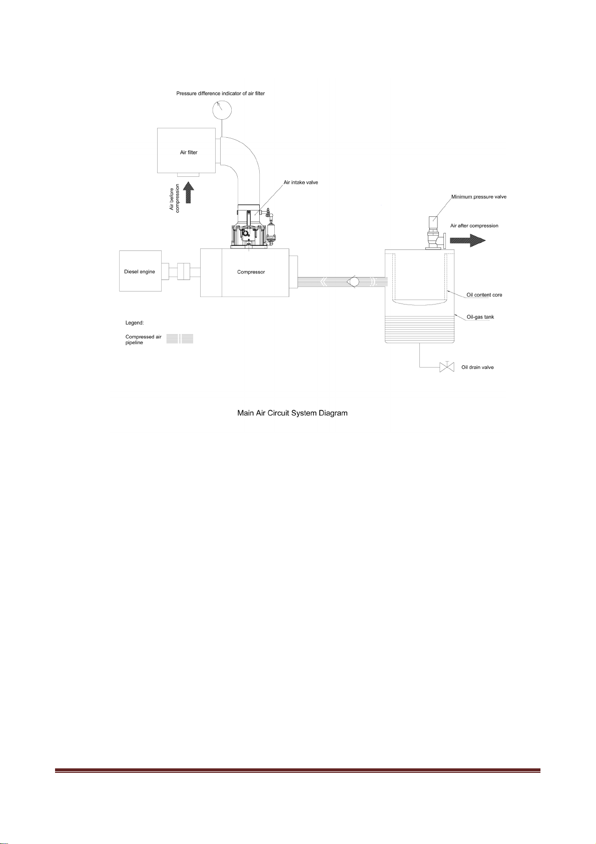
1.2.1 Main Air Circuit System:
Composition: composed of air filter, intake valve, screw compressor, oil-air separator (including oil
content core) and minimum pressure valve, etc.
Operating principle: After removed of dust and impurities by the air filter, the external air enters the
intake cavity of screw compressor through the air intake valve and is mixed with the injected lubricating
oil during compression. The compressed the air-oil mixture is discharged into the air-oil separator
(air-oil tank), and more than 99% of oil is separated. Then, after being further separated by the
secondary oil-air separator (oil content core), the clean compression air enters the use system through
the minimum pressure valve.
Function: for air compression.
A. Air filter
The air filter is a dry paper filter, and the filter paper has a pore size of about 10 um. Its main function is
to filter the dust in the air.
B. Air Intake Valve
The intake valve is disc type. Through the opening, half opening and closing of the disc, the adjustment
of the intake air amount (i.e., exhaust amount) can be realized, thereby achieving the purpose of energy
saving.
LGCY Series Page 12
C. Screw Compressor
As the rotor rotates, the size of the intertooth space formed by the female and male rotors changes to
complete the suction, compression and discharge of air. At the same time of compression, the
lubricating oil is also injected into the compression chamber due to the pressure difference and mixed
with the air and discharged to the oil separator together.
D. Oil-air separator
In order to reduce the oil content in the exhaust air (i.e., reducing fuel consumption) and recycle the
lubricating oil in the unit, an oil separator must be used. The oil and air mixture from the compressor
enter the primary oil separator (oil-air tank), and most of the lubricating oil is separated based on the
mechanical collision method. Then, the oil and air mixture with greatly reduced oil content enters the
secondary oil-air separator (oil content core) at a lower flow rate. The residual lubricating oil is further
separated through affinity coalescence method.
E. Minimum Pressure Valve
The clean, separated compressed air is sent to the use system through the minimum pressure valve. The
minimum pressure valve has the opening pressure of about 0.45Mpa and mainly has the following
functions:
a. Establish the required cycle pressure of lubricating oil preferentially during start to ensure the
lubrication of the equipment.
b. The oil-air tank can be opened only after its pressure exceeds 0.45Mpa to reduce the air flow rate of
oil content core. The oil content core can be protected against damage due to large pressure difference in
addition to ensuring the separation effect of oil content core.
c. Non-return function: When the pressure in the oil and air tank drops after stopping, the compressed
air in the pipeline shall be prevented from flowing back.
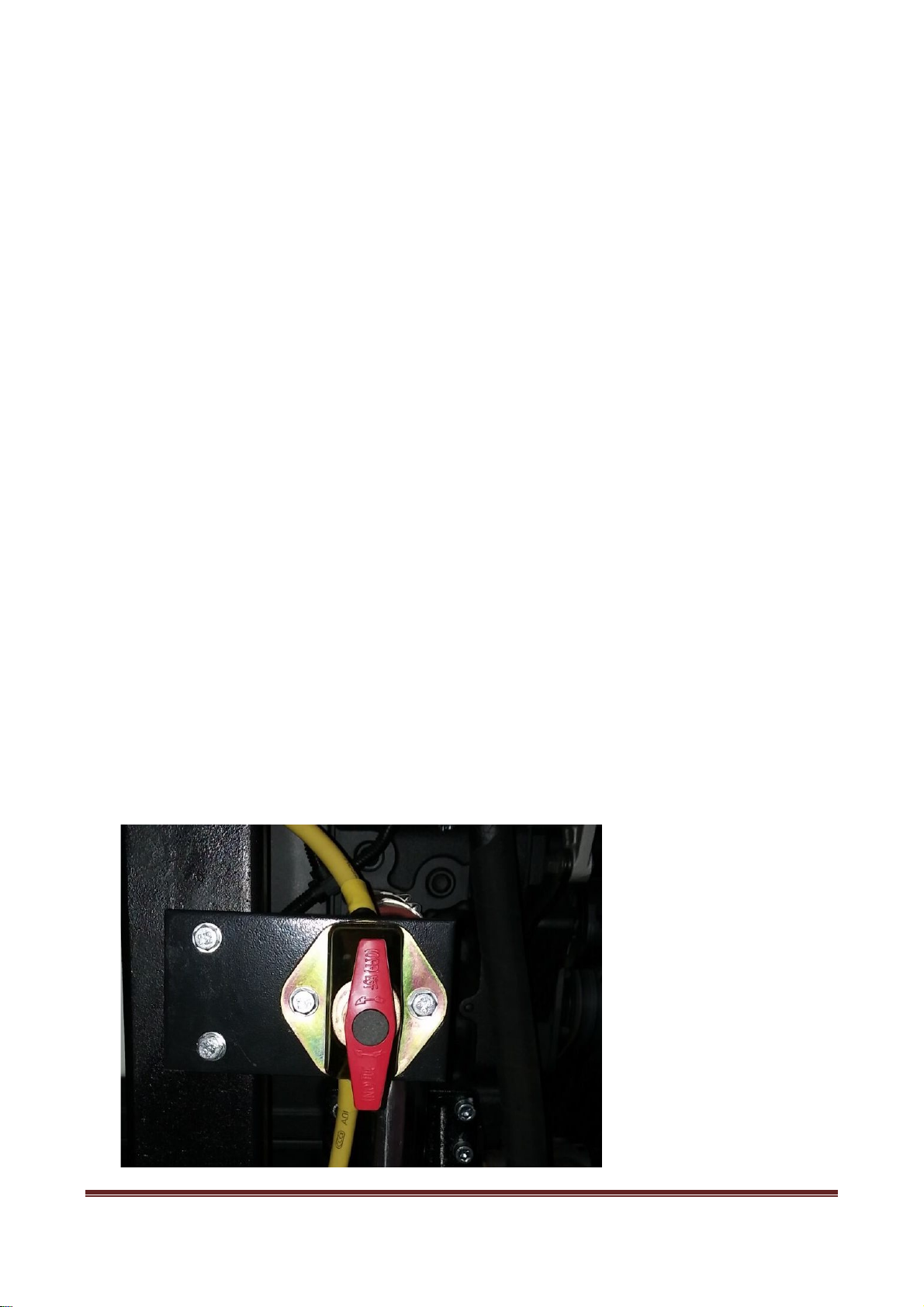
F. Power Switch`
For switching on or off the main power of circuit.

LGCY Series Page 13
1.2.2 Control Air Circuit System:
Composition: proportional valve (pressure regulator), air release valve, air intake valve servo cylinder
and safety valve;
Operating principle: After the start button is pressed (turning the LOAD/UNLOAD switching valve to
position 2 “- or UNLOAD” and driving the screw handpiece in the process of diesel engine start), the air
enters the handpiece through the air intake valve to quickly generate pressure. Then, the intake valve is
closed to make the internal air in the handpiece nearly become vacuum state and to start the light load
successfully; after successful start, the servo cylinder on the intake valve (opening pressure: 0.2Mpa) is
slowly opened in the process of pressure establishment due to increased system pressure. Another circuit
is opened by the internal integrated air release valve under the control of LOAD/UNLOAD switching
valve passage, to make the oil-air tank air and handpiece interconnected and reach internal circulating
state. The system is stabilized after its pressure gradually rises to about 0.45Mpa. After the temperature
of engine cooling liquid (water) temperature rises (idling time: 2-3 minutes), turn the LOAD/UNLOAD
switching valve to position 1 + or LOAD. Then, the equipment will enter the load (normal operation)
mode; when the pressure rises to the set operating pressure (i.e., rated pressure 1.0Mpa) of proportional
valve (i.e., pressure regulator), the proportional valve (i.e., pressure regulator) will operate to slowly
close the air intake valve based on the air consumption ; when the air consumption is sufficient or no air
is consumed (equivalent to closed state of ball valve), the proportional valve (i.e., pressure regulator)
will operate to fully close the air intake valve. The diesel engine speed changes with the pressure change
and is gradually reduced to the idle state.

LGCY Series Page 14
Rated pressure adjustment: The equipment is set as per the rated pressure of 1.0MPa before being
delivered. If the maximum pressure required for the user's air equipment is 1.0 MPa, the user can use it
directly after start-up, without resetting the working pressure of the pressure regulator by yourself; if the
maximum pressure required for some users’ air equipment is less than 1.0 MPa. For example, the
maximum pressure required for the user's air equipment is only 0.8MPa pressure. At this time, the user
needs to adjust the working pressure of the relevant proportional valve (i.e. pressure regulator). The
adjustment procedure is as follows:
Step I, turn the LOAD/UNLOAD switching valve to “- or UNLOAD” position. Start the equipment and
make it operate normally. Then, the LOAD/UNLOAD switching valve to “+ or LOAD” position.
Slowly turn down the air outlet valve of compressor with hand to increase the pressure to 0.8MPa;
Step II, loosen the locknut 2 on the proportional valve (i.e., pressure regulator). Rotate the regulating
screw 1 clockwise until the air is discharged from the air release hole 3 of proportional valve (i.e.,
pressure regulator);
Step III, re-lock the nut 2 on the proportional valve (i.e., pressure regulator).

LGCY Series Page 15
Function: for ensuring the compressor normally operates under the set rated pressure.
A. LOAD/UNLOAD switching valve
The LOAD/UNLOAD switching valve is manual and used to switch load/unload. Unload during startup
and before shutdown, and load during working time. The equipment full-automatically regulates the
operation relying on the proportional valve. Two-position and three-way switching valve has the
function of air release valve during shutdown.
B. Proportional valve
The proportional valve is a pressure regulating valve, which is a key component for pressure control. It
converts the working pressure (input pressure) into control pressure (output pressure), and the output
pressure decides the amount of expansion and contraction of two servo cylinders.
C. Air intake valve servo cylinder
The servo cylinder is the actuator. The air intake valve servo cylinder controls the opening degree of the
intake valve disc according to the output pressure of the pressure regulator, thereby controlling the
intake air amount.
D. Air release valve
The vent valve is installed behind the oil core and in front of the minimum pressure valve. It is also
controlled by the pressure regulator output pressure, and vents to the atmosphere in time to gradually
reduce the pressure in the oil-air tank.
E. Safety valve
The safety valve is a component that ensures the safe operation of the equipment and does not operate
under normal working conditions. If the safety valve continuously operates, the cause should be checked

LGCY Series Page 16
in time (such as failure of intake air regulation, malfunction of diesel engine throttle adjustment, etc.)
and promptly eliminated. For large displacement compressor, if the air consumption of system suddenly
decreases to zero, the pressure rise speed may exceed the speed of pneumatic adjustment, to open the
safety valve to release pressure.
The safety valve has been adjusted before delivery. Please do not adjust it arbitrarily.
The method for checking the safety valve is to gently pull the air release lever on the safety valve when
the compressor is fully loaded. If the safety valve can exhaust outward, it is considered as normal.
1.2.3 Oil Circuit System:
Composition: The oil circuit system is composed of oil cooler, oil filter, oil-air tank, oil content core
and thermostat valve.
Operating principle: For the oil circuit system without oil pump, the lubricating oil relies on the
pressure difference between the exhaust port of the compressor and the fuel injection port of the main
engine to maintain the flow in the circuit. When the equipment operates, the lubricating oil in the oil-air
tank enters the oil cooler under the action of differential pressure. After cooled and removed of
impurities and particles by the oil filter, most of lubricating oil is injected into the compression chamber
of compressor, and the remaining lubricating oil is distributed to the bearing and shaft seal, etc. to
function as lubrication, sealing, cooling and noise reduction. At last, all lubricating oil is discharged into
the oil-air tank with the compressed air to separate most of lubricating oil for recycling. A small amount
of lubricating oil separated by the oil content core is also brought back to the low-pressure position such
as air intake port.
Function: The oil is mainly used to seal the compressed air and to remove the heat generated during the
process of compressing the air.
A. Oil cooler

LGCY Series Page 17
The oil cooler cools the circulating lubricating oil. The fins of the oil cooler are easily covered by dust
to affect the cooling effect, which may cause stop due to exhaust air overtemperature. Therefore, it
should be purged and cleaned at an interval to ensure its cooling effect.
B. Oil filter
The oil filter is a paper filter whose function is to remove impurities in the oil, such as metal particles,
oil deteriorated substance, etc., to protect the normal operation of the bearing and the rotor. The
filtration accuracy is between 10μ and 15μ. The oil filter is a one-time consumable. If the oil filter is not
replaced in time, it may cause insufficient oil intake and the exhaust temperature rise at the handpiece,
which may cause shutdown. At the same time, insufficient oil may affect the service life of the main
engine bearing.
C. Oil-air Tank
Oil-air tank, also known as primary oil-air separator, separates oil from oil and air mixture based on the
mechanical collision method. An oil level indicator is installed at the tank side. A blowdown ball valve
is installed below the oil-air tank to eliminate the condensed water in the oil-air tank (The water is
coagulated at the bottom because it’s heavier than the oil). There is an oil filling port on the tank for
refuelling.
D. Oil Content Core
The oil core, also known as secondary oil-air separator, further separates the residual lubricating oil
based on the affinity coalescence method. The oil content core is made of multi-layer fine glass fiber.
The misty oil contained in the compressed air can be almost completely filtered through the oil content
core. The oil particle size can be controlled to be less than 0.1um and the oil content can be less than
5PPm. A small amount of lubricating oil separated by the oil core is concentrated in the groove at the
bottom of the oil core and is brought back to the low-pressure position of compressor such as air intake
port through the oil return check valve. Under normal operation, the oil core can be used for about
500-1000 working hours, but the quality of the lubricating oil and the surrounding environment have a
great impact on its service life. If the environmental pollution is very serious, you may consider
installing a front air filter. As for the selection of lubricating oil, it is necessary to use the special oil for
screw compressor recommended by us. Do not mix different grades of lubricating oil and use fake oil.
Generally, the oil content core damage can be judged by:
A. Checking whether the front and back pressure difference of oil content core exceeds 0.1Mpa with the
switching valve;
B. Checking whether the oil content in the air pipeline increases.
E. Thermostat valve
The equipment is equipped with a temperature control valve in front of the oil cooler. Its function is to
maintain the handpiece discharge temperature above the pressure dew point temperature to prevent the
water vapor in the air from being condensed in the oil-air tank to emulsify the lubricating oil. When the
equipment is turned on, the lubricating oil temperature is low. At this time, the temperature control valve
of the branch is opened, the main circuit is closed, and the oil directly enters the engine body without

LGCY Series Page 18
passing through the oil cooler. When the oil temperature rises to the lower limit (about 83 ° C) of the
temperature control valve opening temperature, the temperature control valve is gradually opened to the
passage of the oil cooler for cooling. Usually, the passage from the temperature control valve to the oil
cooler is fully opened when the oil temperature rises to about 86 ° C. At this moment, the oil will enter
the engine body after being cooled by the oil cooler.
2 Operating Principle
2.1 Air Intake Process:
The air intake of screw compressor is adjusted only by opening and closing an intake air throttle valve.
The intertooth space of male and female rotors is the largest when they rotate to the opening of
enclosure air intake end wall. At this moment, the intertooth space below the rotor is connected with the
free air of air inlet port. The air in the intertooth space is fully discharged during air exhaust, so the
intertooth space is at vacuum state after air exhaust. When the rotors rotate to the air inlet, the external
air will be absorbed and flows into the intertooth space of male and female rotors along the axial
direction. When the whole intertooth space is filled with air, the air inlet side end face of rotor will be
away from the air inlet of enclosure, and the air in the intertooth space will be sealed. The process is
called “air inlet process”.
2.2 Sealing and Conveying Process:
When the air intake is finished, the tooth peak of male and female rotors will be sealed with enclosure.
The air in the intertooth space does not flow externally, and this process is called “sealing process”.
Both rotors continue to rotate. Its tooth peak is coinciding with intertooth space at the air intake end, and
the coinciding surface gradually moves to the exhaust end. This process is called “conveying process”.
2.3 Compression and Oil Injection Process:
In the process of conveying, the mating surface gradually moves to the exhaust end, i.e., the intertooth
space between the mating surface and exhaust port is gradually reduced, the air in the intertooth space is
gradually compressed, and pressure is gradually increased, i.e., “compression process”. While
compression is carried out, the lubricating oil is also injected into the compression chamber and mixed
with the air.
The oil injection mainly has four functions:
A. Lubrication: Lubricating oil can form an oil film between the rotors, avoiding contact between the
rotors and reducing friction;
B. Cooling: Since the lubricating oil absorbs a large amount of compression heat, the compression
process is close to isothermal compression, which reduces the specific power of the compressor;
C. Sealing: The oil film produced by the lubricating oil can seal the compressed air and improve the
volumetric efficiency of the compressor;
D. Noise reduction: reducing the noise generated by high frequency compression
2.4 Exhaust Process:
When the exhaust port end face of the rotor is connected with the enclosure (the pressure of the
This manual suits for next models
4
Table of contents
Popular Air Compressor manuals by other brands


Dorin innovation
Dorin innovation 2Q-80VS Series Operating instruction

Truper
Truper COMP-120LV manual

Atmos
Atmos PDK 33 Series Operation and Maintenance Handbook

RTI
RTI SKL1200 Instructions and operating manual

ISANTA
ISANTA Senco AC19306BL operating instructions

Gem Audio Labs
Gem Audio Labs Compactor user manual


