Atmos PDK 33 Series Manual

Operation and maintenance handbook
ATMOS
Portable screw compressor
ATMOS PDK 33
ATMOS Chrást s.r.o.; Plze ˇ
nská 149; 330 03 Chrást; Czech Republic
Tel.:
Fax.:
+420 / 377 860 - 181
+420 / 377 860 - 111
+420 / 377 745 247
+420 / 377 945 379
At 2020/N Version
X.11.2016


CONTENTS
General description ..................................................... 2
Guarantee conditions . . . . . . . . . . . . . . . . . . . . . . . . . . . . . . . . . . . . . . . . . . . . . . . . . 2
Drawings, diagrams, descriptions and explanations .................................. 4
Dimensions....................................................... 4
Safetyregulations ................................................... 5
Technical parameters . . . . . . . . . . . . . . . . . . . . . . . . . . . . . . . . . . . . . . . . . . . . . . . . . 6
Safetysystem ..................................................... 7
Functionaldiagram................................................... 9
Description of the workstation(s) ............................................. 10
Description of the intended use .............................................. 11
Warnings concerning ways in which the machinery must not be used ........................ 12
Assembly, installation and connection instructions .................................. 13
Instructions relating to installation and assembly for reducing noise or vibration ................. 14
Instructions for the putting into service and usage of the machinery ......................... 15
Commissioning..................................................... 15
Beforestarting ..................................................... 15
Starting the machine . . . . . . . . . . . . . . . . . . . . . . . . . . . . . . . . . . . . . . . . . . . . . . . . . . 17
Stopping the machine . . . . . . . . . . . . . . . . . . . . . . . . . . . . . . . . . . . . . . . . . . . . . . . . . 18
Emergency shut-down . . . . . . . . . . . . . . . . . . . . . . . . . . . . . . . . . . . . . . . . . . . . . . . . . 19
Re-starting after an emergency shut-down . . . . . . . . . . . . . . . . . . . . . . . . . . . . . . . . . . . . . . 19
Machinemonitoring .................................................. 19
Operation in hard climatic conditions . . . . . . . . . . . . . . . . . . . . . . . . . . . . . . . . . . . . . . . . . 20
Information about the residual risks ........................................... 21
Instructions on the protective measures ......................................... 22
Battery........................................................ 22
Essential characteristics of tools ............................................. 23
The conditions in which the machinery meets the requirement of stability ..................... 24
Parking ......................................................... 24
Instructions with a view to ensuring that transport, handling and storage operations can be made safely . . . 25
Machinetransport ................................................... 25
Coupling the tow bar with suspension eye . . . . . . . . . . . . . . . . . . . . . . . . . . . . . . . . . . . . . . 25
Uncoupling the tow bar with suspension eye . . . . . . . . . . . . . . . . . . . . . . . . . . . . . . . . . . . . . 25
Coupling the tow bar with ISO 50 suspension . . . . . . . . . . . . . . . . . . . . . . . . . . . . . . . . . . . . 25
Uncoupling the tow bar with ISO 50 suspension . . . . . . . . . . . . . . . . . . . . . . . . . . . . . . . . . . . 26
Long term storage preparation . . . . . . . . . . . . . . . . . . . . . . . . . . . . . . . . . . . . . . . . . . . . . 26
1 At 2020/N
X.11.2016

Decommissioning ................................................... 27
Operating method to be followed in the event of accident or breakdown ...................... 28
Troubleshooting .................................................... 28
Emergency shut-down . . . . . . . . . . . . . . . . . . . . . . . . . . . . . . . . . . . . . . . . . . . . . . . . . 29
Description of the adjustment and maintenance operations .............................. 30
Wasteproducts..................................................... 30
Exchange of suspension equipment . . . . . . . . . . . . . . . . . . . . . . . . . . . . . . . . . . . . . . . . . . 30
Oilscavengeline.................................................... 31
Compressor oil filter . . . . . . . . . . . . . . . . . . . . . . . . . . . . . . . . . . . . . . . . . . . . . . . . . . 31
Assembly........................................................ 31
Oilseparatorinsert................................................... 31
Oilandwatercooler .................................................. 32
Compressordrive ................................................... 32
Alternatorbelt ..................................................... 32
Airfilter ......................................................... 33
Ventilation ....................................................... 33
Coolingfan....................................................... 33
Fuelsystem....................................................... 33
Fuelfilter ........................................................ 34
Fuel filter water separator (if installed) . . . . . . . . . . . . . . . . . . . . . . . . . . . . . . . . . . . . . . . . 34
Hoses.......................................................... 34
Electricalsystem.................................................... 34
Battery ......................................................... 35
Additional lubricator (if installed) . . . . . . . . . . . . . . . . . . . . . . . . . . . . . . . . . . . . . . . . . . . . 35
Pressuresystem .................................................... 35
Compressoroil..................................................... 35
Compressor oil specification . . . . . . . . . . . . . . . . . . . . . . . . . . . . . . . . . . . . . . . . . . . . . . 35
Speed and pressure control adjustment . . . . . . . . . . . . . . . . . . . . . . . . . . . . . . . . . . . . . . . . 36
Engine ......................................................... 36
Lubrication ....................................................... 36
Engineoil........................................................ 36
Engine oil specification . . . . . . . . . . . . . . . . . . . . . . . . . . . . . . . . . . . . . . . . . . . . . . . . . 37
Engineoilfilter ..................................................... 37
Inspection of the alternator belt tension . . . . . . . . . . . . . . . . . . . . . . . . . . . . . . . . . . . . . . . . 37
Running gear / wheels . . . . . . . . . . . . . . . . . . . . . . . . . . . . . . . . . . . . . . . . . . . . . . . . . 37
Wheelbearings..................................................... 37
Tyrespressure..................................................... 37
At 2020/N
X.11.2016
2

Brakes ......................................................... 37
Wheel brake adjustment . . . . . . . . . . . . . . . . . . . . . . . . . . . . . . . . . . . . . . . . . . . . . . . . 37
Adjusting the overrun braking system (Knott) . . . . . . . . . . . . . . . . . . . . . . . . . . . . . . . . . . . . . 37
Tighteningtorques................................................... 40
Instructions designed to enable adjustment and maintenance ............................ 41
Maintenance schedule . . . . . . . . . . . . . . . . . . . . . . . . . . . . . . . . . . . . . . . . . . . . . . . . . 41
Notice for maintenance . . . . . . . . . . . . . . . . . . . . . . . . . . . . . . . . . . . . . . . . . . . . . . . . 42
Maintenance ...................................................... 43
Beforemaintenance .................................................. 43
Minimal pressure valve . . . . . . . . . . . . . . . . . . . . . . . . . . . . . . . . . . . . . . . . . . . . . . . . . 43
Before removing of covers . . . . . . . . . . . . . . . . . . . . . . . . . . . . . . . . . . . . . . . . . . . . . . . 44
Maintenance on a running machine . . . . . . . . . . . . . . . . . . . . . . . . . . . . . . . . . . . . . . . . . . 44
Maintenance completion . . . . . . . . . . . . . . . . . . . . . . . . . . . . . . . . . . . . . . . . . . . . . . . . 44
Specifications of the spare parts ............................................. 45
Airborne noise emissions ................................................. 46
Non-ionising radiation ................................................... 47
3 At 2020/N
X.11.2016

GENERAL DESCRIPTION
Contents of this Operation and maintenance handbook are property of ATMOS Chrást company. This handbook is altered
and updated regularly for each production series and it may not be copied without written permission.
The producer does not assume responsibility for errors occurring from this translation.
This Handbook contains all information necessary for routine operation and maintenance of the machine. More detailed
information and procedures for larger repairs are not included in this Handbook but they are available at authorized service
partners of ATMOS Chrást company.
There may appear minor inconsistencies between the Handbook and the actual machine due to improvements of the
machine. Ask your dealer if you have any questions or problems.
The machine design complies with relevant EU regulations. This CE Declaration of conformity is losing its validity in case of
any not-approved modification of individual machine parts and components.
All parts, accessories, piping, hoses and connections through which the compressed air flows should be
∙of guaranteed quality and approved by the manufacturer for intended use,
∙approved for the nominal pressure level at least equal to machine maximum operation pressure,
∙usable in contact with compressor oil and coolant,
∙delivered together with the Handbook for installation and safe operation of the machine.
You will be provided with all details concerning suitability of individual parts use by selling and servicing centres of ATMOS
Chrást company.
The use of other than original spare parts, fluids and lubricants given in ATMOS Spare Parts Catalogue could lead to the
situation, for which ATMOS Chrást company cannot bear any responsibility. In such a case ATMOS Chrást company does
not take any responsibility for potential damage.
Read the Handbook carefully before operating the machine to fully understand its operation and maintenance requirements.
Guarantee the Operation and maintenance handbook is always at disposal directly by the machine.
Guarantee the maintenance personnel are always professionally trained and acquainted with instructions for operation and
maintenance.
Make sure the operating personnel is acquainted with all safety signs and instructions for machine operation before putting it
into operation or under maintenance.
Make sure all protective covers are installed and shut before putting the machine into operation.
A weekly visual check must be made on all fasteners/fixing screws securing mechanical parts. Notably, safety-related parts
such as a coupling hitch, drawbar components, road-wheels, and a lifting bail should be checked for absolute security.
All components which are loose, damaged or out of order must be repaired without delay.
GUARANTEE CONDITIONS
The manufacturer or its authorized service centre provides all guarantee and after-guarantee service.
If necessary, please contact the manufacturer or its authorized service centre where you will be provided with all necessary
information and recommendations.
Guarantee does not cover
∙
damage caused by incompetent operation and maintenance carried out in contrast with instructions in the Operation
and Maintenance Handbook,
∙damage caused by incompetent transport, manipulation (car accident) and storage,
∙damage caused by the machine operation in extremely aggressive surroundings,
∙consumable materials (filter and separator inserts, V-belts, etc.),
At 2020/N
X.11.2016
4

∙air end damage caused by corrosion or oil degradation influenced by omission of required inspections.
Guarantee is void
∙if filter inserts, separator inserts and other materials have not been replaced in intervals prescribed in the Handbook,
∙if the machine has been used for other purposes than those defined in the Handbook,
∙if damage has been caused by improper location of the machine in relation to cooling air supply and drain,
∙if other than prescribed fuels and oils have been used,
∙if other than original spare parts have been used,
∙if seals have been damaged,
∙
if the Service Booklet of the machine has not been presented to service engineers during a guarantee inspection or if
prescribed operations have not been logged to the Handbook,
∙if the machine breakdown has not been caused by a defect due to workmanship,
∙if there has been and intervention carried out on the machine construction,
∙if the machine has been repaired by other subjects than the manufacturer or its authorised service centre,
∙
if the machine has been handed over another owner without a technical inspection carried out by the manufacturer or
its authorised service centre,
∙
if prescribed guarantee inspections have not been carried out on time and have not been logged to this Service Booklet
with a coupon sent to the manufacturer,
∙if a claim has not been lodged in writing at the latest on the 10th day following the day a defect occurred,
∙if damage has been caused by a third person because of insufficient safety precautions,
∙
if the machine has not been put into operation, operating personnel have not been trained by the manufacturer’s
authorized service centre and this has not been logged to the Service Booklet,
∙if the registration card has not been filled in.
5 At 2020/N
X.11.2016

DRAWINGS, DIAGRAMS, DESCRIPTIONS AND EXPLANATIONS
DIMENSIONS
Dimension [mm] PDK 33 Dimension [mm] PDK 33
a750 j1565
b2395 k200
c2530 m1485
d3350 n1085
e430 o1280
f845 p1295
g851 r2485
h1265 s3235
i92
At 2020/N
X.11.2016
6

SAFETY REGULATIONS
THIS TYPE OF MACHINE IS INTENDED FOR OUTSIDE OF EU EXPORT ONLY.
Do not start!
Read operation and
maintenance manual before
start!
Attention!
Hot surface!
Attention!
Read operation and
maintenance manual before
starting service work!
Attention!
Do not stand on cocks and
other parts of the pressure
system!
Attention!
Do not operate the
compressor while door or
covers are open!
Attention!
Do not open the output cock
before air hoses are
connected!
Attention!
Hot gases!
Attention!
Pressure!
DIESEL
Fuel tanking
T ída / Class
API CH –4 -
ACEA E5
Motor oil filling
VDL 46
Compressor oil filling Coolant filling
Lifting point Anchoring point
7 At 2020/N
X.11.2016

TECHNICAL PARAMETERS
Compressor PDK 33-7 PDK 33-10 PDK 33-12
Air end B 100
Nominal capacity [m3·min–1] 5,0 3,8 3,2
Nominal overpressure [bar] 7,0 10,0 12,0
Safety valve setting [bar] 10,0 12,5 14,5
Ambient temperature [∘C] –10 ÷50
Max. outlet temperature [∘C] 110
Cooling system oil injection
Compressor oil filling volume [l] 7,2 7,2 7,2
Transmission oil filling vol. [l] - - -
Max. oil system temperature [∘C] 110,0 110,0 110,0
Max. oil system overpressure [bar] 8,6 11,6 13,5
Outlet cocks 2x G 3/4“
(KAG3/4“)
2x G 3/4“
(KAG3/4“)
2x G 3/4“
(KAG3/4“)
Engine PDK 33
Type/Model Kubota V1505-T
Cylinders 4
Load speed [min–1] 3000
Idle speed [min–1] 1500 ±50
Oil filling vol. [l] 6,7
Fuel tank vol. [l] 70,0
Coolant filling vol. [l] 4,0
Battery [V / Ah] 12 / 44
Noise emissions PDK 33
Sound power level LWA [dB(A)/pW] 98
Sound pressure level LpA
[dB(A)/20
𝜇Pa
]
78
Undercarriage (braked/unbraked) PDK 33
Type/Model Knott
Max. transport velocity* [km/h] 80
Total mass [kg] 750
Max. mass on axle [kg] 750
Max. mass on suspension [kg] 75
At 2020/N
X.11.2016
8

* Recommended transport velocity PDK 33
Max. design velocity [km/h] 80
Common roads [km/h] 80
Gravel roads [km/h] 50
Dirty tracks, etc. [km/h] 30
Ground [km/h] 10
Wheels and tyres PDK 33
Wheel discs 4.5J x 13 - 100x4
Tyres 155 R13 (155/80 R13)
Tyre pressure [kPa/bar] 250 / 2.5
SAFETY SYSTEM
Consists of:
∙low engine oil pressure switch,
∙high air end discharge temperature switch,
∙high engine coolant temperature switch,
∙alternator / drive belt failure circuit.
Low engine oil pressure switch
At three month intervals, test the engine oil pressure switch circuit as follows:
∙Start the machine.
∙Run the machine at idle speed.
∙
Disconnect the switch connector. Short-circuit contacts in the connector. The machine should shut down (after 2
second delay).
At twelve month intervals, test the engine oil pressure switch circuit as follows:
∙Remove the switch from the machine.
∙Connect the switch to an independent low pressure supply (either air or oil).
∙The switch should be switch offat 1.0 bar.
∙Reinstall the switch.
Temperature switch(es)
At three month intervals, test the temperature switch circuit(s) as follows:
∙Start the machine.
∙Run the machine at idle speed.
∙
Disconnect the switch connectors one by one. Short-circuit contacts in the connector. The machine should shut down
(after 2 second delay).
∙Reconnect the switches.
High air end discharge temperature switch(es)
At twelve month intervals, test the air end discharge temperature switch(es) by removing it (them) from the machine and
immersing in a bath of heated oil. The switch should be switch offat 110 ±5∘C. Reinstall the switch(es).
High engine coolant temperature switch
At twelve month intervals, test the engine coolant temperature switch removing it from the machine and immersing in a bath
of heated oil. The switch should be switch offat 110 ±3∘C Reinstall the switch.
9 At 2020/N
X.11.2016

Alternator / drive belt failure circuit
Test the circuit before each machine start as follows:
1. Turn the key to ON position and check that the recharge indicator is on.
2. Complete the machine starting sequence.
3. The recharge indicator should switch off.
At 2020/N
X.11.2016
10

FUNCTIONAL DIAGRAM
Explanatory
notes
1 air outlet 6 air end
2 nozzle / min. pres. valve 7 engine
3 manometer 8 oil cooler
4 separator tank 9 oil filter
5 safety valve 10 thermostat
oil
air
11 At 2020/N
X.11.2016

DESCRIPTION OF THE WORKSTATION(S)
Does not apply.
At 2020/N
X.11.2016
12

DESCRIPTION OF THE INTENDED USE
Compressed air can be dangerous when used improperly! Before any operation, maintenance or machine repairs - the
pressure system should be completely empty (free from over-pressure). Besides this, the machine shall be secured against
accidental starting.
Guarantee the machine will be operated on nominal pressure only and the compressor operating personnel are acquainted
with this instruction. Pressure level of compressed air equipment connected to the machine must be at least the same as the
machine nominal pressure level.
Warning
Under no circumstances compressed air is allowed to be used for direct human respiration!
Warning
Compressed air can cause serious injury or death. Relieve overpressure before removing filler plugs/caps, fit-
tings or covers.
Warning
Residual air pressure in the air system can cause serious injury or death. Always carefully vent the air supply
line to tools or cocks before any maintenance.
Output air contains a small amount of compressor oil. For this reason it is necessary to verify the compatibility of all used
equipment connected to the compressed air source.
If compressed air flows into the closed space, it is necessary to provide cooling of the air.
All personnel should always wear proper protective clothes when working with compressed air.
All pressure loaded parts including the pressure hoses should be tested regularly. No signs of damage should be observed
and all parts should be used in conformance with instructions for their use and/or for their intended purpose.
Avoid contact with compressed air.
The safety valve on the oil separator should be tested regularly according to given instructions.
When the machine is stopped, compressed air can flow back into the compressor system from devices or systems
downstream of the machine, unless the service valve is closed. Install a back pressure valve at the machine outlet cocks to
avoid reverse flow in the event of an unexpected shut-down when the outlet cocks are open.
Disconnected air hoses whip and can cause serious injury or death. Always attach a safety flow restrictor to each hose
according to safety rules.
The supposed ways of the machine use are presented below. If the machine should be used in an unusual way or in an
unusual surroundings, please contact the manufacturer.
This machine has been designed and supplied for use under following conditions only:
∙compressing the usual air that does not contain any additional gases, vapours or additives,
∙the machine will be operated at temperatures shown in chapter Technical parameters on page 6 ,
∙the machine will be operated in conformance with this Operation and maintenance handbook.,
∙the generator will be operated up to nominal current and voltage (when the machine is equipped with a generator).
13 At 2020/N
X.11.2016

WARNINGS CONCERNING WAYS IN WHICH THE MACHINERY MUST NOT BE
USED
Due to machine design it is not possible to use the machine at locations where danger of explosion exists. If the machine is
to be operated in such places, all local rules, standards and regulations must be fulfilled by adding of suitable supplementary
devices, such as gas detectors, combustion products removal, safety valves, etc. to eliminate all risks.
Warning
Air discharged from this machine may contain carbon monoxide or other contaminants which will cause serious
injury or death. Do not breathe this air.
The machine produces loud noise with its doors open or a service valve vented. Extended exposure to loud noise can cause
hearing loss. Always wear hearing protectors when the doors are open or the service valve is vented.
Warning
Never inspect or service the machine without previous disconnection of battery cables to prevent accidental
starting of the machine.
Do not use petroleum products (solvents or fuels) under high pressure as this can penetrate the skin and result in serious
illness. Wear eye protection while cleaning the machine with compressed air to prevent eye injury.
Rotating fan blades can cause serious injury. Do not operate the machine without a fan guard installed.
Avoid contact with hot surfaces (an engine exhaust manifold and pipping, an air receiver and air discharge pipping, etc.).
Never use volatile substances (e. g. ether) as a starting aid.
Never operate the machine with guards, covers or screens removed. Keep hands, hair, clothing, tools, etc. away from
moving parts.
The machine is not allowed to be used :
∙as a direct supply of pressurized air for respiration purposes,
∙for indirect human consumption without suitable air filtration and purity check,
∙out of temperature range specified in the general information section of this handbook,
∙in surroundings containing explosive gases or vapours,
∙in areas with no reliable device for combustion products removal,
∙with accessories, components, lubricants and coolants not recommended by ATMOS Chrást company,
∙for operation with not functional safety or control elements of without these elements.
At 2020/N
X.11.2016
14

ASSEMBLY, INSTALLATION AND CONNECTION INSTRUCTIONS
If more than one compressor are connected to the pneumatic equipment at the same time, every machine should be
equipped with a non-return flap valve to avoid back air streaming through the output cocks into the machine.
15 At 2020/N
X.11.2016

INSTRUCTIONS RELATING TO INSTALLATION AND ASSEMBLY FOR REDUC-
ING NOISE OR VIBRATION
The compressor body is equipped with noise absorption panels used for noise control. The machine cannot be operated
without these noise absorption panels.
The machine was designed to reduce all risks caused by vibrations to the lowest level.
At 2020/N
X.11.2016
16

INSTRUCTIONS FOR THE PUTTING INTO SERVICE AND USAGE OF THE MA-
CHINERY
COMMISSIONING
After obtaining of the machine and before putting it in into service, it is important to adhere strictly to the instructions given
below in Before starting.
Make sure that the operating personnel read and understand the rules and follow the instructions given in this handbook
before the machine operation or maintenance.
Before towing of the machine, make sure the tyre pressures are correct (see chapter Drawings, diagrams, descriptions
and explanations on page 4 ) and that the handbrake works properly (see chapter Description of the adjustment and
maintenance operations on page 30 ). Before towing of the machine in reduced visibility conditions, make sure that the lights
work properly (where installed).
Make sure all packaging and transport materials are removed.
Make sure that the correct tow hitch, lifting or binding devices are used when the machine is transported or lifted.
When choosing the working position of the machine, be sure that there is sufficient ventilation system for cooling and exhaust
fumes and required minimal working space is observed (wall, ceiling, etc.).
Adequate clearance needs to be allowed around and above the machine to permit safe access for operation and maintenance.
The air inlet should be secured against any free objects sucked into it.
Make sure that the machine is positioned on a stable foundation. Any risk of movement should be removed by suitable
means, especially it is necessary to avoid straining of outlet piping system.
Attach the battery cables to the battery clamps and tighten them securely. Attach the positive pole (+) cable before attaching
the negative pole (-) cable.
Warning
Nominal pressure of all air pressure equipment installed in or connected to the machine must be equal or
greater than nominal pressure of the machine. All materials used must be compatible with the compressor oil
(see chapter Drawings, diagrams, descriptions and explanations).
Warning
If more than one compressor are connected to one common air pressure equipment simultaneously, make sure
back pressure valves and control valves are installed, so that one machine cannot accidentally be pressurised /
over pressurised by another.
Warning
If flexible discharge hoses carry more than 7 bar pressure then it is recommended that safety binding is used on
the hoses ends.
BEFORE STARTING
1.
Install the machine on a level floor (max. allowed slope in longitudinal and transverse axis is 15
∘
) and secure it against
movement (pull the handbrake, use wedges).
2. Check the engine oil level according to the instructions in the handbook.
3.
Check the separator oil level. Check there is no leaking in the oil circuit. Check that all outlet plugs and a filling nozzle
of the separator vessel are tightened.
4. Check the coolant level (the machine is positioned horizontally).
5. Check the fuel filter (opt. drain water so that the filter contains only fuel).
6. Check the diesel oil level in the fuel tank.
7. Check the air filter indicator. (see chapter Description of the adjustment and maintenance operations on page 30 ).
17 At 2020/N
X.11.2016

8. Open the outlet cocks to relieve the pressure. Then close the cocks again.
9. Close all covers/doors of the machine.
When refuelling
∙switch off the engine,
∙do not smoke,
∙do not use naked lights,
∙keep diesel oil away from hot surfaces,
∙wear personal protective equipment.
Warning
Use diesel oil only! Biodiesel or its mixture with diesel oil may cause the en-
gine damage. Use of biodiesel will void the manufacturer’s guarantee!
Do not overfill either the engine or the compressor with oil.
To maintain long working life of the machine it is very important to follow the instructions from this Handbook, especially
when the machine is new. It is not recommended to operate the machine at maximum load during the first 50 working hours.
Warning
Do not operate the machine with its bonnet / covers open. This may cause the
machine overheating and the operation staff are exposed to high levels of noise.
Do not move or otherwise manipulate with the machine when it is working.
Warning
Before putting the machine into operation after a longer shut-down (more than 6 months long), please contact
the ATMOS Service centre.
When starting or operating the machine in temperatures below 0
∘
C, make sure that the operation of the control system, the
unloader valves, the safety valve, and the engine are not damaged by ice or snow and that inlet and outlet pipes and drains
are clear of ice and snow.
At 2020/N
X.11.2016
18
This manual suits for next models
3
Table of contents
Other Atmos Air Compressor manuals
Atmos
Atmos ALBERT E 80 Vario Manual
Atmos
Atmos Albert E 40 Manual
Atmos
Atmos PB 82E User manual
Atmos
Atmos SEC Series Manual
Atmos
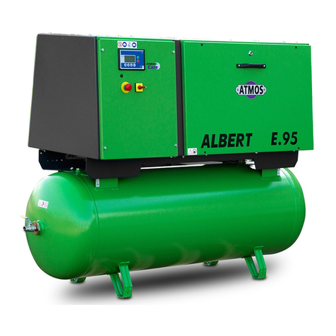
Atmos Albert E95-9-K User manual
Atmos
Atmos Albert E95-10-KR User manual
Atmos
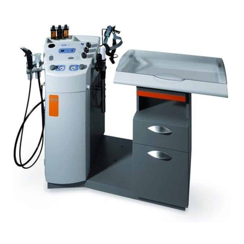
Atmos Albert E95-KR User manual
Atmos
Atmos ATMOS C 21 User manual
Atmos
Atmos Albert E95-9-KRD User manual

Atmos
Atmos PDP 90 Manual
Popular Air Compressor manuals by other brands
Atrium
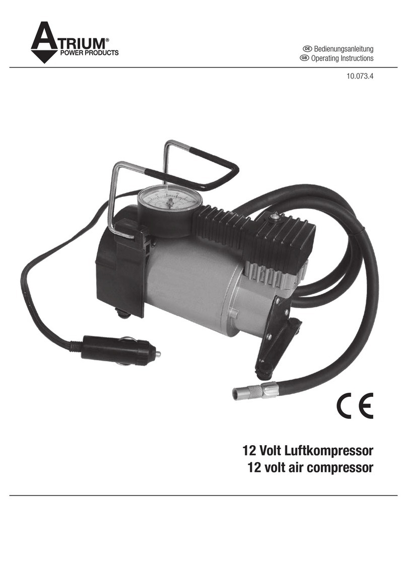
Atrium 12 volt air compressor operating instructions

SALKI
SALKI 83002020 instruction manual
Porter-Cable
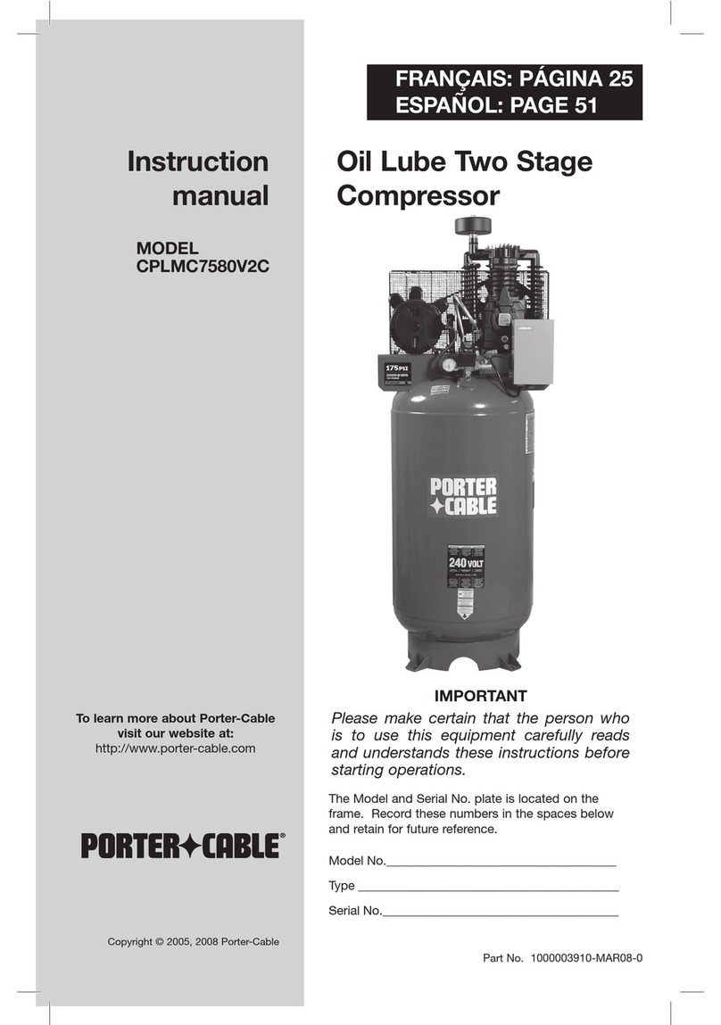
Porter-Cable CPLMC7580V2C instruction manual
Craftsman
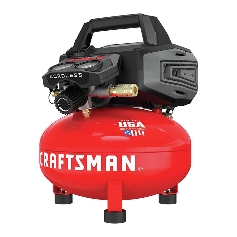
Craftsman CMCC2520 Nstruction manual

EXTOL PREMIUM
EXTOL PREMIUM 8891511 Translation of the original user manual
Truper
Truper COMP-60LB manual
