Southworth PalletPal 360 User manual

Owner’s Manual
PalletPal 360
Level Loader
April 2014
TM
Model # _______________________________
Serial # _______________________________
Placed in Service ________________________
Southworth Products Corp
P.O. Box 1380, Portland, Maine 04104-1380
Phone 800/743-1000 or 207/878-0700 Fax 207/797-4734
www.SouthworthProducts.com

2PALLETPAL 360 OWNER'S MANUAL
Please note: This manual was current at the time of printing. To ob-
tain the latest, most updated version, please contact Southworth’s
Customer Service Department or go to our website: www.South-
worthProducts.com, under the Parts & Service tab you will nd a
complete list of current owner’s manuals to print.
This manual covers all types of PalletPal 360 models including standard
nish steel and special nishes like epoxy or hot dipped galvanized.
The PalletPal 360° was introduced in June 2011, and if your unit
looks like this you have the correct PalletPal 360°owner's manual.
If your unit looks like the picture below you should NOT use this manual. Go
to www.SouthworthProducts.com and download the owner's manual for the
original PalletPal titled 'PalletPal (Spring) Manual'.

PALLETPAL 360 OWNER'S MANUAL 3
Contents
INTRODUCTION ........................................................................................Page 4
RESPONSIBILITY OF OWNERSAND USERS...................................................5
SAFETY .............................................................................................................. 6
Safety Label Compliance.........................................................................7
Installation Notes ................................................................................... 8
Operation Notes – Manual Use ............................................................. 8
Operation Notes – Use with Fork Lift or Stacker.................................... 9
SPECIFICATIONS ............................................................................................. 9
INSTALLATION INSTRUCTIONS .................................................................... 10
Unpacking the Unit .............................................................................. 10
Spring Selection Charts ........................................................................10
Installing the Optional Adjustable Feet ................................................. 11
Installing the Springs ...................................................................... 11-16
OPERATING INSTRUCTIONS ......................................................................... 17
Loading Manually ................................................................................ 17
Removing Loads Manually .................................................................. 17
Operating Safety – Manual use ........................................................... 17
Loading with a Fork Lift ....................................................................... 17
Unloading with a Fork Lift .................................................................... 18
Moving the PalletPal............................................................................. 18
MAINTENANCE ............................................................................................... 18
Routine Periodic Maintenance...............................................................18
TROUBLESHOOTING ......................................................................................19
ORDERING REPLACEMENT PARTS .............................................................. 20
WARRANTY.................................................................................. Back of manual
List of Figures
Fig. 1 Safety Labels.................................................................................... 8
Fig. 2 Pinch Points ..................................................................................... 8
Fig. 3 Orange Spring Installed ................................................................... 8
Fig. 4-17 Step by Step Installation.......................................................... 12 - 16
Fig. 18 Spring Mounting Positions ............................................................. 16
Fig. 19 Loading Manually ........................................................................... 17
Fig. 20 Unloading Manually ....................................................................... 17
Fig. 21 Loading with a Fork Lift .................................................................. 18
Fig. 22 Unloading with a Fork Lift .............................................................. 18
Fig. 23 Moving the PalletPal ...................................................................... 18

4PALLETPAL 360 OWNER'S MANUAL
Introduction
The PalletPalTM Level Loader is a simple device which will automatically maintain a load at the ideal
height for manual loading and unloading. If a palletized load is placed on the unit, the unit gradually
rises as boxes or parts are removed. This automatically maintains the top of the load at the correct
working height.
The unit may also be used in another way. An empty pallet may be placed on the PalletPal. The unit
gradually lowers as boxes or parts are added. Again, this keeps the top of the load at the correct
height. Complete pallets may be loaded or unloaded using a fork lift.
Each PalletPal unit includes a steel or stainless steel scissor lift mechanism and at least one large
compression spring. The springs are chosen to match the weight and height of a fully loaded pallet.
Springs are available for a wide range of weight and height combinations. The PalletPal also includes
a shock absorber (optional on the stainless steel model). This eliminates any tendency for the load
to bounce on the springs.
This manual contains information to help you to learn about the safe and proper installation, use, and
upkeep of your PalletPal unit. Please be sure that this manual is available to anyone who uses or
services the PalletPal unit.
PalletPal units may be used in a wide variety of industrial settings. The instructions in this manual are
not necessarily all-inclusive, as Southworth cannot anticipate all conceivable or unique situations. In
the interest of safety, please read this whole manual carefully. Be familiar with the contents
of this manual before you install or use the PalletPal unit. If you are not sure of the proper
procedure to be followed, please call Southworth Products Corporation for more information.
Southworth’s product warranty is shown on the rear cover of this manual. This instruction manual
is not intended to be or to create any other warranty, express or implied, including any implied
warranty of merchantability or tness for a particular purpose, all of which are hereby expressly
excluded. As set forth more specically in the product warranty, Southworth’s obligation under that
warranty is limited to the repair or replacement of defective components, which shall be the buyer’s
sole remedy,and Southworth shall notbe liable for anyloss, injury,or damage to personsor property,
nor for any direct, indirect, or consequential damage of any kind resulting from the PalletPal unit.

PALLETPAL 360 OWNER'S MANUAL 5
Responsibility of Owners and Users
Inspection and Maintenance
The device shall be inspected and maintained in proper working order in accor-
dance with Southworth’s owner’s manual.
Removal from Service
Any device not in safe operating condition such as, but not limited to, excessive
leakage, missing rollers, pins, or fasteners, any bent or cracked structural mem-
bers, cut or frayed pneumatic lines, damaged or malfunctioning controls or safety
devices, etc. shall be removed from service until it is repaired to the original
manufacturer’s standards.
Deection
It is the responsibility of the user/purchaser to advise the manufacturer where
deection may be critical to the application.
Repairs
All repairs shall be made by qualied personnel in conformance with South-
worth’s instructions.
Operators
Only trained personnel and authorized personnel shall be permitted to operate
the positioner.
Before Operation
Before using the device, the operator shall have:
• Read and/or had explained, and understood, the manufacturer’s operating
instructions and safety rules.
• Inspected the device for proper operation and condition. Any suspect item
shall be carefully examined and a determination made by a qualied per-
son as to whether it constitutes a hazard. All items not in conformance
with Southworth’s specication shall be corrected before further use of the
equipment.
During Operation
The device shall only be used in accordance with this owner’s manual.
• Do not overload.
• Ensure that all safety devices are operational and in place.
Modications or Alterations
Modications or alterations to any Southworth industrial positioning equipment
shall be made only with written permission from Southworth.

6PALLETPAL 360 OWNER'S MANUAL
Safety
The PalletPal unit has been carefully designed to be as safe as possible for operators and service workers. If
you take a few common-sense precautions, you will be able to use the unit safely. However, the PalletPal is a
powerful unit with moving parts, and is capable of causing personal injury if proper precautions are not taken.
Therefore, throughout this manual, Southworth has identied certain hazards which may occur in the use and
servicing of the PalletPal unit, and provided appropriate instructions or precautions which should be taken to
avoid these hazards. In some cases, Southworth has also pointed out the consequences which may occur if
Southworth’s instructions or precautions are not followed. Southworth uses the following system of identifying
the severity of the hazards associated with its products:
DANGER! Immediate hazard which will result in severe personal injury or death.
WARNING! Hazard or unsafe practice which could result in severe personal injury or death.
CAUTION! Hazard or unsafe practice which could result in minor personal injury or property damage.
Please read and follow this instruction manual, including all safety instructions and precautions, carefully
and completely.
Figure 1 shows the safety labels on this unit. Please be sure that all of the labels are in place, and are visible to
the machine operators. Never paint over the labels. If any of the labels are missing, please contact Southworth
for replacements. The safety labels help to protect your workers.
Note: The shock absorber is optional on the stainless model. If the shock absorber is not present,
use a screw driver or a bolt as a maintenance device to hold the lift up. If the shock is with the lift,
use the pivot pin as a device to hold the lift up. See Fig. 8.

PALLETPAL 360 OWNER'S MANUAL 7
SAFETY LABEL COMPLIANCE
To aid in understanding the concept and the importance of the symbol and signal word, the following
has been excerpted from ANSI Z535.4.
4.10 Safety Alert Symbols
A symbol which indicates a potential personal injury hazard. It is composed of an equilateral
triangle surrounding an exclamation mark. The safety alert symbol shall not be used to alert
persons to property-damage-only accidents.
4.1 Signal Words
The meaning of different signal words as dened by ANSI Z535.6 and Z535.4 standards may be
provided in collateral materials. The following artwork may be used for this purpose.
For use with DANGER signal word
(Red Background)
For use with WARNING signal word
(Orange Background)
For use with CAUTION signal word
(Yellow Background)
DANGER indicates a hazardous situation which, if not avoided,
will result in death or serious injury.
WARNING indicates a hazardous situation which, if not avoided,
could result in death or serious injury.
CAUTION, used with the safety alert symbol, indicates a haz-
ardous situation which, if not avoided, could result in minor or
moderate injury.
NOTICE is used to address practices not related to personal
injury.
(Red Background)
(Orange Background)
(Yellow Background)
(Blue Background)

8PALLETPAL 360 OWNER'S MANUAL
WARNING!
After the springs are installed, if the
springs are not seated correctly, or the
twist-lock caps are not tightened, the parts
may pop loose when the unit is used. You
may be hurt, or the load may be damaged.
Operation Notes – Manual Use
WARNING!
Never operate the unit if anyone is sitting
or riding on the rotating ring.
WARNING!
Never operate the unit if the load is off-
center. The load may shift, and you may
be injured. This can also damage the unit.
WARNING!
As the unit moves, keep away from the
“pinch points” where metal parts meet.
See Fig. 2.
WARNING!
Keep the area around the unit clean. Do
not allow any dirt, debris, spilled oil, or
excess grease to collect. These materials
may cause you to slip while the unit is
operating, and you may be injured.
WARNING!
Stay clear of the rotating ring when it is
moving. As the pallet turns, a part of the
load may rotate around and hit you. Never
turn the load when anyone is standing
beside the unit.
Installation Notes
NOTICE
The unit must be installed on a rm, nearly-
level surface. The frame of the unit must
sit rmly on the oor, and the oor must
be level. If the frame is not supported
correctly, stresses may develop in the
frame. The unit may bind or not work
easily. The rotating ring may not rotate
correctly.
Fig. 1.
Safety Labels
A
SOUTHWORTH SMS
3055610 -
-
C
D
B
A
4321
D
C
Portland, Maine 04104-1380
A
B
32DWG NO
DWG. NO.
.5 DATE
1:4 -
5-4-11
60037572
LD LOC DIAG PPAL360
DIMENSIONS ARE IN
PROJECTION 063Z8
CAGE CODE MODEL
SCALE
DATE
WT
REFERENCE
4
REV
32
UNLESS OTHERWISE
C
SIZE SHEET 1 OF 1
SPECIFIED.
SHEET 1 OF 1
60037572
USE OF PROPRIETARY INFORMATION
INCHES
3RD ANGLE
1
DR
LIMITED TO WRITTEN AGREEMENT
CK
TITLE:
FRACTIONS 1/
.XXX .005
.XX .01
ANGLES: Southworth Products Corp.
P.O. Box 1380
- LBS
--05-04-11INITIAL RELEASEA
ECO #REVISED BYDATEDESCRIPTIONREV. REVISIONS
ITEM
NO. QTY. U/M DESCRIPTION PART NO.
3 2 EA SERIAL TAG
2 3 EA BK-LD DCL 1.00X9.00 SOUTHWORTH 5900191
1 2 EA BK-LD DCL 2.00X6.00 CATION, DO NOT LIFT 5900170
2X3 SERIAL TAG CENTERED
ON INNER LEG CROSS TUBE
POCKET EACH SIDE.
APART
CENTERED ON FORK
DECAL 5900170
DECAL 5900191 ON OUTSIDE
OF ANGLE RING EQUALLY
SPACED 120
2X3 SERIAL TAG ON UNDER SIDE OF
STRONGBACK THIS END.
BOM FOR REFERENCE ONLY
THIS DRAWING MUST BE AT REVISION: 'A'
PalletPal 360
PalletPal 360
Fig. 2. Pinch Points

PALLETPAL 360 OWNER'S MANUAL 9
WARNING!
Do not try to use this unit with damaged or
broken pallets. Broken pallets may have
boards or nails which hang down below
the main part of the pallet. As the pallet is
turned, these boards or nails may catch on
the frame of the unit. This can cause the
pallet to stop turning suddenly, causing
the load to shift.
You may be injured, and the unit may be
damaged. The boards or nails on the
bottom of the pallet should not extend
down more than 1/8 inch.
Operation Notes:
Use with Fork Lift or Stacker
You must take some special precautions when using a
fork lift or stacker with the unit:
When loading using a fork lift or stacker –
WARNING!
When adding a load to the unit, lower the
forks completely before removing the
fork lift. The pallet must be completely
supported by the PalletPal. If you do not
do this, the load may be dropped when
Specications
Load capacity.............................400 to 4500 lbs., depending on springs
Load size....................................50" wide x 50" long x 72" high (max.)
Length........................................45 1/4inches
Width (base frame) ....................36 3/4inches
Compressed height....................9 1/2inches
Extended height.........................27 3/4inches
Rotating ring, outside diameter..43 5/8inches
Rotating ring, inside diameter ....40 5/8inches
Adjustment for sloping oors......Can adjust for oor slope up to 1:25
using optional adjustable feet
Net weight..................................380 lbs., with (3) springs installed
you remove the fork lift. The unit or the
load may be damaged, or you may be hurt.
Figure 7 shows the correct way to load
using a fork lift.
When unloading using a fork lift or stacker –
WARNING!
When removing a load from the unit, lift the
load clear of the PalletPal before backing
out the fork lift. If you do not do this, the
top of the unit may jump up when you
remove the fork lift. The unit or the load
may be damaged, or you may be hurt.
Figure 8 shows the correct way to unload
using a fork lift.
When moving the PalletPal -
NOTICE
Do not move the PalletPal while it is loaded.
This will damage the base frame of the
unit. The pockets on the base frame are
designed to support an unloaded PalletPal,
they cannot support any extra weight.

10 PALLETPAL 360 OWNER'S MANUAL
Installation Instructions
Unpacking the PalletPal 360
1. Before you start to install the unit, check for local
codes and ordinances which may apply. It is your
responsibility to obtain any necessary permits.
2. Please read all of these instructions carefully. Be
sure to read and understand all of the warnings.
3. Inspecttheshipping palletcarefullyforany damage
which may have affected the unit. If you see signs of
damage, tell the trucker. Also make a note of this on
the shipping papers which you are asked to sign.
4. Choosethe placewhereyouwant tousetheunit. It
isvery importantthatthePalletPal besetup onasmooth
and at surface. Check the oor surface carefully and
make sure that it is free of all loose debris and dirt.
Usingoptionaladjustablefeet,theunitcancompensate
for a slightly sloping oor (1:25), but the surface must
be smooth and solid.
CAUTION!
The unit must be installed on a smooth at
surface. If the oor is not at, this can create
stresses in the frame of the unit. The unit may
not work properly, or parts of the unit may
wear more quickly than they should. You may
be hurt or the load may be damaged.
Table 1 - Spring selection chart
1 Caution: PalletPal springs are precisely calibrated and will work best within the load weight and height ranges selected. Selection
based on higher or lower than actual weight will result in restricted raising or lowering capability. Should pallet weight or height weight
requirements dramatically change, PalletPal can be adapted in the field at any time by simply changing the spring combination used.
PalletPal 360 Spring Selection Guide
In order to make sure your PalletPal
functions properly you must have the
proper spring configuration. This simple
chart below will allow you to pick the right
spring configuration for your application
based on the weight of your pallet load
and the height of your pallet load.
Weight of Fully Loaded Pallet (lbs.)
0-
400
400-
800
800-
1200
1200-
1600
1600-
2000
2000-
2400
2400-
2800
2800-
3200
3200-
3600
3600-
4000
4000-
4500
58-60” 0011112223 3
56-58” 0011122223 3
54-56” 0011122223 3
52-54” 0111122233 3
50-52” 0111122233 4
48-50” 0111122233 4
46-48” 0111122333 4
44-46” 0111223334 4
42-44” 0112223344 4
40-42” 0112233344 4
38-40” 0112233444 4
36-38” 0112234444 4
34-36” 1122334444 -
32-34” 112334444- -
30-32” 112334444- -
0Range 0 – White Spring (1 Spring)
1Range 1 – Orange Spring (1 Spring)
2Range 2 – Orange and Gray Springs (2 Springs)
3Range 3 – Orange and Purple Springs (2 Springs)
4Range 4 – Orange, Gray, and Purple Springs (3 Springs)
Height of Fully Loaded Pallet
800-743-1000 • SouthworthProducts.com
PalletPal comes complete with rotator ring, fork truck pockets in base
and selected range spring package. Adjustable feet are optional.
1. Fill in the weight of a fully loaded pallet here: ___________
(Do not guess. Get actual weight from prospect or have a pallet weighed)1
2. Fill in the height of a fully loaded pallet here: ___________
(Do not guess. Get actual height from prospect or measure a loaded pallet)1
3. Using the chart below, select the correct PalletPal range: ___________

PALLETPAL 360 OWNER'S MANUAL 11
Fig. 3 Orange Spring Installed
5. Position the PalletPal beside the point where the
unit will be set up.
6. Removethebanding which secures the unit tothe
pallet. Remove all packing material. Shift the unit to
the oor. Support the base as you do this.
7. Check to see that the frame of the unit is sitting
rmly on the oor. Try to move or rock the frame of
the unit. The base frame should be stable, and should
not move. Check to see that the base frame is level.
(If any part of the frame is more than 1/2" out of level in
relation to any other part, you must install the optional
adjustable feet to level the unit. See the instructions
below.)
8. Remove the springs and lay them out on the oor.
9. If you have any questions about the steps in the
installation process, please call Southworth Customer
Service at 1-800-743-1000.
Setting up and Installing the Springs
1. The PalletPal will always have at least one
spring. This spring has an orange mark, and is larger
in diameter than the others. This large orange spring
is always placed in the front of the unit. Figure 3 shows
the position of the rst spring.
The frame of the unit can handle loads of up to 4500
lbs. In order to adapt the unit for different pallet loads,
the springs are changed. The springs are chosen to
match the weight and height of a fully loaded pallet. A
unit may have one to three springs.
Each time the pallet weight or pallet height is changed,
the springs may also need to be changed. Table 1 on
page 10 show how the springs are selected.
Back
(Hinge End) Front
(Roller End)
Optional Adjustable Feet
Adjust each of the feet until the base frame of the PalletPal unit is level. All four of the feet must touch the
oor. Once the settings are correct, tighten the nuts against the mounting frame.

12 PALLETPAL 360 OWNER'S MANUAL
3. The shock absorber is attached to the
top frame of the unit with a pivot pin, and this
is held in place by a linch pin. The pivot pint
is used to hold the table frame in the raised
position. Take a look at the mechanism and
note the positions of the parts. Remove the
linch pin and remove the pivot pin. Lay the
free end of the shock absorber down.
2. The unit is shipped without springs
installed. The installation of the rst spring
(orange) requires two people. Lift off rotating
ring and both yellow bayonets. Set them aside,
they will be installed later.
Fig. 4
Fig. 5
4. With the help of an assis-
tant, lift the top frame until it hits
the upper latch stops.
Fig. 6

PALLETPAL 360 OWNER'S MANUAL 13
Fig. 7
5. While holding both latches up and lift the
top frame pass the latches until it is at its full,
uppermostposition. Have the assistant holdthe
weight and insert the pivot pin in the hole in the
baseframe.See Fig. 8. With the PalletPal in this
full upper most position the orange spring can
be installed.
Fig. 8
6. Insert either
end of the large
orangespring into
the lower pocket.
Be sure the bot-
tom spring coil
is positioned out-
sidethealignment
tab as shown.
Fig. 9
Alignment Tab

14 PALLETPAL 360 OWNER'S MANUAL
7. Grasp the spring by the second or
thirdcoildown from the top (do NOTgrasp
the top coil or rung) and push the spring
downandundertheedgeofthetopframe.
Fig. 10
8. While pushing down to
compress spring push it forward
into the pocket up under the top
frame. It will "snap" into position
when completely in the pocket.
Fig. 11
Fig. 12 Fig. 13
CORRECT
Fully inserted into pocket
INCORRECT
Spring NOT fully inserted into pocket

PALLETPAL 360 OWNER'S MANUAL 15
Fig. 14
9. Remove the shock absorber pivot pin. Push down on top frame until
latches engage. (Both latches will drop into place).
10. Reinstall the shock absorber pivot pin and linch pin.
Fig. 15

16 PALLETPAL 360 OWNER'S MANUAL
Fig. 16 Fig. 17
11. Install additional springs as needed
through the bayonet openings. Reinsert the
yellowbayonets and twisttolockthem in place.
12. Reinstall the rotator ring.
Before using the unit, do a safety check. Be sure that each of the spring bayonet
caps is in place and rotated to their locked position. Check the top and bottom of
each spring to be sure it is seated correctly. Check the linch pin at the top of the
shock absorber. These checks are very important.
The PalletPal 360 is now ready for use!
13. Figure 4 shows the position of additional springs if needed. Double-check to be sure you have the correct
springs. Refer to Table 1 on page 10 and see that you have the correct springs for your application.
Fig. 18
Spring Mounting Positions
Orange
spring
Range #1
Rear
Front
Orange
spring
Grey
spring Purple
spring
Range #2
Rear
Front
Orange
spring
Range #3
Rear
Front
Purple
spring
Orange
and Grey
springs
Range #4
Rear
Front
Front= roller end of legs
Rear= hinge end of legs
PALLETPAL 360 OWNER'S MANUAL 17
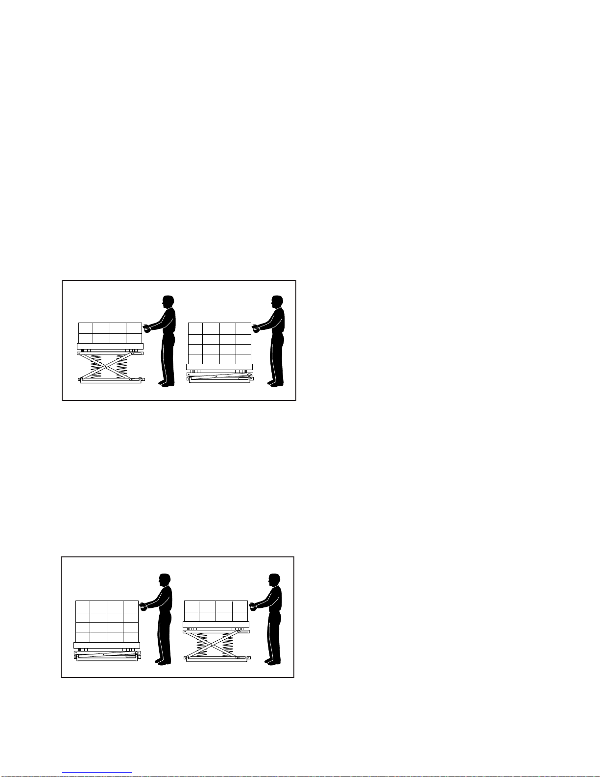
Operating Instructions
Loading Manually
Addboxesor parts until the pallet isfull. Loadthe pallet
in layers. Use the rotating ring to position the pallet to
eliminate walking around. The unit will gradually lower
the pallet until it reaches the bottom. See Fig. 19.
Removing Loads Manually
Removeboxesorpartsuntil the pallet is empty. Unload
the pallet in layers. Use the rotating ring to position the
pallet to eliminate walking around. The unit will gradu-
ally raise the pallet. See Fig. 20.
Operating Safety - Manual Use
1. Do not use this unit with a load greater than the
rated load. This includes the weight of the payload and
the weight of the pallet. Table 1 on page 10 shows how
to be sure you have the correct spring combination for
your application.
2. Never push the load off of the side of the unit. If
you do this, the frame of the unit may jump upward.
3. Never use the unit when anyone is sitting or riding
on the rotating ring.
4. Do not try to use this unit with damaged or broken
pallets. Broken pallets may have boards or nails which
hang down below the main part of the pallet. As the
pallet is turned, these boards or nails may catch on the
frame. The pallet may stop turning suddenly and this
can cause the load to shift. You may be injured and
the unit may be damaged. If the boards or nails on the
bottom of the pallet extend down more than 1/8inch,
they will interfere with the turning action.
5. Stay clear of the rotating ring when it is moving.
As the pallet turns, a part of the load may rotate around
and hit you.
6. Keep the area around the unit clean. Do not allow
any dirt, debris, spilled oil, or excess grease to collect.
These materials may cause you to slip while the unit is
operating and you may be injured.
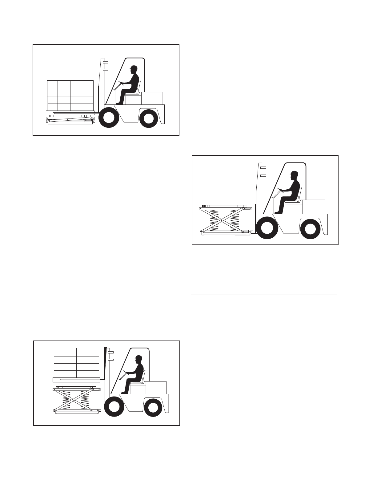
Loading with a Fork Lift
1. Place the load on the lift, then lower the fork lift.
Before removing the load, be sure the unit is carrying
the weight, not the fork lift. See Fig. 21.
• Lower the load until the springs on the PalletPal
are fully compressed.
• Be sure the forks on the lift are clear of the inside
of the pallet.
WARNING!
If you skip these steps, the load may drop
suddenly when you remove the fork lift.
You may be hurt or the unit or load may
be damaged.
WARNING!
Never drop the load on the rotating ring. If
you do this while the rotating ring is mov-
ing, the load may shift. You may be injured
or the unit may be damaged. If you drop
the load while the rotating ring is stopped,
the unit may be damaged.
Fig. 19
Loading Manually
Fig. 20
Unloading Manually
CAUTION!
Rotate the pallet load. Never place
your hands on the rotator ring. You
may be hurt.
18 PALLETPAL 360 OWNER'S MANUAL
Fig. 22
Unloading with a Fork Lift
Fig. 21
Loading with a Fork Lift
Fig. 23
Moving the Pallet Pal
2. Be sure the load is centered on the unit.
WARNING!
If the load is off-center, it may shift when
the rotating ring is turned. You may be hurt
or the unit or load may be damaged.
Unloading with a Fork Lift
1. Inserttheforks fully into the pallet, and lift thepallet
straight up and clear of the top of the unit. See Fig. 22.
• Raise the pallet until the springs on the PalletPal
are fully extended.
• Be sure the pallet clears the top of the rotating
ring before you move the fork lift.
WARNING!
If you skip these steps, the unit may jump
up suddenly when you remove the pallet.
You may be hurt or the unit or load may
be damaged.
Moving the Pallet Pal
NOTICE
Do not move the Pallet Pal while it is load-
ed. This will damage the base frame of the
unit. The pockets on the base frame are
designed to support an unloaded PalletPal,
but cannot support any extra weight.
1. Remove any load from the top of the Pallet Pal.
2. Insert the forks into the pockets in the base frame.
See Fig. 23.
Maintenance
Routine Periodic Maintenance
Every 90 days -
• Check for loose hardware and signs of excessive
wear. On the models where the shock absorber
is used, check for signs of leakage.
• Check to be sure that the unit is placed on a rm
level surface. If the optional feet are installed, be
sure that all four feet are touching the oor and
are locked in position.

PALLETPAL 360 OWNER'S MANUAL 19
Troubleshooting
Troubleshooting Check List
Problem Possible Cause Check This
The unit lowers too easily (too
early). The spring combination may be too
weak for the load. Check the spring ratings.
See Table 1 on page 10.
The unit does not lower
enough (too late). The spring combination may be too
strong for the load. Check the spring ratings.
See Table 1 on page 10.
The top of the unit rotates
away from you. The frame of the unit may not be level. Move the unit to a level sur-
face or install the optional
adjusting feet.
The top of the unit bounces. The shock absorber may be damaged. Check for leaks or dents.
Replace if damaged.
Excessive “rumble” when the
ring rotates Wear or lack of lubrication to bearings
under rotating ring. Remove turntable, lubricate
or replace bearings.
Wear or metal aking from un-
derside of rotating ring. Normal condition caused by work-hard-
ening of metal. No repair necessary. This
will stop once the rotator ring
wears in.

20 PALLETPAL 360 OWNER'S MANUAL
Ordering Replacement Parts
Southworth has carefully chosen the components in your unit to be the best available for the purpose.
Replacement parts should be identical to the original equipment. Southworth will not be responsible
for equipment failures resulting from the use of incorrect replacement parts or from unauthorized
modications to the unit.
Southworth can supply all replacement parts for your PalletPal. With your order, please include the
model number and the serial number of the unit. You can nd these numbers on the name plate. This
plate is located within the scissors mechanism.
To order replacement parts, please call the Parts Department at (207) 878-0700 or (800) 743-1000.
Parts are shipped subject to the following terms:
• FOB factory
• Returns only with the approval of our Parts Department.
• Payment net 30 days (except parts covered by warranty).
• Freight collect (except parts covered by warranty).
Parts replaced under warranty are on a “charge-credit” basis. We will invoice you when we ship the
replacement part, then credit you when you return the worn or damaged part, and we verify that it is
covered by our warranty. Labor is not covered under our warranty for Parts orders.
Parts Department
Southworth Products Corp.
P.O. Box 1380
Portland, Maine, 04104-1380
Telephone: (800)743-1000 or (207)878-0700
FAX: (207)797-4734
Other manuals for PalletPal 360
2
Table of contents
Popular Valve Positioner manuals by other brands

Samson
Samson 3730-4 Configuration manual

halstrup-walcher
halstrup-walcher PS 3 EIP Series instruction manual

Festo
Festo CMSX C-U-F1 Series Translation of the original instructions

Aventics
Aventics R434001244 Service information

Burkert
Burkert 8692 Supplement to operating instructions

Pepperl+Fuchs
Pepperl+Fuchs Profinet PCV50-F200-B17-V1D manual


