Econ 3300 Series User manual
Installation and Operating manual
Econ®Series 3300 Smart Valve Positioner www.eriks.com www.eriks.com
1
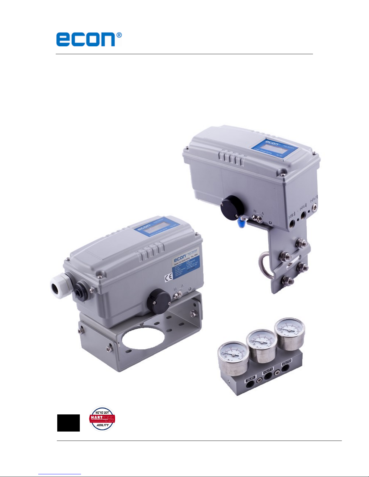
Econ®Series 3300
Smart Valve Positioner
Version 2

Installation and Operating manual
Econ®Series 3300 Smart Valve Positioner www.eriks.com www.eriks.com
2
1INTRODUCTION ............................................................................................................................. 4
1.1 GENERAL INFORMATION FOR THE USERS ...................................................................................... 4
1.2 MANUFACTURER WARRANTY ....................................................................................................... 4
2PRODUCT DESCRIPTION ............................................................................................................. 5
2.1 GENERAL.................................................................................................................................... 5
2.2 MAIN FEATURES AND FUNCTIONS................................................................................................. 5
2.3 LABEL DESCRIPTION ................................................................................................................... 5
2.4 PRODUCT NUMBER ..................................................................................................................... 6
2.5 PRODUCT SPECIFICATION ............................................................................................................ 7
2.6 PARTS AND ASSEMBLY ................................................................................................................. 8
2.7 PRODUCT DIMENSION ................................................................................................................. 9
3INSTALLATION ............................................................................................................................. 10
3.1 SAFETY ....................................................................................................................................10
3.2 FIGURE 3301/3302 INSTALLATION ............................................................................................. 10
3.2.1 Installation Steps ............................................................................................................. 10
3.3 FIGURE 3301 DIRECT-MOUNTING INSTALLATION .........................................................................13
3.3.1 Installation Steps ............................................................................................................. 13
3.4 FIGURE 3303/3304 INSTALLATION ............................................................................................. 14
3.4.1 Bracket information .........................................................................................................14
4CONNECTIONS ............................................................................................................................ 15
4.1 SAFETY ....................................................................................................................................15
4.2 SUPPLY PRESSURE CONDITION .................................................................................................15
4.3 PIPING CONDITION ....................................................................................................................15
4.4 CONNECTION –ACTUATOR ........................................................................................................16
4.4.1 Single acting actuator –Figure 3301 & 3303 .................................................................. 16
4.4.2 Double acting actuator –Figure 3302 & 3304................................................................. 16
4.5 CONNECTION –POWER.............................................................................................................16
4.5.1 Safety .............................................................................................................................. 16
4.5.2 Terminal Overview ...........................................................................................................17
4.5.3 Ground.............................................................................................................................17
5ADJUSTMENTS ............................................................................................................................ 18
5.1 AUTO/MANUAL SWITCH (A/M SWITCH).......................................................................................18
5.2 VARIABLE ORIFICE ADJUSTMENT................................................................................................18
5.3 OPTION PCB ADJUSTMENT .......................................................................................................19

Installation and Operating manual
Econ®Series 3300 Smart Valve Positioner www.eriks.com www.eriks.com
3
6OPERATION ..................................................................................................................................20
6.1 SAFETY ....................................................................................................................................20
6.2 BUTTON DESCRIPTION .............................................................................................................. 20
6.3 RUN MODE (RUN) ....................................................................................................................20
6.3.1 Auto Calibration (AUTO CAL) .........................................................................................21
6.3.2 Manual Mode (MANUAL) ................................................................................................22
6.3.3 Parameter Mode (PARAM)..............................................................................................22
6.3.4 Hand Calibration Mode (HAND CAL) .............................................................................. 24
6.3.5 Valve Mode (VALVE) .......................................................................................................27
6.3.6 View Mode (VIEW) ..........................................................................................................31
7ERROR AND WARNING CODE ................................................................................................... 32
7.1 ERROR CODE............................................................................................................................32
7.2 WARNING CODE ........................................................................................................................ 33
8SOFTWARE MAP ...............................................................................................................34
9CE DECLARATION OF CONFORMITY........................................................................................ 35
10 MANUFACTURER CONTACT DETAILS: .................................................................................36

Installation and Operating manual
Econ®Series 3300 Smart Valve Positioner www.eriks.com www.eriks.com
4
1 Introduction
1.1 General Information for the users
Thank you for purchasing the Econ®series 3300 Smart Valve Positioner. Each product has
been fully inspected after its production to offer you the highest quality and reliable
performance. Please read the product manual carefully prior to installing and commission the
product.
For safety, it is important to follow the instructions in the manual. Econosto will not be
held responsible for any damages caused by user’s negligence.
The manual should be provided to the end-user.
Any modifications or repairs to the product may only be performed if expressed in this
manual.
The manual can be altered or revised without any prior notice. Any changes in
product’s specification, design, and/or any components may not be printed immediately
but until the following revision of the manual.
The manual should not be duplicated or reproduced for any purpose without prior
approval.
1.2 Manufacturer Warranty
For the safety, it is important to follow the instructions in the manual. Manufacturer will
not be responsible for any damages caused by user’s negligence.
Manufacturer will not be responsible for any damages or accidents as a result of any
alteration or modification of the product and its parts. If any alteration or modifications
are necessary, please contact Econosto directly.
Manufacturer warrants the product from the date of original purchase of the product for
one (1) year, except as otherwise stated.
Manufacturer warranty will not cover products that have been subjected to abuse,
accidents, alterations, modifications, tampering, negligence, misuse, faulty installation,
lack of reasonable care, repair or service in any way that is not contemplated in the
documentation for the product, or if the model or serial number has been altered,
tampered with, defaced or removed; damages that occurs in shipment, due to act of
God, failure due to power surge, or cosmetic damage. Improper or incorrectly
performed maintenance will void this limited warranty.
Installation and Operating manual
Econ®Series 3300 Smart Valve Positioner www.eriks.com www.eriks.com
5
2 Product Description
2.1 General
Econ®series 3300 Smart Valve Positioner accurately controls valve stroke in response to an
input signal of 4-20mA from a process controller. An built-in micro-processor optimizes the
positioner’s performance and provides unique functions such as Auto-Calibration, PID
Controlled , Alarms, and HART®Protocol Communications.
2.2 Main Features and Functions
LCD display enables users to monitor the positioner status.
Positioner operates normally during sudden changes in supply pressure and / or high
vibration environment.
Low air consumption level and low voltage use (8.5 V) yield to lower plant operating
costs. The series 3300 is compatible with most of controllers.
Variable orifices can be used to minimize the hunting occurrence and optimize operating
conditions.
Valve system feedback is greatly improved by the accuracy and fast response of the
series 3300.
Different valve characteristics can be adjusted –Linear, Quick Open, Equal Percentage,
and Custom which user can make 16 points characterizations.
Tight Shut –Close and Shut - Open can be set.
PID parameters can be adjusted in the field without any additional communicator.
A/M switch can be used to direct supply air to the actuator or to manually operate the
positioner or valve.
Split range 4-12mA or 12-20mA can be set.
Operating temperature is -30 ~ 85’C.
Manual Operation allows the user to operate the valve manually.
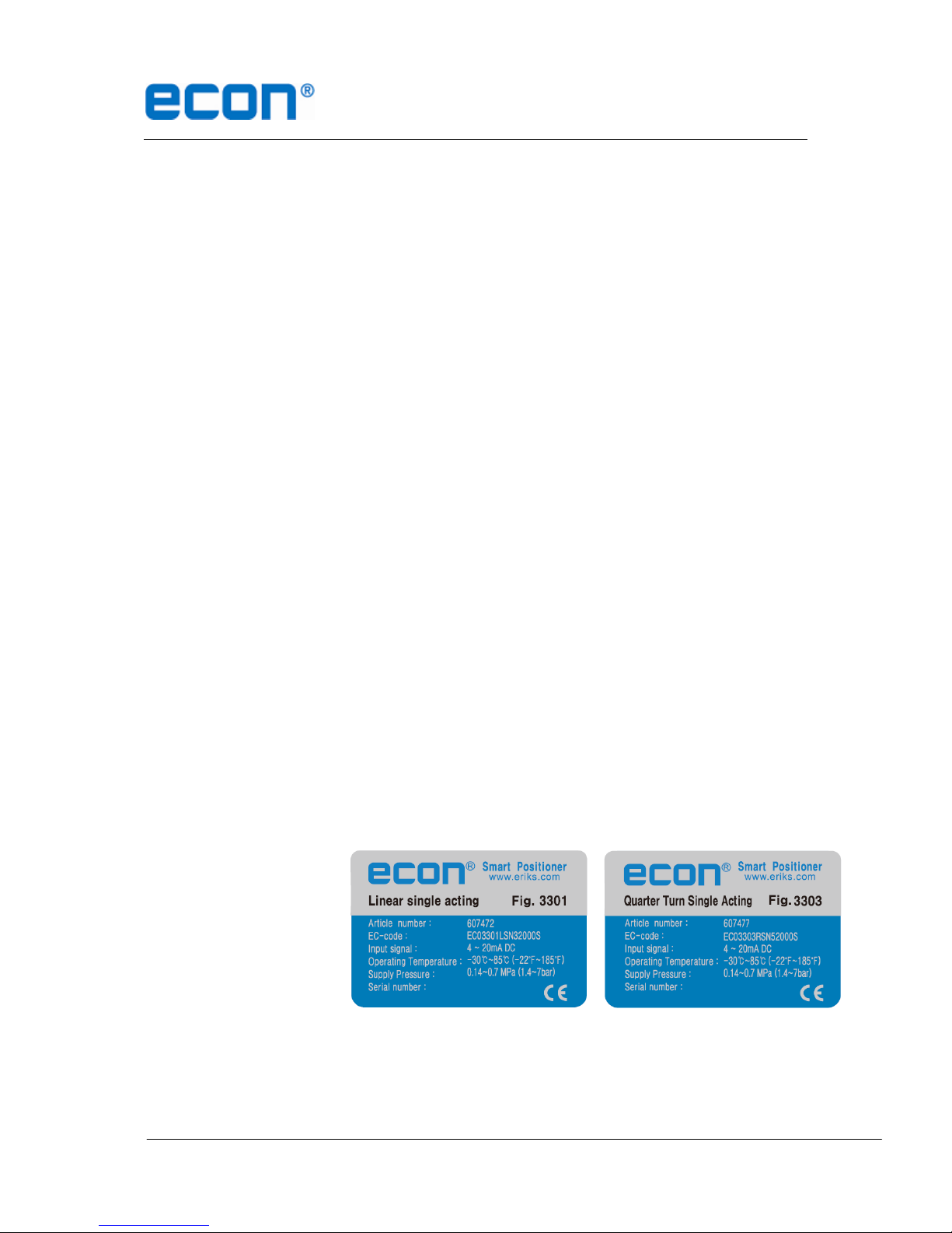
2.3 Label Description
Series 3300 Body Label
A. Article number: Indicates the short item ordering code.
B. EC-code: Indicates the Econosto item number.
C. Input Signal: Indicates input signal range.
D. Operating Temp.: Indicates the allowable operating temperature.
E. Supply Pressure: Indicates the supply pressure range.

Installation and Operating manual
Econ®Series 3300 Smart Valve Positioner www.eriks.com www.eriks.com
6
2.4 Product Number
** Figure 3301 can be used for direct-mounting application.
Installation and Operating manual
Econ®Series 3300 Smart Valve Positioner www.eriks.com www.eriks.com
7
2.5 Product Specification
Figure
3301
3302
3303
3304
Motion type
Linear
Rotary
Acting Type
Single
Double
Single
Double
Input Signal
4~20mA DC
Min. Current Signal
3.2mA(Standard), 3.8mA(HART®Included)
Supply Pressure
0.14~0.7 MPa (1.4~7 bar)
Stroke
10~150 mm
0~90°
Impedance
Max.450Ω @ 20mA DC
Air Connection
1/4” NPT
Gauge Connection
1/8” NPT
Conduit Entry
½” NPT with gland for 8 mm cable
Protection Grade
IP66
Explosion Proof
Non-Explosion Proof
Ambient Temp.
Operating Temp. :-30~85℃
Linearity
±0.5% F.S.
Hysteresis
0.5% F.S.
Sensitivity
±0.2% F.S
Repeatability
±0.3% F.S
Flow Capacity
70 LPM (Sup.=0.14 MPa)
Air Consumption
Below 2 LPM (sup = 0.14 MPa), Below 3 LPM (sup = 0.7MPa)
Output Characteristic
Linear, Quick Open, EQ%, User Set (16 point)
Vibration
No Resonance up to 100Hz @ 6G
Humidity
5-95% RH @ 40℃
Communication
HART®Communication
Feedback Signal
4~20mA (DC 10~30V)
Material
Aluminum Die-casting
Weight
2.0kg
Painting
Epoxy Powder Coating
Tested under ambient temperature of 20’C, absolute pressure of 760mmHg, and humidity of 65%.
Installation and Operating manual
Econ®Series 3300 Smart Valve Positioner www.eriks.com www.eriks.com
8
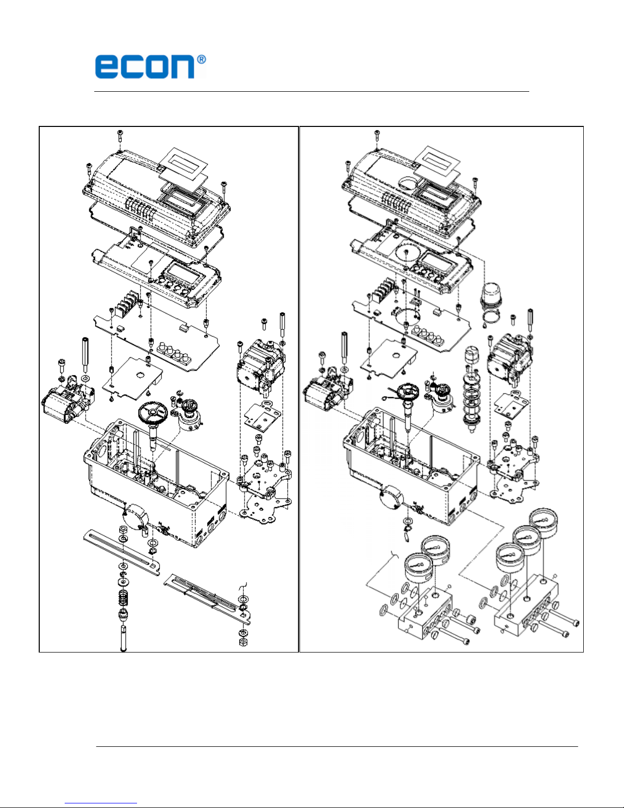
2.6 Parts and Assembly
Figure 3301/3302 exploded view Figure 3303/3304 exploded view
Installation and Operating manual
Econ®Series 3300 Smart Valve Positioner www.eriks.com www.eriks.com
9
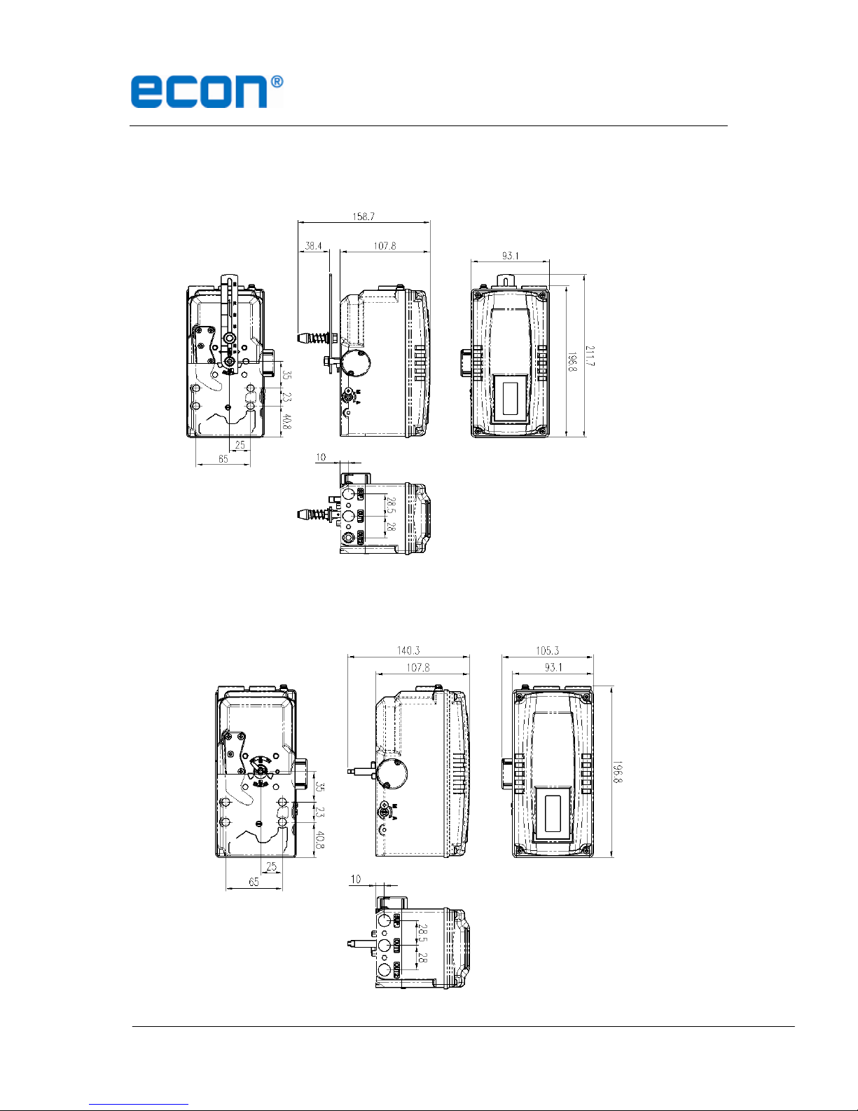
2.7 Product Dimension
Figure 3301/3302
Figure 3303/3304

Installation and Operating manual
Econ®Series 3300 Smart Valve Positioner www.eriks.com www.eriks.com
10
3 Installation
3.1 Safety
When installing a positioner, please ensure to read and follow safety instructions.
Any input or supply pressures to valve, actuator, and / or to other related devices must
be turned off.
Use bypass valve or other supportive equipment to avoid entire system “shut down”.
Ensure there is no remaining pressure in the actuator.
3.2 Figure 3301/3302 Installation
Figure 3301/3302 should be installed on linear motion valves such as globe or gate type
which uses spring return type diaphragm or piston actuators. The following components are
supplied in the linear positioner kit:
Positioner unit
Feedback lever and lever spring
Bar slide assembly
Standard linear bracket
2 pcs x U-bolt M8
2 pcs x M8 hexagonal headed bolts
4 pcs x M8 spring washer
6 pcs x M8 plate washer
4 pcs x M8 nuts
½” NPT gland for 6-8 mm cable diameter
(air connections and air hose to be supplied by customer)
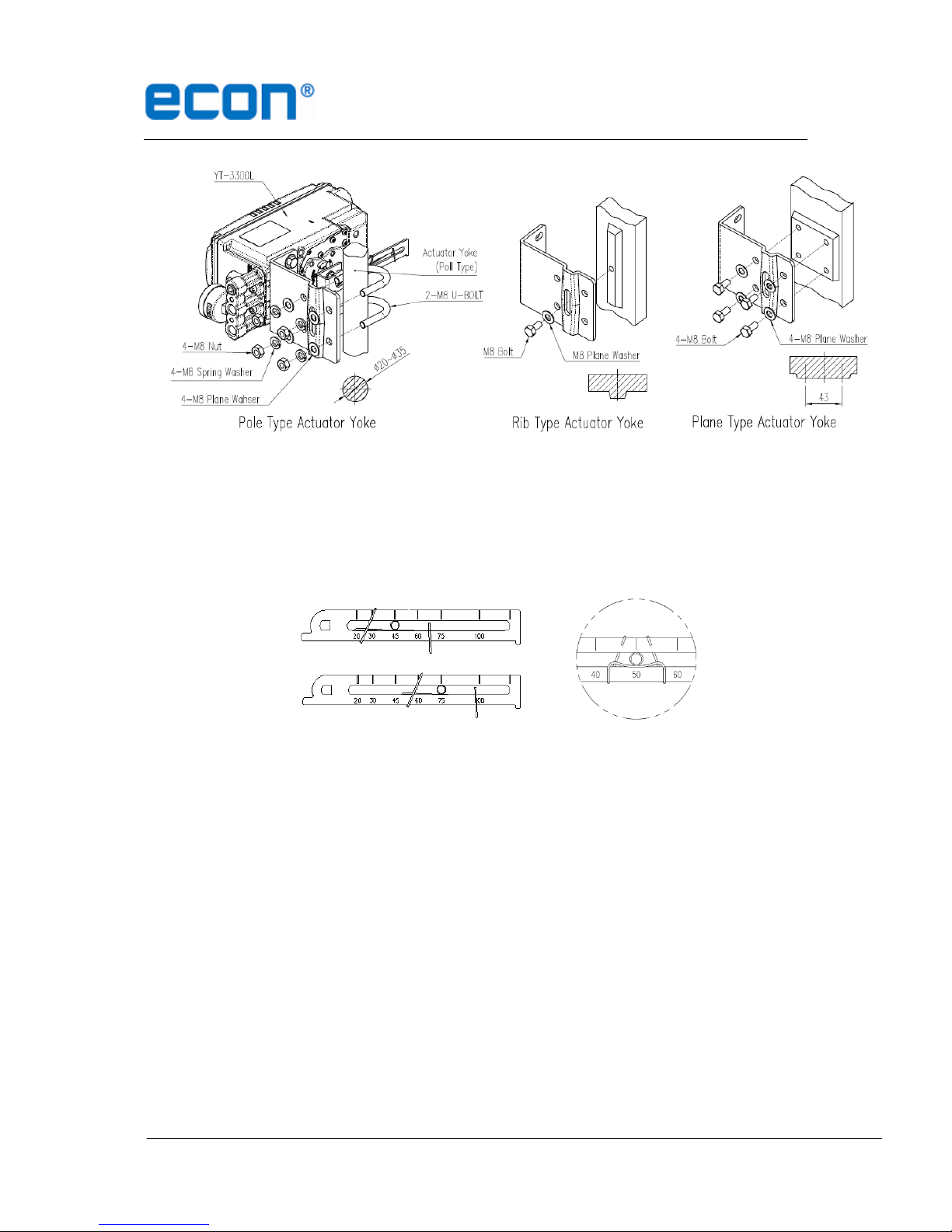
3.2.1 Installation Steps
1. A correct bracket must be used in order to mount the positioner on the actuator yoke.
Please consider following important points when a custom bracket is being designed.
Positioner’s feedback lever must be parallel to the ground at 50% of the valve stroke.
2. Feedback lever connection with the coupling of the actuator should be installed in such a
way that the valve stroke length coincides with the corresponding figure in “mm”marked
on the feedback lever. Improper setting may cause poor linearity and may create
unnecessary hunting during operation.
Assemble the positioner with the bracket supplied by fastening the bolts. Please refer
to the back of the positioner for size of the bolts. The standard bolt size is M8.
Installation and Operating manual
Econ®Series 3300 Smart Valve Positioner www.eriks.com www.eriks.com
11
Figure 3301/3302
3. Check the valve stroke. The stroke marks are indicated on the feedback lever of the
positioner. Position the connection pin at the number on the feedback lever which
corresponds to the desired valve stroke. To adjust, move the bracket, the connection
pin or both.
Correct way of Pin Insertion
4. Attach the bar slide assembly with the supplied mounting bolts onto the actuator coupling.
5. Mount the positioner with the bracket and the U-bolts onto the actuator yoke –DO NOT
TIGHTEN POSITIONER COMPLETELY.
6. Connect supply pressure to the actuator temporarily. Supply enough supply pressure to
the actuator in order to position the actuator clamp at 50% of the total valve stroke.
7. Insert the connection pin of the feedback lever in to the bar slide assembly. The pin
should be inserted when the actuator clamp is at 50% of the total valve stroke.

Installation and Operating manual
Econ®Series 3300 Smart Valve Positioner www.eriks.com www.eriks.com
12
Correct way to connect feedback lever, connection pin, and lever spring
8. Check if feedback lever is parallel to the ground at 50% of the valve stroke. If it is not
parallel, adjust the bracket or feedback link bar to make parallel. Improper installation
may cause poor linearity and may create unnecessary hunting during the operation.
9. After installing the positioner, operate the valve from 0% to 100% stroke by using direct
air to the actuator (manual position). On both 0% and 100%, the feedback lever should
not touch the lever stopper, which is located on the back of the positioner. If the
feedback lever touches the stopper, the positioner should be installed further away from
the yoke.
Feedback lever should not touch lever stopper 0% ~ 100% valve stroke.
10. After the installation, tighten all of the bolts on the bracket, the feedback lever, and the
connection pin.
Installation and Operating manual
Econ®Series 3300 Smart Valve Positioner www.eriks.com www.eriks.com
13
3.3 Figure 3301 Direct-Mounting Installation
Figure 3301 can be installed on direct-mounting / tube-less type actuator.
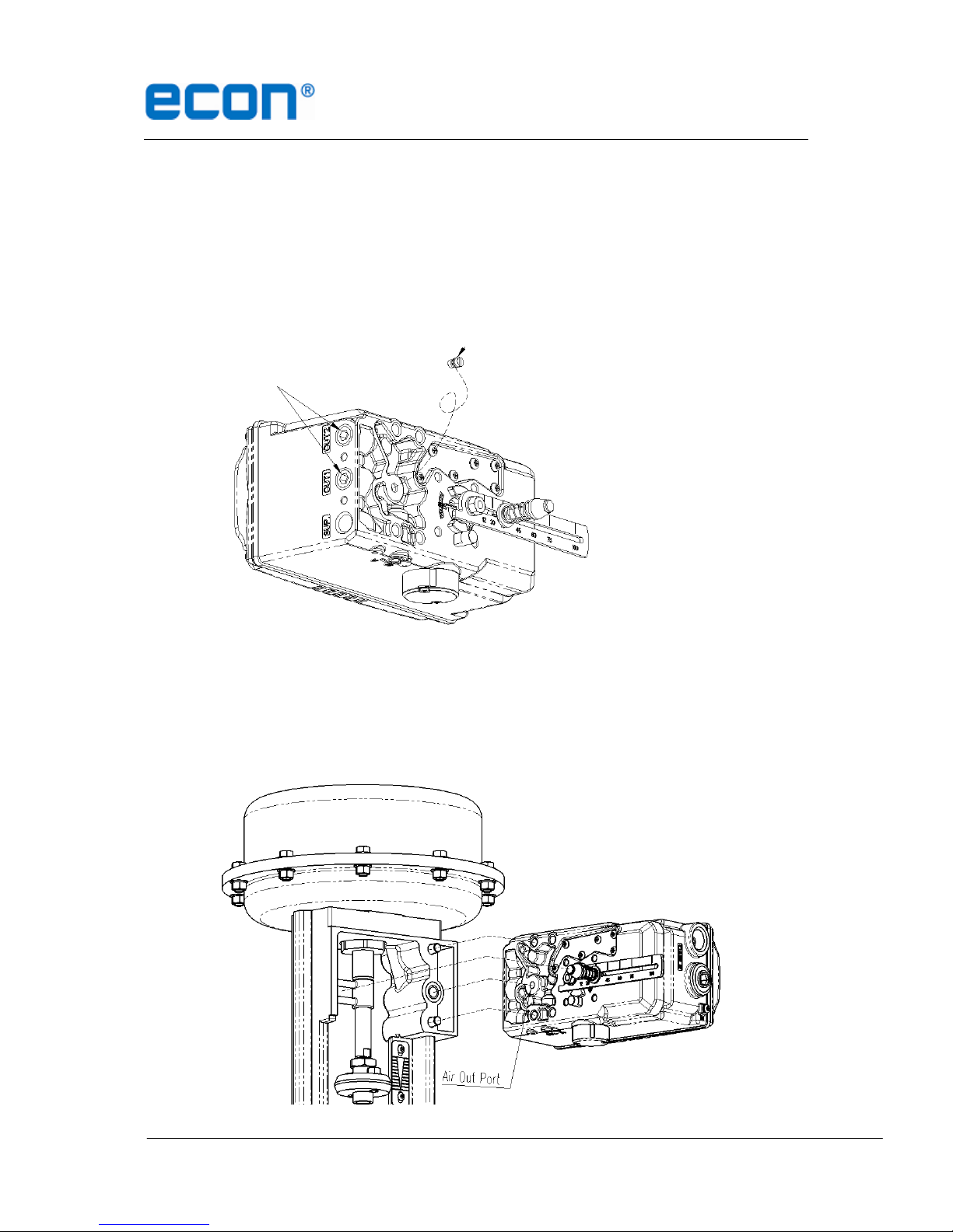
3.3.1 Installation Steps
1. Please remove the plug which blocks OUT port on the back of the figure 3301 unit. OUT
ports on the side of the positioner should be blocked by plugs.
2. Mount figure 3301 onto actuator’s yoke by using 2 bolts. As you mount the positioner,
please be careful not to lose O-rings from the air channel. Please ensure that the lever
adapter connection has been properly installed onto actuator’s stem before tightly
fastened.
Remove
Block

Installation and Operating manual
Econ®Series 3300 Smart Valve Positioner www.eriks.com www.eriks.com
14
3.4 Figure 3303/3304 Installation
Figure 3303/3304 should be installed on rotary motion valve such as ball or butterfly type
which uses rack and pinion, scotch yoke or other type of actuators which stem rotates 90
degrees. The following components are supplied in the quarter turn positioner kit:
Positioner unit
Standard rotary bracket
8 pcs x M6 hexagonal headed bolts
4 pcs x M6 spring washer
½” NPT gland for 6-8 mm cable diameter
(Mounting bolts and washers to actuator, air connections and air hose to be supplied by
customer)
3.4.1 Bracket information
The bracket supplied standard with figure 3303/3304 is made out of two components. The
bracket is designed to fit onto the actuator with 20 mm stem height (H). If actuator
stem height (H) is 30 mm or 50 mm, the bracket must be adjusted. Please refer to
below table how to adjust the bracket.

Installation and Operating manual
Econ®Series 3300 Smart Valve Positioner www.eriks.com www.eriks.com
15
Actuator stem
Height (H)
Markings of bolt holes
A-L & A-R
B-L & B-R
20 mm
H : 20
H : 20, 30
30 mm
H : 30
H : 20, 30
50 mm
H : 50
H : 50
Using hexagonal bolts and washer, fasten figure 3303/3304 with the supplied bracket. Do
not tighten bolts completely before correct mounting of figure 3303/3304 has been confirmed.
Insert figure 3303/3304 main shaft into actuator’s stem, and place the bracket align to the
actuator’s bolt holes. After the alignment, please fasten all of the bolts.
4 Connections
4.1 Safety
Supply pressure should be clean and dry air –avoiding moisture, oil or dust.
It is always recommended to use an air filter regulator.
The operation of this positioner has only been tested with clean air. For gases
other than clean air please contact Econosto for suitability.
4.2 Supply Pressure Condition
Dry air with at least 10℃lower than ambient temperature.
Avoid dusty air. Positioner’s inner filter can only filter 5 micron or larger.
Avoid oil.
Comply with ISO 8573-1, Class 2 (solid particle size and density and oil content).
Supply pressure range is 0.14~0.7 MPa (1.4~7 bar)
Set air filter regulator’s pressure level 10% higher than actuator’s spring range pressure.
4.3 Piping Condition
Ensure inside of pipe is clean of obstructions.
Do not use pipeline that is squeezed or shows any type of damages.
Pipeline should have more than 6mm of inner diameter (10mm outer diameter) to
maintain flow rate.
The length of pipeline system should not be extremely long. Longer pipeline system
may affect flow rate due to the friction inside of the pipeline.

Installation and Operating manual
Econ®Series 3300 Smart Valve Positioner www.eriks.com www.eriks.com
16
4.4 Connection –Actuator
4.4.1 Single acting actuator –Figure 3301 & 3303
Singe acting type positioner is set to use OUT1 port. OUT1 port should be connected with
the supply pressure port of the actuator when using single acting type of spring return
actuator.
Single acting linear (left) and rotary (right) type actuator
4.4.2 Double acting actuator –Figure 3302 & 3304
Double acting type positioner is set to use OUT1 and OUT2 port. As input signal increases,
the supply pressure will be supplied through OUT1 port.
Double acting linear (left) and rotary (right) type actuator
4.5 Connection –Power
4.5.1 Safety
Conduit entry connection tap is 1/2” NPT with a conduit for 8 mm cable.
Before connecting terminal, ensure that the power is off completely. Do not open the
cover when the power is still alive.
Please use insulated electrical connection ring-type lug to protect against vibration or
any other external impact.
Positioner with PTM options must be supplied 10~28V DC separately. It should not
exceed 30V DC.

Installation and Operating manual
Econ®Series 3300 Smart Valve Positioner www.eriks.com www.eriks.com
17
Positioner should be grounded.
Please use twisted cable with conductor section min. 1.25mm2and suitable for 600V
(complying to the conductor table of NEC Article 310.) The outer diameter of the cable
should be between 6.35 ~ 8 mm. Use shield wire to protect against electro-magnetic
field and noise.
Please do not install the cable near high noise equipments, such as an high-capacity
transformer or motor.
4.5.2 Terminal
Overview
Positioner Terminal
IN +: Input Signal (+)
IN -: Input Signal (-)
FG: Ground
OUT+: Feedback Signal (+) (if mounted)
OUT-: Feedback Signal (-) (if mounted)
4.5.3 Ground
1. Ground connection must be done before operating the positioner.
2. Open terminal cover and locate ground terminal plate on the right hand bottom side of
the terminal plate. The outer cable entry is located at outside of the terminal. Please
make sure that the resistance is less than 100 Ohm.
3. When using external ground, use (+) screw driver to unscrew the ground bolts. Insert
outside ground bolts and spring washer into ring type terminal of the ground cables and
tighten them with bolts.
4. When using internal ground, use 3mm wrench to loosen locking bolts of the terminal box
cover.
Installation and Operating manual
Econ®Series 3300 Smart Valve Positioner www.eriks.com www.eriks.com
18
5 Adjustments
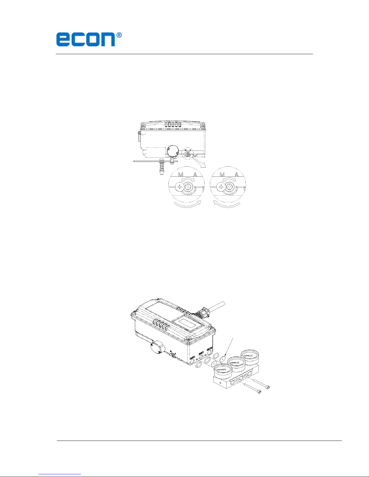
5.1 Auto/Manual Switch (A/M Switch)
Auto/Manual Switch allows the positioner to be functioned as by-pass. If switch is set as
Auto, the positioner will operate per input signal. If switch is set as Manual, the positioner
will send supply pressure directly to the actuator.
5.2 Variable Orifice Adjustment
Extremely small size of the actuator can cause hunting of the positioner. To adjust flow rate
to the actuator, variable orifice can be inserted. The size of orifice is Ø 1 mm. Please note
that these orifices can only be used in conjunction with a gauge block. The orifices are
supplied standard with the optional gauge block.
Installation and Operating manual
Econ®Series 3300 Smart Valve Positioner www.eriks.com www.eriks.com
19
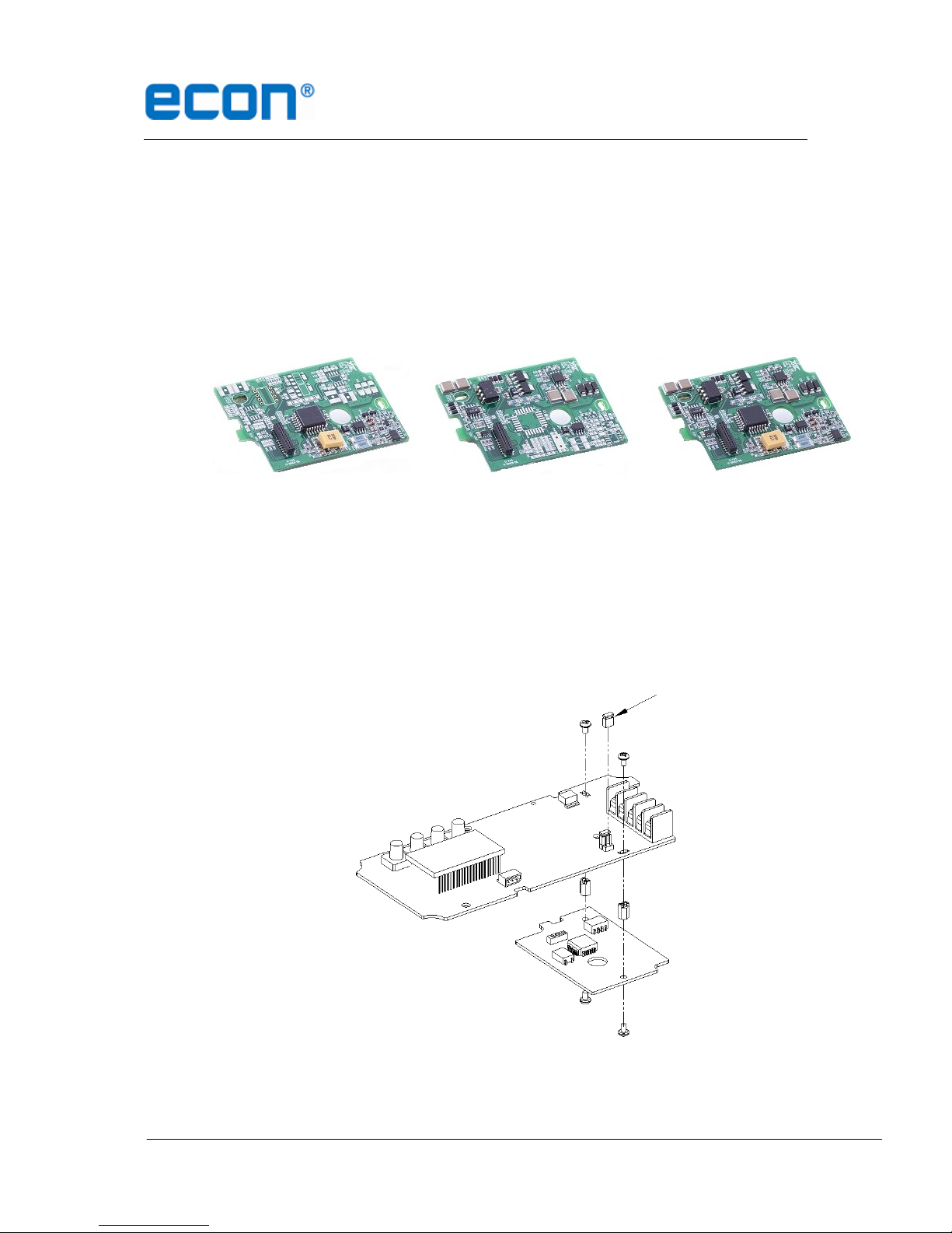
5.3 Option PCB Adjustment
By adding option sub-PCB, the positioner can have options.
There are 3 types of sub-PCB’s:
- HART®Protocol (HART) only
- Position Transmitter (PTM) only
- Position Transmitter (PTM) and HART®Protocol (HART)
HART only PTM only PTM + HART
Installation Steps
1. Open the cover and remove the main PCB from the positioner.
2. Mount support PCB and plug sub-PCB into main PCB connector.
.
** Option Jumper must be removed, when HART®option included sub-PCB is being mounted.
Option Jumper
Installation and Operating manual
Econ®Series 3300 Smart Valve Positioner www.eriks.com www.eriks.com
20
6 Operation
6.1 Safety
The following process will operate valve and actuator. Before proceeding with any
AUTO Calibration, please separate valve from the entire system, so AUTO Calibration
will not affect entire process.
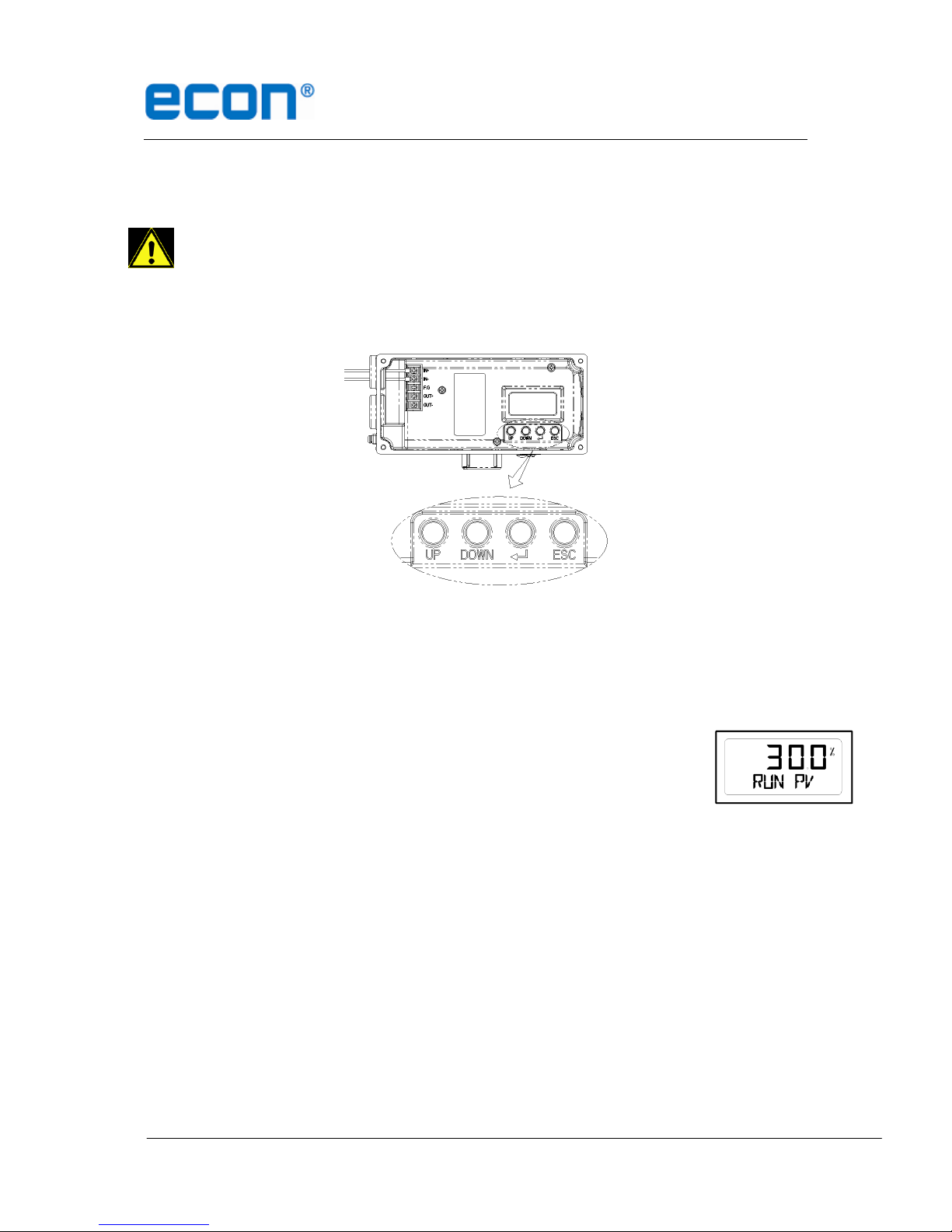
6.2 Button Description
The positioner has 4 buttons, and they perform various functions.
Fig. 11: <ENTER>: Enter to main and sub menus, and save
<ESC>: Return to previous menu
<UP> & <DOWN>: Move to next menu, and adjust.
6.3 Run Mode (RUN)
After connecting power to the positioner, Run Mode will appear on
positioner’s LCD screen within 6 seconds. “RUN”indicates that
the positioner adjusts the valve stroke according to the receiving
signal. There are six types of display message in “RUN”Mode.
1. Run PV: Process Value - valve stroke %
2. Run SV %: Set Value –input signal 0~100%
3. Run SV mA: Set Value –input signal 4~20mA
4. Run MV: Manipulate Valve –Motor Manipulate Value (digit)
5. Run Vel: Velocity –Current valve stem’s velocity (digit)
6. Run Err: Error –Difference between SV and PV (%)
To change display, push <ESC> + <UP> buttons at the same time. The display will change in the
order indicated above. If <ESC> + <DOWN> pushed, the order will appear in reverse order. By
pressing <ESC>, the display will return to “RUN”mode.
Other manuals for 3300 Series
1
This manual suits for next models
4
Table of contents
Other Econ Valve Positioner manuals

Popular Valve Positioner manuals by other brands


Samson
Samson 3730-3 ESD Mounting and operating instructions

Flowserve
Flowserve D20 Series Installation operation & maintenance

Westlock
Westlock ICoT PA Installation & operating manual

Baileigh Industrial
Baileigh Industrial RWP-55-1.0 Operator's manual

Samson
Samson TROVIS 3730-1 TRANSLATION OF ORIGINAL INSTRUCTIONS

KAUP
KAUP T 163SN operating manual