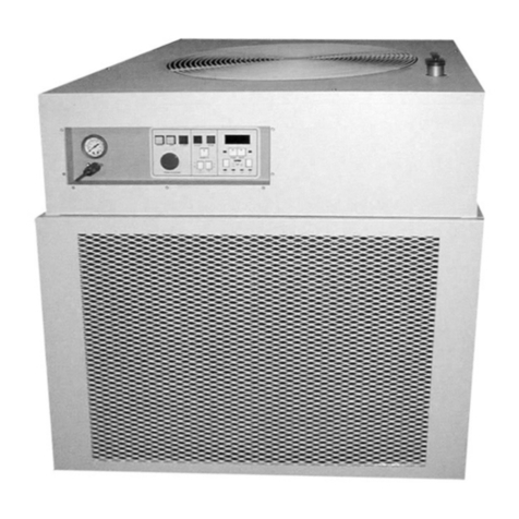
SP Scientific FTS FLEXICOOL IMMERSION COOLERS FC50 User manual

IMMERSION COOLERS FC50, FC100 OPERATOR’S MANUAL
FTS
S
YSTEMS
F
LEXI
C
OOL
IMMERSION COOLERS


Rev 001, 10/13 i
© SP Scientific 2013
Copyright © 2013 SP Scientific. All marks herein are used under license.
All brand or product names mentioned may be trademarks or registered trademarks of their respective
companies.
Part Number 100006437
Rev 001, 10/13
Original Instructions
The U.S. English version of this document is the original instructions.
All other languages are a translation of the original instructions.
SP Scientific
3538 Main Street
935 Mearns Road
815 State Route 208
Stone Ridge, NY 12484
USA
Warminster, PA 18974
USA
Gardiner, NY 12525
USA
(800) 251-1531
(800) 523-2327
(800) 431-8232
(845) 687-0071
(215) 672-7800
(845) 255-5000
SP Service
(877) 548-4666
SP Service Fax
(845) 687-0024
Website
http://www.spscientific.com/
This Immersion Coolers FC50, FC100 Operator’s Manual contains confidential and proprietary information of
SP Scientific and may be used only by a recipient designated by and for purposes specified by SP Scientific.
Reproduction of, dissemination of, modifications to, or the creation of derivative works from this Immersion
Coolers FC50, FC100 Operator’s Manual, by any means and in any form or manner, is expressly prohibited,
except with the prior written permission of SP Scientific. Permitted copies of this document must retain all
proprietary notices contained in the original.
The information in this document is subject to change without prior notice. Always confirm with SP Scientific
that you are using the most current version of this document. SP Scientific is free to modify any of its products
and services, in any manner and at any time, notwithstanding the information contained in this document.
THE CONTENTS OF THIS DOCUMENT SHALL NOT CONSTITUTE ANY WARRANTY OF ANY KIND,
EITHER EXPRESSED OR IMPLIED, INCLUDING BUT NOT LIMITED TO THE IMPLIED WARRANTIES OF
MERCHANTABILITY AND/OR FITNESS FOR A PARTICULAR PURPOSE OR GIVE RISE TO ANY LIABILITY
OF SP SCIENTIFIC, ITS AFFILIATES OR ITS SUPPLIERS.
The terms and conditions governing the use of this Immersion Coolers FC50, FC100 Operator’s Manual shall
consist of those set forth in written agreements with SP Scientific.

ii Rev 001, 10/13
© SP Scientific 2013
Important Symbols
WARNING! INJURY OR EVEN
DEATH MAY RESULT IF A
RECOMMENDATION MARKED
WITH THIS SYMBOL IS NOT
HEEDED.
CRUSH HAZARD. KEEP HANDS
CLEAR WHEN OPERATING DOOR.
ELECTRIC SHOCK DANGER! USE
APPROPRIATE CAUTION TO AVOID
INJURY OR DEATH.
CORROSIVE CHEMICAL. WEAR
SUITABLE GLOVES, SAFETY
GLASSES, AND PROTECTIVE
CLOTHING.
BURN DANGER! POTENTIALLY
HOT SURFACE. USE
APPROPRIATE CAUTION.
COLD BURN DANGER!
POTENTIALLY EXTERMLY COLD
SURFACE. USE APPROPRIATE
CAUTION.
WARNING! HAZARDOUS
MATERIAL/CONTACT HAZARD.
PROPERTY CAUTION! TO
PREVENT DAMAGE TO CHAMBER
EQUIPMENT AND/OR LOAD,
ADHERE TO PROCEDURES
MARKED BY THIS SYMBOL.
DO NOT STORE FLAMMABLE
MATERIALS IN CHAMBER.
PRACTICAL OPERATING TIP.
THESE RECOMMENDATIONS
STREAMLINE UNIT OPERATION
AND PREVENT COMMON
OPERATOR ERRORS.
ALWAYS WEAR APPROPRIATE
PERSONAL PROTECTIVE
EQUIPMENT (PPE) SUITED FOR
THE TASK YOU ARE PERFORMING.
EXPLOSIVE MATERIALS HAZARD!
KEEP OBJECTS AWAY FROM
HEAT.
Safety Warnings
Always transport the unit with care. Sudden jolts or drops may damage the refrigeration system.
Always observe all warning labels.
Always turn off the unit and disconnect the line cord from the available power source prior to performing anyservice or maintenance procedures.
Always turn off the unit and disconnect the line cord from the available power source prior to moving the unit.
Always operate, store and transport the unit in the upright position.
Never operate equipment with damaged line cords.
Never remove warning labels.
Never operate damaged or leaking equipment.

Rev 001, 10/13 iii
© SP Scientific 2013
Warranty Information
FTS Systems FlexiCool low temperature baths are warranted by SP Scientific to be free of defects in material and
workmanship when operated under normal conditions as specified in the instructions provided in this manual. Please
take this opportunity to locate the serial tag on your new FTS Systems FlexiCool and record the information below for
future reference. SP Scientific also recommends that you complete and return your unit’s warranty registration card.
Model Number
Serial Number
Part Number
Limited Warranty
SP Scientific (the “Company”) shall warrant each of its products against defects in material or workmanship for a period
of 12 months from the date of shipment provided that the product is used in a reasonable manner under appropriate
conditions and consistent with the applicable operating instructions.
The obligation of the Company shall be, at its option, to repair or replace, without charge any parts that prove to be
defective within the warranty period, if the purchaser notifies the Company promptly in writing of such defect. No
product shall be returned to the Company without prior approval of the Company.
This limited warranty shall cover the costs of parts and labor to repair or replace all defective product(s) at the Seller’s
factory. For all products installed by the Company and located within the Company service travel areas, this warranty
shall cover transportation charges to ship the product to and from the Company’s factory and/or the costs of travel,
room and board if the Company’s employees conduct repair at the Buyer’s location. In lieu of repair or replacement at
the Company’s factory, the Company may, in its discretion, authorize a third party to perform the repair or replacement
at the Buyer’s location, and at the Company’s sole expense.
The Company shall not be responsible for labor charges payable with respect to persons other than Company
employees. Replacement or repair of parts pursuant to this warranty shall not in any way extend the original warranty
period. The Company shall not be responsible for any unauthorized repairs, replacements or product modifications, nor
will it be responsible for any product failures resulting from such unauthorized repairs, replacements or product
modifications negligently or otherwise made by persons other than Company employees or authorized representatives
of the Company. The buyer shall assume transportation charges to ship the product to and from the Company’s factory
and the costs of travel, room and board if the Company’s employees conduct repair at the Buyer’s location within the
warranty period if the product was not installed by the Company’s and/or is not located within the Company’s service
travel areas.
THE COMPANY DOES NOT MAKE AND EXPRESSLY DISCLAIMS ANY WARRANTY OF MERCHANTABILITY OR
FITNESS FOR A PARTICULAR PURPOSE OR ANY OTHER WARRANTY, EXPRESSED OR IMPLIED, WITH
RESPECT TO THE SALE, INSTALLATION, DESIGN OR USE OF ITS PRODUCTS. ADDITIONALLY, THE
COMPANY SHALL NOT BE LIABLE FOR ANY CONSEQUENTIAL DAMAGES RESULTING FROM THE USE OF OR
ANY DEFECTS IN ITS PRODUCTS.
The Company’s employees are available to provide general advice to customers concerning the use of the Company’s
products; however, oral representations are not warranties with respect to particular products or their uses and may not
be relied upon if they are inconsistent with the relevant product specifications for the items set forth herein.
Notwithstanding the above, the terms and conditions set forth in the Company’s formal sales contracts shall be
controlling and supersede any inconsistent terms contained herein, and any changes to such contracts must be made
in writing and signed by an authorized executive of the Company.
WARNING! THE DISPOSAL AND/OR EMISSION OF SUBSTANCES USED IN CONNECTION
WITH THIS EQUIPMENT MAY BE GOVERNED BY VARIOUS FEDERAL, STATE OR LOCAL
REGULATIONS. ALL USERS OF THIS EQUIPMENT ARE URGED TO BECOME FAMILIAR
WITH ANY REGULATIONS THAT APPLY IN THE USERS AREA CONCERNING THE DUMPING
OF WASTE MATERIALS IN OR UPON WATER, LAND OR AIR AND TO COMPLY WITH SUCH
REGULATIONS.

iv Rev 001, 10/13
© SP Scientific 2013

Rev 001, 10/13 v
© SP Scientific 2013
Contents
Important Symbols...............................................................................................................................................ii
Safety Warnings...................................................................................................................................................ii
Warranty Information .......................................................................................................................................... iii
Contents.......................................................................................................................i
Introduction .................................................................................................................1
Overview..............................................................................................................................................................1
Key Features........................................................................................................................................................2
Key Benefits.........................................................................................................................................................2
Getting Started............................................................................................................3
Initial Inspection...................................................................................................................................................3
Lifting the FlexiCool .............................................................................................................................................3
Setup ...................................................................................................................................................................4
Ambient Conditions..............................................................................................................................................4
Air Flow Considerations.......................................................................................................................................5
Electrical Requirements.......................................................................................................................................5
IEC Protection - Class 1..................................................................................................................................5
Services and Utilities.......................................................................................................................................5
Installation............................................................................................................................................................6
System Preparation.........................................................................................................................................7
Operation....................................................................................................................9
Front Panel Display..............................................................................................................................................9
Basic Operation .................................................................................................................................................10
Start Up.........................................................................................................................................................10
Control...........................................................................................................................................................11
Powering Off..................................................................................................................................................11
Delivery Line......................................................................................................................................................11
Probes ...............................................................................................................................................................12
Sound Level.......................................................................................................................................................13
SOLO4848 Controller................................................................................................15
Overview............................................................................................................................................................15
Display and Keypad Identification and Use........................................................................................................15
PV Display.....................................................................................................................................................15

Contents
FTS Systems FlexiCool
vi Rev 001, 10/13
© SP Scientific 2013
SV Display.....................................................................................................................................................15
SET Button....................................................................................................................................................15
Rotate Button ................................................................................................................................................15
Up..................................................................................................................................................................16
Down.............................................................................................................................................................16
Auto Tuning...................................................................................................................................................16
Output 1, Output 2.........................................................................................................................................16
Alarm.............................................................................................................................................................16
Unit of Temperature (°C, °F)..........................................................................................................................16
Temperature-Controlled Operation....................................................................................................................16
Display and Indicators...................................................................................................................................16
Restarting......................................................................................................................................................16
Multiple Machine / Controller Setup ...................................................................................................................17
Connection Procedure...................................................................................................................................17
Controller Setup ............................................................................................................................................17
Monitoring Software Procedure.....................................................................................................................18
Maintenance .............................................................................................................19
Cleaning.............................................................................................................................................................19
Compressor Safeties .........................................................................................................................................20
Refrigerant Types and Properties..................................................................................................................20
Refrigeration System.....................................................................................................................................21
Appendix A: Temperature Calibration.......................................................................23
Appendix B: Changing Temperature Display ............................................................25
Appendix C: Troubleshooting....................................................................................27

Rev 001, 10/13 1
© SP Scientific 2013
Chapter
1
Introduction
Overview
THE FTS SYSTEMS FLEXICOOL IS NOT INTENDED FOR USE WITH
EXTREMELY FLAMMABLE FLUIDS SUCH AS ISOPENTANE (C5H12).
The FTS Systems FlexiCool FC50 and FC100 are mechanically refrigerated
Immersions Coolers that offer high heat removal and rapid cool down capabilities. The
FlexiCool meets the requirements for a variety of applications and features an optional
temperature controller that allows for programming and/or control from remote
locations.
The FTS Systems FlexiCool comes equipped with one (1) of three (3) standard probe
configuration that may be placed wherever direct cooling and heat removal from
ambient to -100 °C is required. These probes allow the unit to achieve maximum
efficiency through the direct expansion of refrigerant inside the probe, which
eliminates the need for a secondary medium or pumping.
The three (3) standard probe configurations are:
Cartridge Probe (P1) Flexible Probe (P2) Coil Probe (P4)
Note: For more information on the standard probes, refer to the Probes section of
Chapter 3: Operation. Custom probes are available upon request.
FC100
FC50

Introduction
FTS Systems FlexiCool
2 Rev 001, 10/13
© SP Scientific 2013
Key Features
Digital control with external RTD.
Choice of three (3) probe options.
Optional USB adapter, 2m cable and software for plug and play operation.
Mechanically refrigerated.
Key Benefits
Allows for accurate process control.
Allows cooling for a variety of applications.
Permits complete control of the machine from a PC and allows for datalogging
Eliminates costs and hazards associated with expendable refrigerants.

Rev 001, 10/13 3
© SP Scientific 2013
Chapter
2
Getting Started
Initial Inspection
Your FTS Systems FlexiCool immersion cooler was carefully packed and thoroughly
inspected before leaving the SP Scientific factory. However, in the unlikely event that
shipping damage has occurred, retain all packing material and contact your freight
carrier immediately.
DO NOT ACCEPT DAMAGED SHIPMENTS FROM A CARRIER WITHOUT A
SIGNED NOTIFICATION OF DAMAGES.
Upon receiving your shipment, inspect all contents of your equipment for damage.
Carefully remove the unit from the box taking care when handling the probe. Carefully
remove all packing material from the unit and inspect for visible damage. Check
packing material for small accessory items. Inspect the inside of the unit and related
parts for visible damage and leaks. Check for visible liquid at or near the base of the
unit.
If concealed damage or loss is discovered, contact the freight carrier immediately.
1
Keep all contents, packing material and related paperwork intact until a written report
is obtained.
Note: SP Scientific will cooperate in the matter of collecting your claim, but is not responsible
for the collection or free replacement of the material. When possible, replacement parts will be
shipped and invoiced to you, making them a part of your claim.
Lifting the FlexiCool
If no damage was discovered following the initial inspection of the FlexiCool, make
sure that two (2) individuals are available to safely lift and carry the unit using proper
lifting techniques (i.e., bending at the knees, not at the back). The FlexiCool should be
held beneath the front and rear, while keeping the unit level.
WARNING! THE FC100 WEIGHS APPROXIMATELY 70 LBS (32 KG) AND THE
FC50 WEIGHS APPROXIMATELY 50 LBS (23 KG). ALWAYS PRACTICE TEAM
LIFTING AND USE PROPER LIFTING TECHNQIUES WHEN MOVING HEAVY
EQUIPMENT.
1
“Concealed damage or loss”refers to damage or loss that does not become apparent until the merchandise has been
unpacked and inspected. Should damage or loss be discovered, you may make a written request for inspection by the carrier's
agent within 15 days of the delivery date. You may then file a claim with the freight carrier or SP Scientific, depending on the
terms of your shipment. If your shipment was “FOB Destination” file your claim with SP Scientific and include the inspection
report and any other supporting documents. If your shipment was “FOB Shipping Point” file your claim with the freight carrier
and include the inspection report and any other supporting documents.

Getting Started
FTS Systems FlexiCool
4 Rev 001, 10/13
© SP Scientific 2013
Setup The FTS System FlexiCool Immersion Cooler is designed for bench-top installation in
a laboratory environment. Your unit should be installed on a firm, level surface in a
location that is convenient for both operation and service.
NEVER PLACE THE UNIT IN AND AREA WHERE EXCESSIVE HEAT,
MOISTURE OR CORROSIVE MATERIALS ARE PRESENT.
Ambient Conditions
NEVER OPERATE THE FTS SYSTEMS FLEXICOOL IN AN AREA WITH AN
AMBIENT TEMPERATURE ABOVE 31 °C (88 °F).
This unit is designed for operation in a normal indoor environment (systems should
not be mounted outside or otherwise exposed to the elements). The environment
should be free from air containing large amounts of moisture, salt or sulfur.
For best low-temperature operation, consider that the ideal ambient temperature for
your FTS Systems FlexiCool is approximately 22 °C (71.6 °F). Higher ambient
temperatures will limit the system’s ability to achieve its ultimate low temperature.
Ambient Air Temperature Requirements
12 to 20 C (55 to 69 F)
Acceptable, but expect reduction.
21 to 24 C (70 to 75 F)
Ideal.
25 to 27 C (77 to 80 F)
Acceptable, but a reduction in the cooling capacity of the unit
is to be expected (i.e., about a 1% cooling capacity reduction
per degree above 25 °C (77 °F)).
28 to 30 C (82 to 86 F)
Expect reduced reliability. Warranty may be voided.
Over 31 C (Over 88 F)
Not Acceptable. Warranty will be voided.

FTS Systems FlexiCool
Getting Started
Rev 001, 10/13 5
© SP Scientific 2013
Air Flow Considerations
The FTS Systems FC50 and FC100 are equipped with an air-cooled refrigeration
system. Air is pulled from the left side of the unit to cool the refrigeration system
components and then exits the rear panel. When positioning your system, ensure that
it is located on a firm, level surface in an area that provides adequate air circulation.
Inadequate airflow will degrade the unit’s cooling capacity and in extreme cases may
result in compressor failure. A minimum of 4 inches (10.2 cm) of clearance on all
sides of the unit is required to ensure proper airflow and avoid damage to the
refrigeration system.
This equipment can add up to 3400 Btu/hr (1 kw) of heat to the room. Always ensure
that proper ambient temperature is maintained to ensure best performance.
Electrical Requirements
All 120 VAC / 60 Hz equipment is supplied with a 6 ft., 7 in (2 m) long power cord
terminated with a molded NEMA 5-15P plug.
All 220 VAC / 50 Hz equipment is supplied with a 9 ft., 10 in (3 m) long, un-terminated,
AWG 18-3 power cord. Both cords are detachable and have a molded IEC 60320
C-13 plug that attach to the machine.
Equipment rated with a nominal voltage of 120 VAC / 60 Hz should only be operated
from 113 to 127 VAC. Equipment rated with a nominal voltage of 220 VAC / 50 Hz
should only be operated from 211 to 240 VAC.
Note: Variances in frequency of ± 3 Hz are permitted.
IEC Protection - Class 1
This unit’s chassis is connected to earth ground through a 3-conductor mains cable.
Ensure that the AC outlet has corresponding ground and that the voltage and
frequency match the serial tag on the back of the unit.
Services and Utilities
The FTS Systems FlexiCool’s serial tag, which is located on the unit’s back panel,
provides the unit serial number, and electrical requirements. Ensure that the voltage,
phase, frequency and amperage listed on the serial tag match your facility’s available
power supply (e.g., as a minimum the power outlet you intend to use must meet the
requirements listed on the serial tag).
CAUTION! IF YOU ARE UNSURE ABOUT THE AVAILABLE ELECTRICAL
VOLTAGE SUPPLY IN YOUR FACILITY, CONSULT A QUALIFIED ELECTRICIAN.
Prior to connecting your FTS Systems FlexiCool to the available electrical supply,
ensure that the Main Power switch is in the Off position. You may connect the unit to
the available electrical supply at this time.
NEMA 5-15P

Getting Started
FTS Systems FlexiCool
6 Rev 001, 10/13
© SP Scientific 2013
Installation
Only qualified personnel should perform the installation of this unit. The voltage and
frequency requirements are specified on the serial tag on the rear of the unit.
Verify that the facilities voltage matches the requirement for the machine,which is printed on the serial tag on the rear of the machine.
The electric service wiring must be of a large enough wire gauge that thevoltage is maintained to the receptacle even when a full load is applied to the
receptacle. Additionally, the receptacle voltage should be measured while
that receptacle is under load.
Ensure the proper amperage circuit breaker is installed in the line and locatednear the equipment.
Plug in the line cord. Avoid the use of long extension cords, these cause asignificant power drop between the wall receptacle and the machine.
Note: For Lock Out / Tag Out plug the appropriate device into the line cord.
CAUTION! IF YOU ARE UNSURE ABOUT THE AVAILABLE ELECTRICAL
VOLTAGE SUPPLY IN YOUR FACILITY, CONSULT A QUALIFIED
ELECTRICIAN.

FTS Systems FlexiCool
Getting Started
Rev 001, 10/13 7
© SP Scientific 2013
System Preparation
Locate the provided pencil sensor (RTD).1.
Plug the pencil sensor (RTD) into the jack labeled SENSOR on the back of2. the unit.
Place the sensor so that the shaft is in contact with the fluid / vapor whose3. temperature is to be controlled.
Plug the unit into the power source.4.
Pencil Sensor (RTD)
plugged into
SENSOR jack
SENSOR Jack

Getting Started
FTS Systems FlexiCool
8 Rev 001, 10/13
© SP Scientific 2013

Rev 001, 10/13 9
© SP Scientific 2013
Chapter
3
Operation
CAUTION LOW TEMPERATURES: STAINLESS STEEL PROBES AND FLUIDS
IN CONTACT WITH THE PROBES CAN REACH EXTREMELY LOW
TEMPERATURES (E.G., -100 °C (-148 °F)). AVOID COLD BURNS BY NEVER
HANDLING STAINLESS STEEL PROBES OR FLUIDS WHEN THEY REACH
EXTERMLY LOW TEMPERATURES.
Front Panel Display
The front panel of the FlexiCool FC50 and FC100 (control) houses the main power
switch, cool indicator, process temperature controller and communication port. The
front panel of the FlexiCool FC50 or FC100 (no control) only features the main power
switch and cool indicator.
Cool Indicator
Main Power Switch
Temperature Controller
Communication Port

Operation
FTS Systems FlexiCool
10 Rev 001, 10/13
© SP Scientific 2013
Basic Operation
Start Up
Turn the main power switch to the ON position.1.
The controller will turn on and display the current process temperature and2. setpoint value.
Adjust the setpoint using the Up and Down buttons.3.
Press the SET button to accept the setpoint.4.
Up
Down
SET

FTS Systems FlexiCool
Operation
Rev 001, 10/13 11
© SP Scientific 2013
Control
When the system is running, use the Up and Down buttons ( ) to1. bring up the setpoint.
Press the button SET ( ) to accept the setting.2.
Powering Off
Toggle the main power switch to the OFF position.1.
The refrigeration will shut down and the display will be blank.2.
Unplug the unit.3.
Thoroughly clean and dry the probe head after each use.4.
Delivery Line
The FTS Systems FlexiCool has a delivery line that carries the refrigerant to the probe
and back. This flexible delivery line is made of corrugated stainless steel tubing with
several layers of insulation. Although this line is strong, it can be damaged to the point
of rupture if it is repeatedly bent too sharply or forcibly twisted. This line must remain
gas-tight in order to contain the refrigerant charge in the unit.
Never bend the delivery line more sharply than a 5-inch (12.7 cm) radius or a10-inch (25.4 cm) diameter.
Supporting the delivery line at one or more places is recommended to preventsagging or stressing the line.
Wide contact points on the supports are recommended to avoid compressingor degrading the internal insulation.
Adjusting the delivery line when it is cold may damage the insulation orstainless steel tubing, which may result in reduced performance.
Note: Do not move the delivery line when it is cold. Always turn the system off for at least
4 hours before making any adjustments to the placement of the delivery line.

Operation
FTS Systems FlexiCool
12 Rev 001, 10/13
© SP Scientific 2013
Probes The FTS Systems FlexiCool comes equipped with three (3) standard probe options:
Note: Custom probes are available upon request.
Cartridge Probe (P1 - Smooth Cylinder)
Well suited for cooling vapors.
Flexible Probe (P2 –Flexible Corrugated)
Corrugated, stainless steel flex-line makes this probe a versatile tool that can be used
for any number of applications.
Coil Probe (P4 –Smooth Coil)
Provides the highest surface area and allows maximum cooling of immersion baths.
The Cartridge Probe (P1 - Smooth Cylinder) and the Coil Probe (P4 –Smooth Coil)
are constructed of AISI Type 304 stainless steel heavy wall tubing and will withstand
hard usage and corrosion attack normal to this type of stainless steel. However, if the
probe comes into contact with other steel surfaces, the stainless surface will become
contaminated with free iron and rusting or pitting of the stainless surface may occur. If
such a condition is observed, treat with a 20% Nitric Acid solution by dipping or
brushing for approximately one hour. While cleaning, be sure not to dip the brazed
connection at the top of the coil in the acid solution. In severe cases, this pitting can
lead to perforation.
The Flexible Probe (P2 –Flexible Corrugated) is constructed of flexible AISI Type
316L stainless steel tubing. The Flexible Probe has no protective braid and is much
more susceptible to abrasion or puncture by a sharp object than the delivery line.
Please observe the following precautions:
Never reposition the Flexible Probe when it is cold.
Do not allow the Flexible Probe to drag on the floor or other rough surfaces.
Never wrap the Flexible Probe around the delivery line.
Never chip ice from the probe.
Never bend the Flexible Probe more sharply than a 1-inch (2.5 cm) innerradius or a 2-inch (5 cm) diameter.
Note: All the precautions outlined for the delivery line in the Delivery Line section of this chapter
apply to the Flexible probe.
This manual suits for next models
1
Table of contents
Other SP Scientific Chiller manuals
Popular Chiller manuals by other brands

CLIVET
CLIVET SCREWLINE3 MDE-SL3 Series Installation and operating manual

Johnson Controls
Johnson Controls YORK YK Series installation guide

Laird
Laird Nextreme quick start guide

Parker
Parker Hyperchill ICE076 user manual

Parker Hiross
Parker Hiross Hyperchill MAXI ICE460 user manual

Danfoss
Danfoss AR05 Operation instructions

York
York eco YCAS0685EB Wiring diagram

Colortronic
Colortronic AquaSnap 30RAN010-055 installation instructions

Castel MAC
Castel MAC T3 user guide

Ferroli
Ferroli RGA Series Technical manual

Bromic Heating
Bromic Heating Medifridge MED0220GD instruction manual

Carrier
Carrier AquaEdge 19DV series Operation and Troubleshooting