SP Blue Solo 80 User manual

Installation & Operation Manual
Sustainable Products Solar Water Heaters
MODEL: SP Blue Solo 80
Document : SP BLUE SOLO 80.2021.REV1.0
Sustainable Products & Treatment Systems
Solar Water Heaters
www.spswh.com
Sales & Service -Antonio Davila - 787-504-9927
Engineering- Paul Pauze PE- 787-438-0511
Mail: PO Box 1653, Trujillo Alto, PR 00977
Physical Address: Carr. 876, Km. 1.2, Bo. Cuevas Trujillo Alto PR

www.spswh.com 787-504-9927
SPSWH.com SP Blue Solo 80 installation manual Doc SP. SP Blue Solo 80.E.2021.REV1.0
2 |P a g e
Contents
Welcome...........................................................................................................................................3
Warnings...........................................................................................................................................3
Product Description: .........................................................................................................................4
3.1 System Diagram ............................................................................................................................5
3.2 Major Components & Specifications ............................................................................................6
3.3 Included Components with the Kit ...............................................................................................6
3.4 Components Not included- to Be Supplied by Installation Contractor ........................................7
3.5 Performance .................................................................................................................................7
Installation Instructions: ...................................................................................................................7
4.1 Orientation....................................................................................................................................7
4.2 Racking installation instructions:..................................................................................................7
4.3 Solar Thermal System Installation Instructions ............................................................................9
Startup Procedure...........................................................................................................................10
5.2 Maintenance...............................................................................................................................11
Operation Instructions:...................................................................................................................12
6.1 System Operation .......................................................................................................................12
6.2 Warranty.....................................................................................................................................13
Appendix .........................................................................................................................................15
7.1 OG-300 Label...............................................................................................................................15
7.2 Solar Tank Label ..........................................................................................................................15
7.3 Freeze Protection Label ..............................................................................................................16
7.4 Hot Fluid Label ............................................................................................................................16
7.5 Electrical Hazard Label................................................................................................................16
7.6 Electrical Diagram .......................................................................................................................18

www.spswh.com 787-504-9927
SPSWH.com SP Blue Solo 80 installation manual Doc SP. SP Blue Solo 80.E.2021.REV1.0
3 |P a g e
Welcome
Sustainable Products and Treatment Systems, a Puerto Rico company for over 40 years located in Trujillo
Alto, would like to thank you for your purchase of our World Class Blue-Wave line of Solar Domestic Hot
Water system. You are installing one of the highest quality, and most efficient Solar water heating
systems. SP Solar Water Heating products are designed specifically to meet the needs of Puerto Rico’s
tropical climate. The SP Blue Solo 80 and SP Blue Solo 80E systems will provide homeowners with
peace of mind that they will have purchased a high-performance system designed specifically for
residential applications in tropical locations. With its 2.92 m2 overall area, and 2.72m2 of solid surface
blue absorption collector area with a heavily insulated 80 gallon/300 L storage tank the SP Blue Solo 80
exceeds the performance requirements of Energy Star and SRCC certifications for Puerto Rico. The SP
Blue Solo 80 has the option to add a 3.5 kW electric element to the tank if required. If ordered in
advance, please specify the SP Blue Solo 80Emodel. If you have ordered the SP Blue Solo 80, the
electric element can be added to the tank as a retrofit, and the element is an option that must be special
ordered. With an SUEF of 12.03, and Solar Fraction per Puerto Rico Supplementary of 93%, the
electrical element would rarely be needed even during sustained periods of cloud cover.
Making Puerto Rico Sustainable is our goal, and with the purchase of the SP Blue Solo 80, or SP Blue Solo
80 -E option you have made the right choice for your family, and the environment.
Warnings
This Solar Thermal Domestic Hot Water system must be installed and serviced by trained professionals.
Failure to read and understand this manual could lead to sever injury or death. Please follow all
instructions carefully and completely. The installation of an anti-scaled rated mixing valve is strongly
recommended and required by code in most jurisdictions. Please check with certified plumbing contractor
about code requirements in your area.
DANGER! This system contains electrical connections that could be harmful if not
connected and maintained appropriately. Please ensure that all electrical
connections are installed and inspected by a training professional and that all
power to the unit is OFF prior to service and maintenance. Failure to comply
could result in injury or death.
DANGER! Fluid could be discharged at high temperatures or pressures, or
both. Fluids shall not be used that would change the original classification of
this system. Unauthorized alterations to this system could result in a health
hazard or hazardous conditions.
Figure 1 HOT WATER SCALD HAZARD
Figure 2 ELECTRICAL SHOCK HAZARD

www.spswh.com 787-504-9927
SPSWH.com SP Blue Solo 80 installation manual Doc SP. SP Blue Solo 80.E.2021.REV1.0
4 |P a g e
Product Description:
The SP Blue Solo 80 and SP Blue Solo 80 E are solar domestic hot water systems which use the sun’s
radiation to heat potable water for domestic use. These systems are thermosiphon systems which
means that they do not require the use of a pump to move the water, rather they rely on the natural
buoyance force of hot water to circulate water from the solar collectors to the storage tank. This
method of heating water is very cost effective, reliable, and efficient. The system is manufactured under
license by SP Treatment Systems and consists of ONE (1) SP BlueWave 29 collector which have a gross
area of 2.9m2(31.4 ft2) and a 300 L (80USG) storage tank. The E model (Optional) comes with a 3.5 kW
auxiliary electric heating element installed in the solar storage tank to provide additional heat. With
between 95% to 100% of hot water needs met by the system, (see OG300 Certificate Performance
details), the optional heating element should only be required for households with extensively high hot
water use –beyond the SRCC and Energy Star draw levels.
Both systems are SRCC OG-100, OG-300 & Energy Star certified
Contact information
SP Treatment Systems, Trujillo Alto Puerto Rico, spswh.com,787-504-9927
Model Name/Number
SP Blue Solo 80 / SP Blue Solo 80 E

www.spswh.com 787-504-9927
SPSWH.com SP Blue Solo 80 installation manual Doc SP. SP Blue Solo 80.E.2021.REV1.0
6 |P a g e
3.2 Major Components & Specifications
The system consists of the following components as seen in figure 1 & 2
3.2.1 One (1) SP Blue Wave 2.9 solar thermal collectors
a. Model: SP Blue Wave 29 (OG100 #10002144)
b. Dimensions, 2.92m2 (31.4 ft2), L=2006mm, W=1457mm, Height=85mm,
c. Absorber Volume/capacity –5 litres
d. Solar collectors can handle a max pressure of 16 bar (232 PSI)
e. System pressure will be mains pressure recommended below 8 bar (116 PSI)
3.2.2 One 300 L (80 USG) storage tank
a. Model: BLTG ECO 300
b. Fill weight –300 kg (661.4 lbs)
c. Storage tank has a maximum pressure rating of 10 bar (145 PSI)
d. System pressure will be mains pressure recommended below 8 bar (116 PSI)
3.2.3 Optional 3.5 kW Electrical heating element and thermostat (for E models only)
1
a. 3.5 electric heating element…….model # 107511-1016
b. Thermostat………………………………model # 108809-1017
c. Anode………………………………………model # 108803-0
d. Rubber Flange…………………………..model # 100506-875
e. Tube material: incoloy 800
f. 8.5 mm diameter with 298 mm protruding into the tank
g. Max current 20A, 240VAC, 1ɸ
h. Temperature range 10° - 85° C (50° - 185° F)
i. “Overload or Overcurrent protection of electrically operated components shall be
consistent with the maximum current rating of the device and with the provisions of
article 240, Chapter 2 of the National Electrical Code.”
3.2.4 6-point racking system
2
3.3 Included Components with the Kit
1. Temperature & Pressure relief valve, with ¾” coupling to tank
2. Stainless steel hoses and insulation to connect collectors to storage tank
3. Racking hardware (roof penetrations to be supplied by contractor)
4. Collector compression fittings –pipping fittings etc.
1
See Wiring diagram in appendix
2
See Installation section for racking details

www.spswh.com 787-504-9927
SPSWH.com SP Blue Solo 80 installation manual Doc SP. SP Blue Solo 80.E.2021.REV1.0
7 |P a g e
3.4 Components Not included- to Be Supplied by Installation Contractor
1. Pressure regulator value
2. Check Valve
3. Thermostatic mixing valve (Anti-scald
rated valve)
4. Isolation valves
5. Drain valve
6. Piping and associated fittings to connect
the system to mains water
7. Piping insulation/ UV covering
8. Temperature gauge as required
9. Pressure gauge- as required
10. Roof penetration hardware –3/8”
diameter with min 2” embedment with
O Hilti quick bolt-TZ, or
o Dewalt Power-Bolt
11. For optional EL model- 30A 240V
breaker and associated electrical
materials and Cable from electrical
panel to SDHW
Tank system
12. For optional E Model- 3.5kW heater
element- order from SPSWH.com
3.5 Performance
"The solar energy system described by this manual, when properly installed and maintained, meets the
minimum standards established by the SRCC. This certification does not imply endorsement or warranty
of this product by SRCC.”
Based on SRCC simulation data the System exceed the requirements of the CBDG program and Energy
Star for New Homes. The System has a solar fraction of 93% of the hot water produced by this system
will be provided by the sun. See the Energy Start certificate for performance details.
Installation Instructions:
4.1 Orientation
The solar thermal system shall be positioned with collectors facing due south whenever possible. It is
recommended that the slope of the collectors be equal to that of the latitude i.e., in Puerto Rico the
collectors should be at a tilt angle of approximately 18°. Failure to position the collectors facing south at
the proper angle could result in reduced system performance.
The location and orientation of the collectors shall be such that it is not shaded by external obstructions
or mutual shadowing. Any shading of the solar collectors must be limited with the collectors receiving a
full sun between the hours of 10 am and 4 pm. Any shading of the solar collectors will result in possible
reduction of system performance.
4.2 Racking installation instructions:
4.2.1 Roof & Wall Penetrations
Penetration of the building through which piping, or wiring is passed shall not reduce or impair the
function of the enclosure. Penetrations through walls or other surfaces shall not allow intrusion by
insects and vermin. Required roof penetrations shall be made in accordance with applicable codes and
also by practices recommended by the National Roofing Association.

www.spswh.com 787-504-9927
SPSWH.com SP Blue Solo 80 installation manual Doc SP. SP Blue Solo 80.E.2021.REV1.0
8 |P a g e
Installers must also be aware that the weight of the solar collectors, storage tank, racking and water
contained within is a considerable load, weighing approximately 400 kg (900 lbs). Consideration must be
taken to ensure the location selected for installation can handle this load as well as the weight of
installers and installation equipment. It is recommended that the installer review local code and contact
the local building department for confirmation of the structural integrity of any installation location. It is
also recommended that the homeowner consult with their insurance provider and inform them of the
installation.
See appendix for Engineering instructions for anchoring and PE stamp and detailed racking assembly
steps.

www.spswh.com 787-504-9927
SPSWH.com SP Blue Solo 80 installation manual Doc SP. SP Blue Solo 80.E.2021.REV1.0
9 |P a g e
4.3 Solar Thermal System Installation Instructions
4.3.1 Piping Installation
All pipes to and from the system must meet local building and plumbing codes for potable and hot water
and are supplied by the contractor. It is recommended that supply and return pipes from the home be
5/8” OD rigid copper. All pipes should be appropriately sloped (min 4°) to ensure the lowest point is the
bottom of the collector so that in the event of system decommissioning due to maintenance etc. the
water can be appropriately drained. See decommissioning and system diagram for additional details.
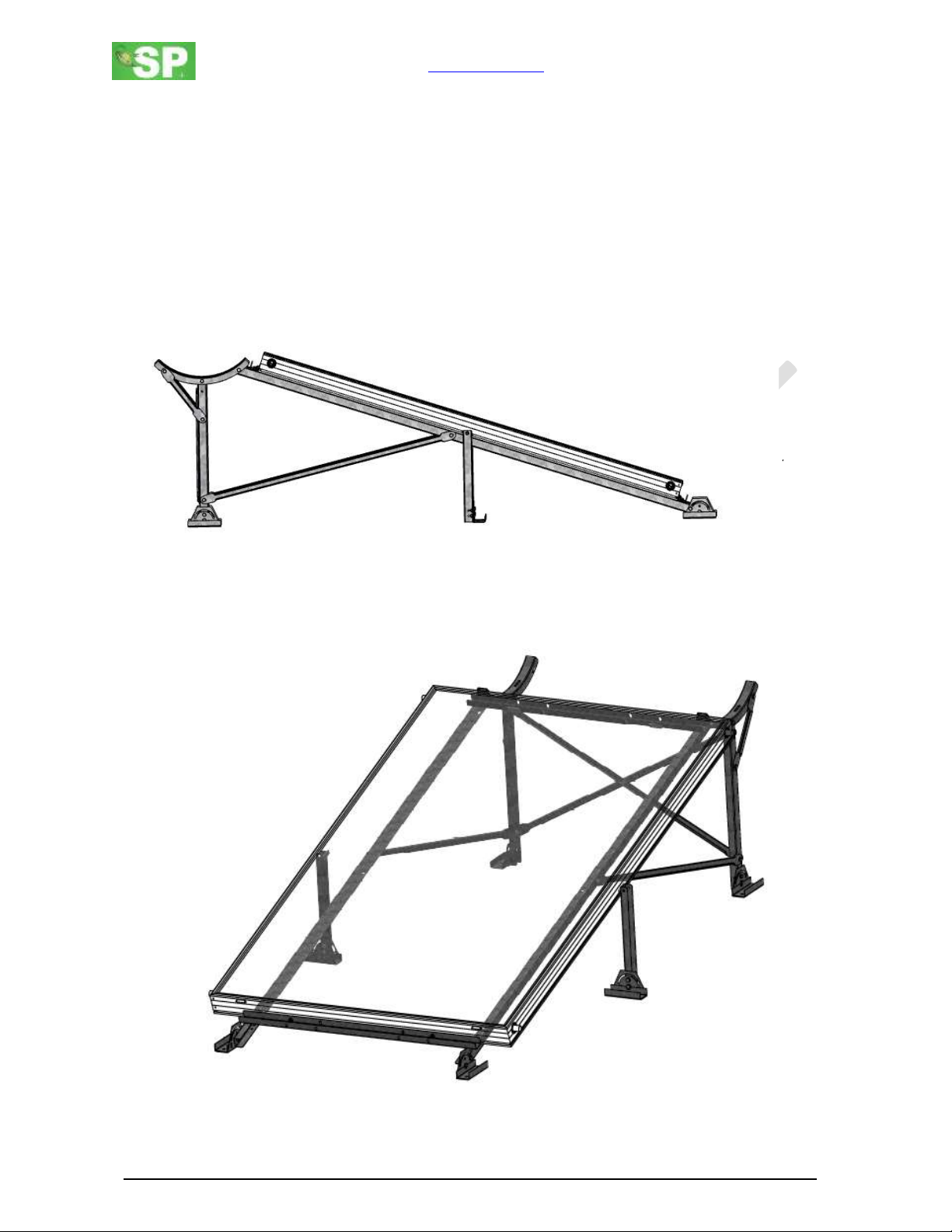
The piping and insulation on the solar system from the tank to the collectors and the collectors to the
tank is flexible stainless-steel hoses of size DN16 with 9 mm of insulation and protective UV coating
included which is included with the system. This hose is connected by following the steps in the pictorial
installation manual below.
There is a Danger during any draining of the system of scalding water at high pressure
being discharged. Caution must always be taken when discharging or draining the
system.
4.3.1.1 Piping Insulation
It is recommended that mains piping to the tank and return piping to the fixtures will be 5/8” OD copper
pipe and the recommended insulation will be ½” elastomeric foam R 3.4. Suitable protective cover of
the insulation must be installed to prevent damage from the elements. This can be a wrap or paint or
other means to protect the installation from the elements specifically moisture and UV.
4.3.2 Safety Relief Valve (Temperature & Pressure)
Safety relief valve dis-charge pipes shall be of rigid pipe that is approved for the temperature of the
system. The discharge pipe shall be the same diameter as the safety or relief valve outlet. Safety and
relief valves shall not discharge so as to be a hazard, a potential cause of damage or otherwise a
nuisance. Relief valves in partially filled collector loops capable of producing steam shall be discharged
to the outside of the structure. Where a relief valve discharges inside a structure or to the drainage
system, the installation shall conform to the plumbing code adopted by the authority having jurisdiction
or, in the absence of such code, the International Plumbing Code. Where a solar thermal system
component requiring a relief valve is located outside the structure, the termination shall be not more
than 6 inches (152 mm) above a splash block, a secured surface material or catchment method to pre-
vent damage.
4.3.3 Operating Indicators –Temperature gauges
It is recommended for the system the installation of two easy to read temperature gauges on the inlet
and outlet of the system, i.e., the cold mains water to the system and hot return water from the system.
These two gauges must be easily accessible by the system operator/owner and protected from the
elements. To determine whether the solar system is working, observe the temperature gauges when the
hot water is being used. The water returning from the collector on a sunny day at noon should be 75° -

www.spswh.com 787-504-9927
SPSWH.com SP Blue Solo 80 installation manual Doc SP. SP Blue Solo 80.E.2021.REV1.0
10 |P a g e
80° C (165° - 175°F) before the mixing valve. Due to the high temperatures, mixing valves are required in
most jurisdictions.
4.3.4 Isolation Valves
Isolations valves must be installed for installation of the solar thermal system. These valves will be ball
valves and will be on the incoming mains water line and supply line to the fixtures as seen in the system
diagram in Section 3.1.
4.3.5 Check Valve
A check valve must be installed for installation of the solar thermal system. The valves insure water does
not thermosyphon in reverse to the house. Failure to install the check valve will greatly reduce the
operation of the system. As seen in the system diagram in Section 3.1
4.3.6 Thermostatic Mixing Valve (Anti-Scald Valve)
A thermostatic mixing valve must be installed in most jurisdictions to minimize the risk of scalding from
extremely hot water supplied by the Solar system. The installation shall conform to the plumbing code
adopted by the authority having jurisdiction or, in the absence of such code, the International Plumbing
Code. As seen in the system diagram in Section 3.1.
4.3.7 Pressure Regulating Valve
A pressure regulating value must be installed in the system to ensure the equipment is protected from
pressure building in the system. Failure to install the pressure regulator valve can result in pressures
exceeding warranty of the components. Ensure Pressure is set below system limits. As seen in the
system diagram in Section 3.1.
4.3.8 Drain Valve
A drain valve should be installed in the system for ease of servicing. Location of the drain valve should
be at the lowest point in the system. As seen in the system diagram in Section 3.1.
Startup Procedure
Before system start up ensure that all installation instructions have been followed and all joints and
connections have been thoroughly tightened and checked for a tight seal. Ensure all electrical
connections have been installed and check by a qualified professional.
WARNING!
This system contains hot surfaces and fluids. Please exercise extreme caution during start up,
maintenance and decommissioning.
•Avoid touching any surface before taking its temperature as pipes and surfaces of
collector and tank may be hot.
•Prior to draining any fluid ensure that fluid can be discharged to a safe
location.
•Fluid may be extremely hot and under high pressure. In certain circumstances there may even
be steam in the system.
•When working near the electrical connection ensure it is turned off at the
breaker. Ensure that all electrical connections are secure and have been
installed by a trained professional.
This system is intended for use with fresh, potable water only. No other fluid shall be used that would
change the original classification of this system. Unauthorized alterations to this system could result in
a hazardous health condition.

www.spswh.com 787-504-9927
SPSWH.com SP Blue Solo 80 installation manual Doc SP. SP Blue Solo 80.E.2021.REV1.0
11 |P a g e
1. Ensure that all electrical connections are OFF, secure, and not exposed to elements or potential
leaks.
2. If start up is during the day please ensure the collectors are covered so as not to introduce cold
water into a hot collector. This could flash to steam cause scalding and damage to the system.
3. Open pressure relief valve to vent the storage tank to atmosphere.
4. Open the mains water line and begin filling the tank/collectors.
5. Once water starts coming out of pressure relief valve close valve and pressurise system.
6. Check each of the connections for leaks.
7. Remove covering from solar collectors.
8. Set mixing valve to desired temperature.
9. Turn electrical element on and set to desired temperature. (EL models only)
10. Ensure pressure relief valve is closed and is piped to a safe location as it may operate in over
temperature conditions causing hot water to be expelled and high pressure.
5.1.1 Expected Temperatures
During normal operation, the system will experience temperature on the inlet and outlet approximately:
-Inlet temperatures to the collector avg 55°- 60°C (130°-140°F)
-Outlet temperatures to the storage tank avg 75° - 80° (165° - 175°F)
5.2 Maintenance
5.2.1 Solar Collector Cleaning
The solar collectors do not require any maintenance; however, annual checks of the glass and
connections should be made to ensure there are no leaks, cracks etc. At this time, the glass can be
cleaned with a mild detergent if needed.
5.2.1 Hardware
It is recommended that all hardware is checked and tightened annually and/or after any sever weather.
5.2.2 Scale prevention in solar collectors
The solar collectors need to be flushed out using descaling solution once a year to ensure performance
and reliability. This is due to the fact that potable water is being heated directly in the collector and the
presence of CaCO3 (Calcium Carbonate) which precipitates out of water at temperatures above 50°C
(122°F) and can reduce heat transfer, lower flow rates and cause system failure if not treated. Failure to
follow these recommendations will void manufacturer warranty.
1. Isolate tank and shut off mains water.
2. Turn off electric connection to the system if applicable.
3. Cover the collectors to prevent heating descaling solution.
4. Remove the inlet and outlet connections to the collector using crescent wrench.
5. Using a descaling solution or other chemical for removing CaCO3 connect a hose to the inlet and
outlet connections.
6. Using a small circulating pump circulate descaling solution through the collectors for minimum
30 mins.

www.spswh.com 787-504-9927
SPSWH.com SP Blue Solo 80 installation manual Doc SP. SP Blue Solo 80.E.2021.REV1.0
12 |P a g e
7. After minimum 30 mins replace descaling solution with fresh water and flush the collectors for
an additional 5 mins
8. Replace inlet and outlet connections.
9. Open mains water.
10. Remove cover from collectors.
11. Connect electrical element if applicable.
*To avoid possible burns or scalding due to hot fluid or pipes it is recommended that you conduct
maintenance on overcast day, morning, or evening when the sun it not strong.
5.2.3 Scale prevention in the storage tank
In order to prevent sale formation in the storage tank it should be drained one a year and the
magnesium anode replaced if it has lost more than 50% of its total mass or is completely covered in lime
scale or as necessary based on water quality. Electrical element and connections should be check at this
time to ensure no undue build up of scale.
5.2.4 Extended Absence
In the event the system is unused for an extended period i.e., more than one week and less than on
month, it is recommended that in the EL model the electrical breaker be turned off to conserve power. If
the system is going to be left unattended for longer than one month with no use it is recommended to
turn off the electric element and drain the system. This can be done by turning off the mains water and
opening the drain valve.
Danger! When draining the system water could be very hot. Caution must be taken when opening
drain valve and touching pipes.
Warning! Please exercise caution when turning on/off electrical power. If unsure call qualified
electrical contractor
5.2.5 Decommissioning
Steps for decommissioning the system
1. Turn of the breaker to the electrical element when applicable.
2. Close isolation valves and ensure no water is entering or leaving the system.
3. Open the drain valve - Be Careful as water may be hot.
4. Loosen fittings around base of collector (Be Careful as water may be hot) and drain collectors.
5. Retighten fittings on the collector and leave drain valve open.
Operation Instructions:
6.1 System Operation
The system operates using fresh potable water which fills the tank and collectors. As the sun’s radiation
hits the collectors it turns that radiation into heat which heats the water in the collector tubes. As this
water is heated it becomes less dense and rises into the storage tank and is replaced by the denser, cold

www.spswh.com 787-504-9927
SPSWH.com SP Blue Solo 80 installation manual Doc SP. SP Blue Solo 80.E.2021.REV1.0
13 |P a g e
water at the bottom of the tank. The cycle repeats itself until the tank is full of hot water or the sun goes
down. There is an optional 3.5 kW electric heating element available for special order that can assist
heating the water in the tank if required. The electric heater option has to be specified if required. Its
not supplied in our standard SP Blue Solo 80 system.
The working fluid in this system is fresh water. No other fluid is authorized to be used in the system. If
any other fluid is used it could cause serious damage and or harm to the system and occupants.
6.1.1 Freeze Protection
This system is not designed to handle freezing temperatures and should not be installed in any location
that sees freezing temperatures at any point during the year. Should freezing conditions occur after
installation it is recommended to turn off the electrical power to the unit at the breaker and drain the
system and any external pipes completely that may be exposed to freezing temperatures. See
decommissioning section for more details on how to drain the system.
Danger! When draining the system water could be very hot. Caution must be taken when opening
drain valve and touching pipes.
Warning! Please exercise caution when turning on/off electrical power. If unsure call qualified
electrical contractor
6.2 Warranty
The system is covered by a manufacturers warranty in accordance with Energy Star Solar Water Heaters
certification criteria.
6.2.1 The manufacturer offers the following warranties:
•10 years on the collectors*
•6 years on the sealed system*
•1 year on the electrical components of the tank
•1 year for parts
6.2.2 The Warranty Does NOT Cover
•Cracked or broken glass of the solar panel
•The magnesium rod in storage tank
•Damages to the electrical components due to scale caused by poor water quality
•Damages to the safety valves due to scale caused by poor water quality
•Damage to the absorber, including piping, absorber sheet etc. due to poor water quality
•Damage to the selective surface due to moisture and humidity
•Damages as a result of modifications to the system by unauthorized personnel
•Damages from extreme operating conditions and external factors, fire, vandalism, extreme
weather events, etc.
•Labour, supplementary materials, travel expenses and shipping

www.spswh.com 787-504-9927
SPSWH.com SP Blue Solo 80 installation manual Doc SP. SP Blue Solo 80.E.2021.REV1.0
14 |P a g e
6.2.3 Instructions and conditions of the warranty:
•Installation must be in accordance with the instructions of the official manufacturer's
installation and operation manual from authorized personnel, certified by the manufacturer
•All repairs or maintenance must use spare parts approved by the manufacturer
•*For the proper operation of the system, the water should be potable and have a low mineral
content and be serviced annually by flushing the system to prevent mineral buildup.
•For the proper operation of the tank or the solar panel and prevention from damage, it is
necessary to examine the safety valve every year (6 months in areas of hard water) and in case
they have become clogged by scale or damaged in any way, they must be replaced immediately
6.2.4 Warranty Remarks:
•Any damage to the glass must be assessed and remedied immediately, such as cracks etc. or else
the potentials for damage to the absorber and loss of system performance
•Any superficial discolouration of the absorber may reduce panel efficiency slightly but will not
damage the system and is not cause for concern
•Any discolouration or corrosion of the racking and support base does not impact the structural
integrity of the racking and is not cause for concern
•Any discolouration or corrosion of the storage tank jacket (outer casing) does not impact the
structural integrity of the storage tank and is not cause for concern
•The water inside the tank should not exceed 95°C (203°F) and pressure of 10 bar (145 PSI)
•Warranty does not cover the cost of labour or shipping
•Warranty is only valid with signed and stamped invoice by the customer and manufacturer
6.2.5 Warranty and Service Claims
•Contact installer of the SP Blue Solo 80 or 80E system.
•If the installer is not available contact SP Solar Water Heaters –www.spswh.com
o787-504-9927

www.spswh.com 787-504-9927
SPSWH.com SP Blue Solo 80 installation manual Doc SP. SP Blue Solo 80.E.2021.REV1.0
15 |P a g e
Appendix
7.1 OG-300 Label
Manufacturer’s name
SP Treatment Systems
Model Name/number
SP Blue Solo 80
System listing number and third-party certification agency
30004362 SRCC OG-300
Collector listing number, third-party certification agency,
and quantity
SP Blue Wave 29, SRCC
10002144 OG-100
X1 collectors
Heat transfer fluid and concentration range
Fresh Water
Storage tank volume
300 L (80 USG)
Expansion tank volume
NA
Relief valve specification and setpoint
93°C - 99°C & 850 kPa
(199°F –210°F) & 123 PSI
Maximum water supply pressure
8 bar (116 PSI)
Maximum solar loop pressure
16 bar (232 PSI)
Backup energy rating. Include phase/volts/amps
3500 W 1P/240V/20A
Installation date field
(to be entered by the installer in the field)
7.2 Solar Tank Label
The maximum operating temperature and pressure for the solar water tank are:
Pressure:
10 bar/145 PSI
Temperature:
100°C/212°F

www.spswh.com 787-504-9927
SPSWH.com SP Blue Solo 80 installation manual Doc SP. SP Blue Solo 80.E.2021.REV1.0
16 |P a g e
7.3 Freeze Protection Label
This system is NOT freeze protected and should not be installed in any location where freezing is
possible. Should freezing temperatures occur, turn off the electrical element at the breaker and drain
the system immediately. Failure to do so could cause severe damage to the system and void the
warranty. See Decommissioning instructions in the installation manual for how to drain the system.
7.4 Hot Fluid Label
DANGER! Fluid could be discharged at high temperatures or pressures, or
both. Fluids shall not be used that would change the original classification of
this system. Unauthorized alterations to this system could result in a health
hazard or hazardous conditions.
7.5 Electrical Hazard Label
DANGER! This system contains electrical connections that could be harmful if not
connected and maintained appropriately. Please ensure that all electrical connections
are installed and inspected by a training professional and that all power to the unit is
OFF prior to service and maintenance. Failure to comply could result in injury or
death.

www.spswh.com 787-504-9927
SPSWH.com SP Blue Solo 80 installation manual Doc SP. SP Blue Solo 80.E.2021.REV1.0
17 |P a g e
This product certified by:
Solar Rating & Certification
Corporation™
www.Solar-Rating.org
SP Treatment Systems Inc.
P.O. Box 1653
Trujillo Alto, 00977 Puerto Rico
SPSWH.COM
Solar Energy
Factor (SUEF)
SRCC Cert. No.
Model No.
12.09
30004362
SP Blue Solo 80 / SP Blue Solo 80E
The installed system is marked above

www.spswh.com 787-504-9927
SPSWH.com SP Blue Solo 80 installation manual Doc SP. SP Blue Solo 80.E.2021.REV1.0
18 |P a g e
**Please note this table MUST be on a single page with no other content. If the SRCC certification
changes due to private labeling then the updated table must be inserted here.**
7.6 Electrical Diagram
Table of contents
Popular Water Heater manuals by other brands

Gorenje
Gorenje GB 30 E5 Instructions for use

Siemens
Siemens BK 52100 Operating and installation instructions

Heatrae Sadia
Heatrae Sadia Aquatap installation guide

Xylem
Xylem CLEGHORN WARING CW385 manual

A.O. Smith
A.O. Smith GPS-75 instruction manual

Laars
Laars Everhot IGE-199R Series Installation and operating instruction manual

STIEBEL ELTRON
STIEBEL ELTRON Accelera 300 Operating and installation

Kenmore
Kenmore 153.337162 owner's manual

Kärcher
Kärcher HWE 4000 Original instructions

ThermoFlow
ThermoFlow Mini Pro Series installation guide

JFD
JFD WHE - 3 Operation and maintenance manual

Solahart
Solahart SOLAR WATER HEATERS owner's manual