Spacelabs 90207 User manual

Ambulatory Blood Pressure
Monitors
90207/90217
Operations Manual
070-0137-03Rev. F

Copyright 2002 Spacelabs Medical, Inc.
All rights reserved. Contents of this publication may not be reproduced in any form without the written permission of Spacelabs
Medical, Inc. Products of Spacelabs Medical are covered by U.S. and foreign patents and/or pending patents. Printed in U.S.A.
Specifications and price change privileges are reserved.
Spacelabs Medical considers itself responsible for the effects on safety, reliability and performance of the equipment only if:
• assembly operations, re-adjustments, modifications or repairs are carried out by persons authorized by Spacelabs
Medical, and
• the electrical installation of the relevant room complies with the requirements of the standard in force, and
• the equipment is used in accordance with the operations manual.
Spacelabs Medical will make available, on request, such circuit diagrams, component part lists, descriptions, calibration instructions
or other information which will assist appropriately qualified technical personnel to repair those parts of the equipment which are
classified by Spacelabs Medical as field repairable.
Spacelabs Medical, Inc.
15220 N.E. 40th Street
P.O. Box 97013
Redmond, WA 98073-9713
U.S.A.
Telephone: 425-882-3700
Fax: 425-885-4877
Telex: 4740085 SPL UI
Spacelabs Medical Products Pty. Ltd.
Macquarie View Estates
Unit 1, 112-118 Talavera Road
North Ryde, N.S.W. 2113
AUSTRALIA
Telephone: 61-2-9878-6644
Fax: 61-2-9878-4820
Spacelabs Medical Products GmbH
Jochen Rindt Straße 25
1230 Vienna
AUSTRIA
Telephone: 43-1-616 52 37
Fax: 43-1-616 52 37-11
Spacelabs Medical B.V.
Airport Boulevard Office Park
Bessenveldstraat 25A
1831 Diegem
BELGIUM
Telephone: 32 2 7164026
Fax: 32 2 7164114
Spacelabs Medical Products, Ltd.
151 Superior Boulevard, Unit 1
Mississauga, Ontario L5T 2L1
CANADA
Telephone: 905-670-5880
Fax: 905-670-5883
Spacelabs Produits Medicaux Ltée
6030 rue Vanden Abeele
St. Laurent, Quebec H4S 1R9
CANADA
Telephone: 514-335-2669
Fax: 514-335-1042
CORPORATE OFFICES
Spacelabs Medical Instruments
(Tianjin) Co. Ltd.
6th Floor, Wang Jing Building
9 Wang Jing Zhong Huan South Road
Chaoyang District, Beijing 100015
CHINA
Telephone: 86-10-6438 1705
Fax: 86-10-6438 1707
Authorized EC Representative:
Spacelabs Medical Sarl
6, Allée des Saules
Europarc
94042 Créteil Cedex
FRANCE
Telephone: 33 (0) 1 45.13.22.44
Fax: 33 (0) 1 45.13.22.00
Spacelabs Medical GmbH
Justus-Liebig-Straße 3
41564 Kaarst
GERMANY
Telephone: 49-(0)2131-92670
Fax: 49-(0)2131-926721
Spacelabs Medical Limited
Suite 901 Tower 1
China Hong Kong City
33 Canton Road, Tsimshatsui
Kowloon
HONG KONG
Telephone: 852-2376-1370
Fax: 852-2376-2502
Spacelabs Medical, Inc.
C/O Impulse Business Club
F-22 South Extension Part 1
New Delhi 110049
INDIA
Telephone: 911 1464 5002
Fax: 911 1464 5007
Spacelabs Medical S.r.l.
Via Montecatini, 13
20144 Milano
ITALY
Telephone: 39-(0)-2/48958203
Fax: 39-(0)-2/48958204
Spacelabs Medical Ltd.
2F-3, No. 161. Sung Te Road
Taipei, Taiwan R.O.C.
TAIWAN
Telephone: 8862-2759-7228
Fax: 8862-2759-9060
Spacelabs Medical B.V.
Ringveste 9 A
3992 DD Houten
THE NETHERLANDS
Telephone: 31-(0)-30-638 5050
Fax: 31-(0)-30-638 5059
Spacelabs Medical Ltd.
Eskdale Road
Winnersh Triangle, Wokingham
Berkshire RG41 5TS
UNITED KINGDOM
Telephone: 44-1189-448411
Fax: 44-1189-448006
C
AUTI
O
N:
• US Federal law restricts the devices documented herein to sale by, or on the order of, a
physician.

i
Chapter Page
1Contents
Contents
Operation
Overview . . . . . . . . . . . . . . . . . . . . . . . . . . . . . . . . . . . . . . . . . . . . . . . . . . . . . . . . . . . . . . . . 1-1
Preparing the Patient and Precautions for Use . . . . . . . . . . . . . . . . . . . . . . . . . . . . . . . . . . .1-8
Data Transfer and Reports . . . . . . . . . . . . . . . . . . . . . . . . . . . . . . . . . . . . . . . . . . . . . . . . . 1-12
Event Codes . . . . . . . . . . . . . . . . . . . . . . . . . . . . . . . . . . . . . . . . . . . . . . . . . . . . . . . . . . . . 1-14
Accuracy
Checking Accuracy . . . . . . . . . . . . . . . . . . . . . . . . . . . . . . . . . . . . . . . . . . . . . . . . . . . . . . . .2-1
Troubleshooting
Problem Solving Checklist. . . . . . . . . . . . . . . . . . . . . . . . . . . . . . . . . . . . . . . . . . . . . . . . . . .3-1
Servicing . . . . . . . . . . . . . . . . . . . . . . . . . . . . . . . . . . . . . . . . . . . . . . . . . . . . . . . . . . . . . . . .3-2
Symbols


Spacelabs Medical is committed to providing comprehensive customer support beginning with your initial inquiry through
purchase, training, and service for the life of your Spacelabs Medical equipment. If you need our help along the way, we
offer these guidelines for fast, efficient response.
Acquiring Equipment
Sales Representative
800-522-7025 (U.S.A.)
or call your local office
To discuss your monitoring or clinical information
needs, to schedule product demonstrations, to order
equipment, or to schedule in-service education
Delivery Information
800-251-9910 (U.S.A.)
or call your local office
To find out when you can expect delivery of your
Spacelabs Medical equipment
Supplies Products
800-223-6467 (U.S.A.)
or call your local office
To order compatible supplies and accessories for your
equipment
Getting Started
Sales Representative
800-522-7025 (U.S.A.)
or call your local office
To arrange in-service education sessions
Answering Other Needs
Clinical Applications
800-522-7025 (U.S.A.) or 425-882-3700
or call your local office
To answer specific questions on arrhythmia products
and clinically related issues
First Call™ National Dispatch Center
800-522-7025 (U.S.A.)
800-942-7968 (Canada)
To call for service or to contact your assigned customer
service representative
Technical Support - Monitoring/Anesthesia
800-522-7025 (U.S.A.) or 425-882-3700
or call your local office
For technical support of all Ultraview®Care Network™
monitoring products and anesthesia products
Technical Support - Intesys Clinical Information Systems
800-210-0247 (U.S.A.) or 425-882-3700
or call your local office
For technical support of BirthNet®, Caremaster®,
Chartmaster®, QuIC, and WinDNA®products
Service Parts Department
800-547-8805 (U.S.A.) or 425-867-2039
or call your local office
For parts ordering and pricing information
Service Training Department
800-251-9910 (U.S.A.)
or call your local office
To arrange training of hospital biomedical and
anesthesia personnel
Regional Service Manager
800-522-7025 (U.S.A.)
800-942-7968 (Canada)
or call your local office
To obtain answers to general questions concerning
service issues and service contracts
Contacting Your Local Offices Outside the U.S.
Mississauga, Ontario
Canada
905-670-5880
Mönchengladbach
Germany
49-2161-8209-0
Kowloon
Hong Kong
852-2376-1370
Taipei
Taiwan
8862-2759-7228
Créteil
France
33 (0)1 45.13.22.44
Vienna
Austria
43-1-616 52 37
Milano
Italy
39-0-2/48958203
Beijing
China
86-10-6438-1705
Wokingham
Berkshire, U.K.
44-1189-448411
New Delhi
India
911 1464 5002
Diegem
Belgium
32 2 7164026


1-1
Contents
Overview . . . . . . . . . . . . . . . . . . . . . . . . . . . . . . . . . . . . . . . . . . . . . . . . . . . . . . . . . . . . . . . . . . . . . . . . . . . . . . . .1
Replacing the Batteries . . . . . . . . . . . . . . . . . . . . . . . . . . . . . . . . . . . . . . . . . . . . . . . . . . . . . . . . . . . . . . . . . . . . .2
Initializing the Monitor . . . . . . . . . . . . . . . . . . . . . . . . . . . . . . . . . . . . . . . . . . . . . . . . . . . . . . . . . . . . . . . . . . . . . .3
Preparing the Patient and Precautions for Use . . . . . . . . . . . . . . . . . . . . . . . . . . . . . . . . . . . . . . . . . . . . . . . . . . .8
Patient Instructions. . . . . . . . . . . . . . . . . . . . . . . . . . . . . . . . . . . . . . . . . . . . . . . . . . . . . . . . . . . . . . . . . . . . . . . .11
Data Transfer and Reports. . . . . . . . . . . . . . . . . . . . . . . . . . . . . . . . . . . . . . . . . . . . . . . . . . . . . . . . . . . . . . . . . .12
Cleaning . . . . . . . . . . . . . . . . . . . . . . . . . . . . . . . . . . . . . . . . . . . . . . . . . . . . . . . . . . . . . . . . . . . . . . . . . . . . . . . .12
Event Codes. . . . . . . . . . . . . . . . . . . . . . . . . . . . . . . . . . . . . . . . . . . . . . . . . . . . . . . . . . . . . . . . . . . . . . . . . . . . .14
Operation
Overview
The Spacelabs Medical Models 90207 and 90217 Ambulatory Blood Pressure (ABP) monitors are small,
lightweight battery-powered units designed to take blood pressure and heart rate measurements for 24 or 48
hours, or for longer periods of time.
These measurements are recorded in the monitors and may be transferred to an ABP Analysis System
(FT1000A/FT2000A or equivalent), the PC Interface, the Base Station, or a Report Generator for data analysis,
report printing, and archiving.
Each monitor and a base station can operate in a direct connect mode (when both units are in the same location)
or in a remote connection mode (using modems).
ABP Monitor
The monitors have the following features:
•4-digit LCD display
•Battery powered
•Serial communications port
•Power ON/OFF switch
•Reading START/STOP button
•Blood pressure cuff
The monitors are carried in pouches that are strapped and/or belted to the side of the patient. Blood pressure and
heart rate measurements are taken using a blood pressure cuff attached to the patient's arm. This information is
recorded in the monitors and can be transferred over a modem link or by direct connection between the monitors
and one of the ABP analysis systems.
The monitors can be programmed to either activate or deactivate the following features:
•Display the cuff pressure at each bleed step
•Display the systole, diastole, and heart rate at the end of each measurement
•Bleed to 40 mmHg rather than stopping at the diastolic value
•Beep before and after each reading

90207/90217 ABP Monitors
1-2
Front Panel
The 90207 and 90217 front panels include the LCD display, cuff hose connector, and a
START/STOP switch.
Rear Panel
The rear panels of both monitors contain program input and data output communication ports. On
the 90207 the power ON/OFF switch is also located on the rear panel. On the 90217 the ON/OFF
switch is located on the top panel.
Replacing the Batteries
“AA”batteries provide the main power source for the monitors. The 90207 uses four batteries, and
the 90217 uses three. These batteries should be replaced or recharged before the start of each
patient monitoring. Use either alkaline or NiCad batteries.
In the 90207, a lithium battery (P/N 146-0008-XX) is used to back up the monitor memory and
should be replaced periodically. The 90217 backup battery should not require replacement.
Main Battery Replacement
1. Turn the monitor off, and remove the door over the battery compartment.
2. Replace the AA alkaline or NiCad batteries, being careful to observe polarities.
3. Gently replace the battery cover and secure the latch.
4. Turn the monitor power switch on. Check that the LCD display is on. If there is no display, turn
the monitor off and review the problem-solving checklist in Troubleshooting in Chapter 3.
!•if the main “AA”batteries must be replaced during patient monitoring, this
replacement must be accomplished within one minute to ensure successful
resumption of the test (90207 only).
C
AUTI
O
N:
•The monitor will not operate if the alkaline, nickel cadmium, or lithium
batteries are incorrectly installed. If the monitor is going to be stored for
an extended period of time, remove the batteries to prevent the possibility
of leakage or discharge.
•Spacelabs Medical is not responsible for product damage incurred as a
result of AA battery leakage. In the event your unit has been damaged by
a leaking battery, contact the battery manufacturer for any recoverable
repair or replacement costs. Spacelabs Medical will assist you in
determining those costs

Operation
1-3
Lithium Battery Replacement (90207 only)
The lithium battery is located in the battery compartment under a pry-off cover to the right of the AA
batteries.
1. Turn the monitor off, and remove the door over the battery compartment.
2. Remove the pry-off cover, and note the polarity of the battery and socket indicators.
3. Remove the old lithium battery by carefully prying it out (curved forceps are recommended).
4. Install the new lithium battery and replace the pry-off cover. The underside of this cover is divided
into two unequal-sized compartments. Install the cover with the smaller compartment oriented
over the lithium battery.
5. Gently replace the battery compartment cover and secure the latch.
Initializing the Monitor
The ABP monitors must be initialized prior to the start of patient monitoring. Initialization specifies
the monitoring period, patient information, time format, measurement interval, monitor tone on/off
during selected periods, event code display, and whether or not to display pressure values. To
initialize the monitor, connect it to one of the following analysis systems.
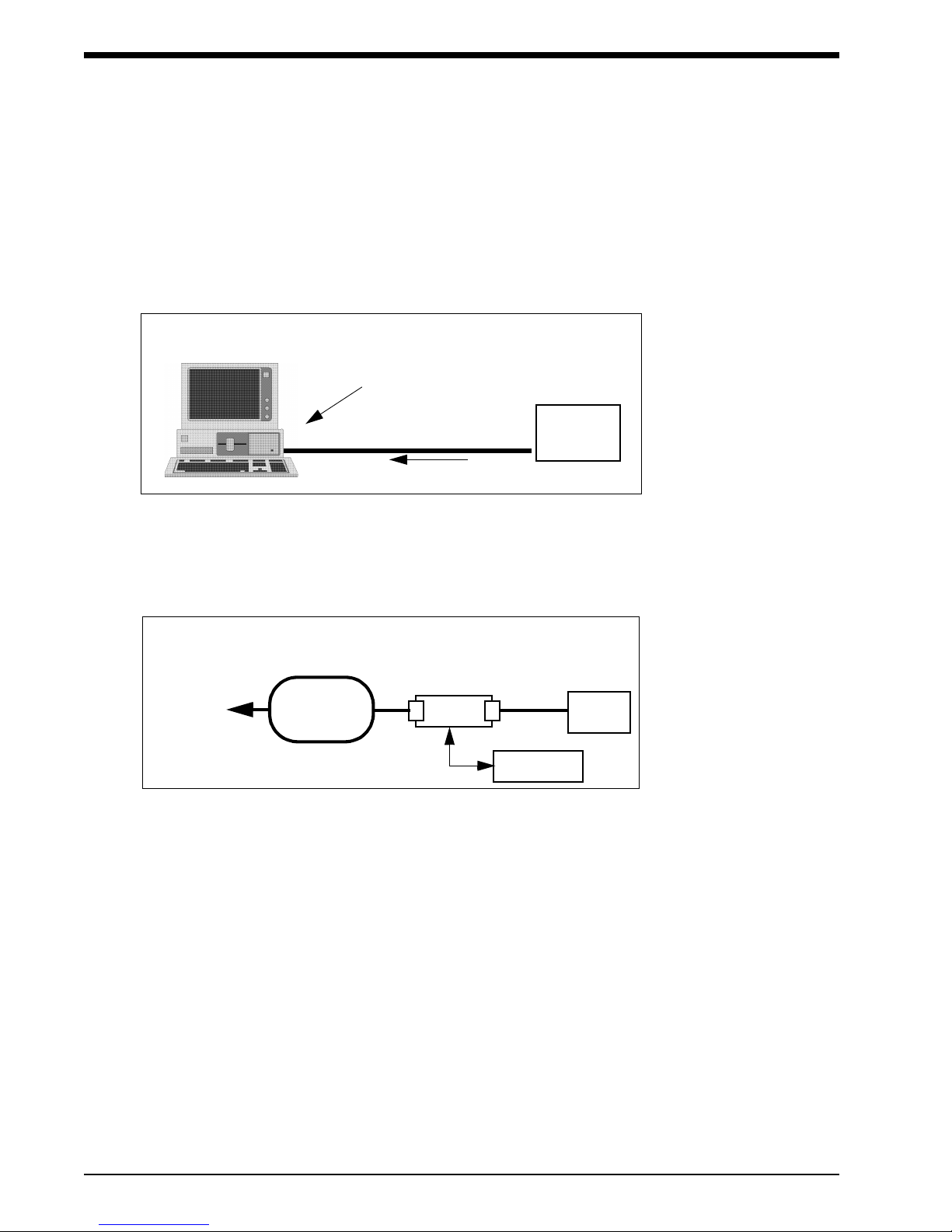
Connecting Directly to a Local Report Generator
For a direct connection to the 90207 or 90217 monitor, place the monitor into the chute on the
Report Generator (Model 90239A or equivalent) as shown below.
!•Once the lithium battery has been completely discharged, it is considered non-
hazardous and can be safely discarded.
LOCAL REPORT CONFIGURATION
90207/90217 ABP Monitors
1-4
Connecting Directly to the PC Interface
For a direct connection to a PC-compatible computer via a Model 90121,
90219-02, or 90219-03:
Connect the ABP interface cable to the serial port on the 90219 or 90121 system and to the
monitor. Refer to the 90121 ABP Report Management System Operations Manual for more
information on the report management system.
Connecting to the Base Station via Modem
For a modem connection to a remote IBM XT/AT/PS2 (or equivalent) base station, refer to the
following figure.
!•The actual initialization procedure is discussed in the 90219 ABP PC
Interface/Base Station Operations Manual (P/N 070-0238-XX).
PC INTERFACE DIRECT CONNECT CONFIGURATION
cable to serial port ABP
Monitor
90219 or 90121 System
ABP
Monitor
MODEM CONNECTION CONFIGURATION
MODEM
PHONE
PUBLIC
TELEPHONE
NETWORK
TO
BASE
STATION
MODEM
cable to
serial port

Operation
1-5
Modem Speed and Compatibility Issues
The 90207 and 90217 operate Hayes-compatible modems only. You can identify your model type by
plugging the communications cable into your 90207/90217 unit and looking at the numbers on the
display. The acceptable modem types and maximum speeds of 90207/90217 units are summarized
below:
Connection Procedure
1. If you are using an older 90207 with a 1200 modem, set the switches on the modem as follows:
2. Connect the serial port cable (P/N 012-0096-00) between the monitor and the modem.
To initialize the monitor for remote connection:
1. Contact the base station by telephone (for remote operation only).
2. Ask the base station operator to initialize the monitor. Give the following information to the
operator:
•Patient's name
•Patient ID number
•Whether monitor display is to be active or not
•Time of day (12- or 24-hour format)
•Whether to display measurement (systolic/diastolic and heart rate)
MODEL TYPE MAX SPEED MODEMS
ACCEPTED DISPLAY
Older 90207 1200 1200 only 9999
Newer 90207 1200 Any Hayes 1999/9999
Older 90217 up to 9600 up to 9600 2999/9999
Newer 90217 9600 Any Hayes 0999/9999
SWITCH #
SETTING AT
MONITOR SITE
1down
2up
3down
4down
5down
6up
7up
8down
9up
10 up
!•If call waiting or call forwarding are options on a telephone used to transfer data,
ensure that both are deactivated or modem communications may be interrupted.
In addition, telephone systems such as CBX or PBX can cause interference with
the modem or the modem can cause interference with the switching system.

90207/90217 ABP Monitors
1-6
•Multiple or single cycle times. If using a single cycle for the 24-hour monitoring period,
indicate the cycle interval and whether the tone is on or off. For multiple cycle time, specify
each cycle interval and whether the tone is on or off for each cycle.
•Any other information the base station operator may request.
3. The base station operator enters the patient information in the computer.
4. Prepare the monitor to receive the patient data from the base station.
•Turn on the modem.
•When instructed by the base station operator, turn the ABP monitor on.
5. When the transfer of information is complete, the ABP monitor will beep. Voice communication
is restored after the monitor beeps.
•Turn off the monitor. Disconnect the monitor from the modem.
•If direct connection between the monitor and the base station is used, turn the monitor off and
disconnect it from the ABP data interface unit.
To transfer readings from the monitor to the base station:
1. Contact the base station by telephone (for remote operation only).
2. Ask the base station operator to read the monitor. Give the following information to the operator:
•Patient's name
•Patient ID number
•Any other information the base station operator may request.
3. The base station operator enters the patient information in the computer. (If the monitor is in a
remote location, the operator turns the base station modem on.)
4. Prepare the monitor to transfer data to the base station.
•Turn on the modem
•When instructed by the base station operator, turn the ABP monitor on (for remote operation
only).
5. When the transfer of information is complete, the ABP monitor will beep. Voice communication
is restored after the monitor beeps.
Turn off the monitor. Disconnect the monitor from the modem.
Modem Indicator Lights
Modem indicators at the local modem are lit, flashing or unlit depending on the stage of operation.
When the monitor is turned on, the RD (Receive Data) and SD (Send Data) lights will flash for
several seconds. The OH (On Hook) indicator becomes lit when the monitor starts communicating
with the remote modem. When the modems connect, the CD (Carrier Detect) is lit. The SD and RD
lights flash as data is being transferred.
!•The modem link must be established within 10 to 20 seconds for the 90207, and
45 seconds for the 90217. If this does not occur, turn the monitor off and then
on again to retry.
!•The modem link must be established within 10 to 15 seconds for the 90207, and
45 seconds for the 90217. If this does not occur, turn the monitor off and return to
step 1.

Operation
1-7
After the transmission is complete and the monitor is turned off, the HS, TR and MR indicators will
always remain lit at the local modem.Setup Test
Turn on the ABP monitor. It will display "9999." When the monitor is being read or initialized, the
digits will change to indicate that communication is taking place between the monitor and the
analysis system. When communication is complete, the digits will stop changing.
Office Check Mode
The monitor automatically enters an office check mode for the first five measurements immediately
following initialization. This allows you to verify the performance of the monitor on an individual
patient without the need for
re-initialization to reset the display features.
While in the office check mode, the monitor will operate as follows:
•Display the cuff pressure on each bleed step
•Display systole, diastole, and heart rate at the end of the measurement
•Bleed one step below the diastolic value as determined by the monitor
Terminating Office Check Mode
For the 90207 (versions earlier than 2.14), press the START/STOP key twice to cancel each of the
remaining readings. The office check mode is terminated when the sum of the canceled and
successful measurements equals five.
For the 90217 and 90207 (version 2.14 and later), press the START/STOP key twice to cancel a
single blood pressure reading. The office check mode is terminated when a blood pressure reading
is cancelled.
Any event that prevents a successful blood pressure measurement (other than a manual cancel) is
not counted as one of the five office check mode readings.
Reinstating Office Check Mode
The office check mode can be reinstated in the 90217, and in versions 2.14 and later of the 90207.
To reinstate the office check mode without initialization of the monitor follow the steps below.
1. Turn the power on to the monitor.
2. When the version is displayed on the LCD press and hold the START/STOP key.
3. Release the START/STOP key when EC03 is displayed on the LCD.
An EC13 will be logged to indicate the time at which the office check mode was reinstated. The
office check mode will be enabled for five additional successful measurements.
!•Verify that cable connections are secure.

90207/90217 ABP Monitors
1-8
Preparing the Patient and Precautions for Use
After the monitor has been initialized, prepare the patient for monitoring as follows:
1. Turn on the monitor (wait for the monitor to perform self-tests). When the LCD displays the
current time, the monitor is ready for operation.
2. Strap the monitor to the patient on the hip opposite the side on which the cuff is worn. Secure the
monitor using the patient’s own belt or the ABP pouch strapped over the opposite shoulder.
When using the shoulder strap, use the belt supplied with the monitor or the patient’s belt to
provide additional security.
!•Blood pressure measurements determined with this device are equivalent to those
obtained by a trained observer using the cuff/stethoscope auscultation method,
within the limits prescribed by the American National Standard, Electronic or
automated sphygmomanometers.
The fifth Korotkoff sound was used to determine overall efficiency.
•As in manual auscultatory methods, accurate readings might not always be
achieved under some conditions. Patient movement, the position of the cuff
relative to the level of the heart, extreme heart rates and blood pressures, various
arrhythmias, and the subject’s physiological condition and other factors can hinder
an accurate reading. Vibration, such as that in a moving automobile, is an
environmental problem that can affect readings.
•When some of the above factors prevent an accurate reading, an event code is
provided to indicate the reason for the missed blood pressure reading. When only
a single blood pressure parameter (systole, diastole, or mean arterial pressure) is
obscured and the other two parameters are measured, the obscured parameter
can be replaced with a computed value.
•If such a value is computed in the 90217, it appears on the report in angle
brackets, e.g. < value >. On the monitor display, dashes are displayed instead of
the estimated value. The ratio used in the formula is determined by the previous
successful measurements of the pressure, rather than a fixed ratio.
•Consult a physician for interpretation of pressure measurements.
C
AUTI
O
N:
•The ABP unit is not for use with defibrillators. Please remove the ABP unit
prior to use with a defibrillator.
•For patients in shock, indirect methods of measuring pressure
(auscultatory, oscillometric, Doppler) may not be reliable due to peripheral
vascular changes. In some cases peripheral pulses or Korotkoff sounds
may be diminished or disappear in spite of adequate blood pressure. Direct
blood pressure measurements (invasive) should be considered in patients
with signs of shock or for any patient who becomes unstable for unknown
reasons.
•The ABP unit might not perform to specifications if stored or used outside
the following ranges:
Operating: temperature between 0oand 40oC, and
relative humidity between 10% and 95%.
Storage: temperature between -30oand 65oC, and
relative humidity between 10% and 95%.

Operation
1-9
3. Proper cuff selection and application is essential in ensuring the accuracy of blood pressure
measurements. To select the proper cuff, first measure the circumference of the limb at the point
where the cuff is to be applied. Match the limb measurement to the range of appropriate
circumferences (in centimeters) specified on each cuff (refer to the table below).
4. Position the cuff so that the center of the inflatable bladder is directly over the brachial artery. The
center of the bladder location is marked on the outside of the cuff. Once the proper position is
determined, the cuff must be tightened to ensure that it is equally snug at the top and bottom
edges and that it is not kinked. This is especially important on larger arms. Insert a finger
between the cuff and the limb to ensure it is not too tight. It may be necessary to wrap the cuff
with its tail at an angle to achieve uniform tightness. If the cuff is not equally snug at the top and
bottom edges, the number of readings available will be limited and the monitor may indicate that
the cuff is improperly applied.
5. Once cuff is applied, the arm should be relaxed at the patient’s side. To avoid reading errors due
to hydrostatic pressure differences, the level of the cuff on the arm should be near the level of
the heart.
CUFF SIZE
LIMB
CIRCUMFERENCE
Pediatric 13 to 20 cm
Small Adult 17 to 26 cm
Average Adult 24 to 32 cm
Large Adult 32 to 42 cm
Extra-large Adult 38 to 50 cm
!•Use only Spacelabs Medical cuffs with this monitor. Using other manufacturer’s
cuffs may result in inaccurate readings even if the manufacturer’s recommended
size is observed.
•If the cuff is too small, pressure readings may be falsely high; a cuff that is too
large produces a falsely low reading. The bladder can be positioned in the cuff for
either the left or right arm.
C
AUTI
O
N:
•Avoid compression or restriction of pressure in the NIBP patient connector
tubes. Check that operation of the equipment does not result in prolonged
impairment of circulation.
•Do not apply cuff to areas of breached or injured skin.
•Cuff hose connections use luer fittings. Be careful not to connect the ABP
monitor into an intravenous fluid line when working close to them.
•This product contains natural latex rubber components to which some
people may be allergic. These components include the bladder and the first
four inches of tubing extending from the cuff.
90207/90217 ABP Monitors
1-10
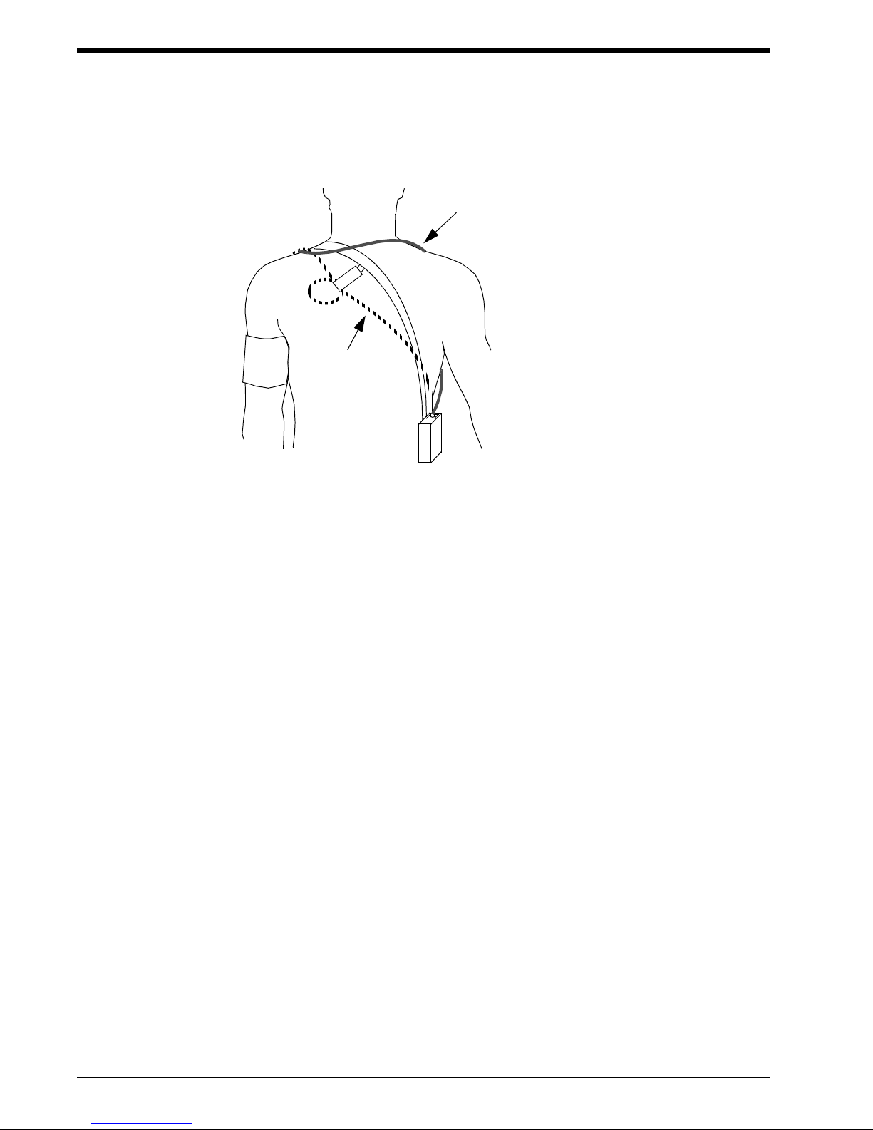
6. Lead the hose up the arm with the cuff and place it across the back of the patient. Drape the hose
so it does not cause the patient discomfort and is not pinched shut by too tight a radius. The
following figure shows the most common positions for the cuff hose.
7. Connect the hose to the monitor.
8. To verify proper monitor operation, take one or more blood pressure readings. Push the
START/STOP key to begin a measurement. Spacelabs Medical recommends taking three
readings in the office so that the patient becomes comfortable with operation of the monitor and
the measurement process.
9. Show the patient how to enter information in the patient diary. Make sure the patient knows what
to do if the cuff becomes very uncomfortable during a measurement, slips out of place, or event
codes are displayed on the monitor screen (refer to Patient Instructions on page -11). In addition,
ensure the patient knows how to care for the monitor.
10. When you are satisfied the monitor is operating properly, the remaining measurements in the
check mode can be canceled. Refer to Office Check Mode on page -7.
Using Cuff Support
1. Once the cuff is successfully applied to the patient, put the large loop of the support around the
opposite arm. Adjust the length so the junction of the straps fits well back on the shoulder towards
the neck.
2. Fasten the rear short strap to the rear of the arm pit. Be careful to clip to the material only and
not to the bladder.
3. Fasten the front strap to the top layer of the cuff material at the location where the hose exits the
cuff. Adjust the length of these straps to apply a minor amount of tension to hold the cuff in
position.
!•Keeping the blood pressure cuff in place is very important both for patient
comfort and for accuracy of the readings. This becomes particularly challenging
when the arm has considerable taper, as is often the case with obese patients.
ALTERNATIVE #1
ALTERNATIVE #2

Operation
1-11
Correlating with Manual Readings
The monitor bleeds pressure in discrete steps (not continuously) using the oscillometric method of
blood pressure determination. If manual pressure readings are taken simultaneously with the
monitor readings, interpolation is required to accurately correlate monitor systolic and diastolic
pressure values with the manual auscultatory pressures.
•For systole, record the first pressure at which a Korotkoff sound is heard. Actual systolic
pressure is somewhere between the pressure when the sound is heard and the previous
(higher) pressure where no sound was heard. The interval of uncertainty can be reduced by half
by adding one half of the bleed step size (4 mmHg) to the manual systolic pressure.
•For diastole, record the cuff pressure at which the last Korotkoff sound was heard. Actual
diastolic pressure is somewhere between that pressure and the next lower pressure. Thus, you
must subtract one half of the bleed step size (4 mmHg) from the manual diastolic pressure.
Patient Instructions
If the cuff becomes uncomfortable during a reading, make certain the patient knows how to
terminate the readings by pressing the STOP key on the front of the monitor.
If the cuff slips out of place, make certain the patient understands correct repositioning of the cuff for
successful readings. If the cuff is not properly positioned, event codes may appear on the monitor.
!•The patient should make every effort to keep the monitor dry. However, there is
no hazard if the monitor does get wet. If this occurs, turn the monitor off and return
it to Spacelabs Medical for service.

90207/90217 ABP Monitors
1-12
Data Transfer and Reports
After monitoring is complete, connect the monitor to either a PC Direct or Base Station interface to
transmit patient data and generate blood pressure reports. Refer to 90121 ABP Report
Management, 90219-02/03 ABP PC Interface/Base Station, or 90239 ABP Report Generator
Operations Manuals for more details.
Cleaning
Visually inspect the monitor, air hose, and pressure cuff for dirt, debris, frayed or worn areas, etc.
prior to patient use.
Cleaning the Monitor
Use a soft, damp cloth and mild detergent mixed with water to wipe the exterior of the monitor. Clean
the air hose with isopropyl alcohol.
Cleaning the Cuff and Carrying Pouch
Small soiled or stained areas may be cleaned by gentle scrubbing with a sponge or cloth soaked in
a mild soap and water solution.
The cuff wrap (with the air bladder removed) and the pouch are machine washable on “delicate”
cycle only. Do not wash in large commercial-type washers or with bed linens or gowns.
Ensure that the carrying pouch is dry before re-use.
Removing/Installing the Bladder
To remove the bladder, follow the steps listed below.
1. Using fingers only, fold or roll up the bladder inside the cuff. Do not use pencils, pens, or other
hard objects as these may damage the bladder.
2. Remove the bladder through the hose exit opening.
Once the bladder has been removed, mate together the hook and loop surfaces of the velcro
attachment before washing.
!•Any pulse rate obtained from the ABP cuff should be used only as a guideline
for the heart rate.
Operation
1-13
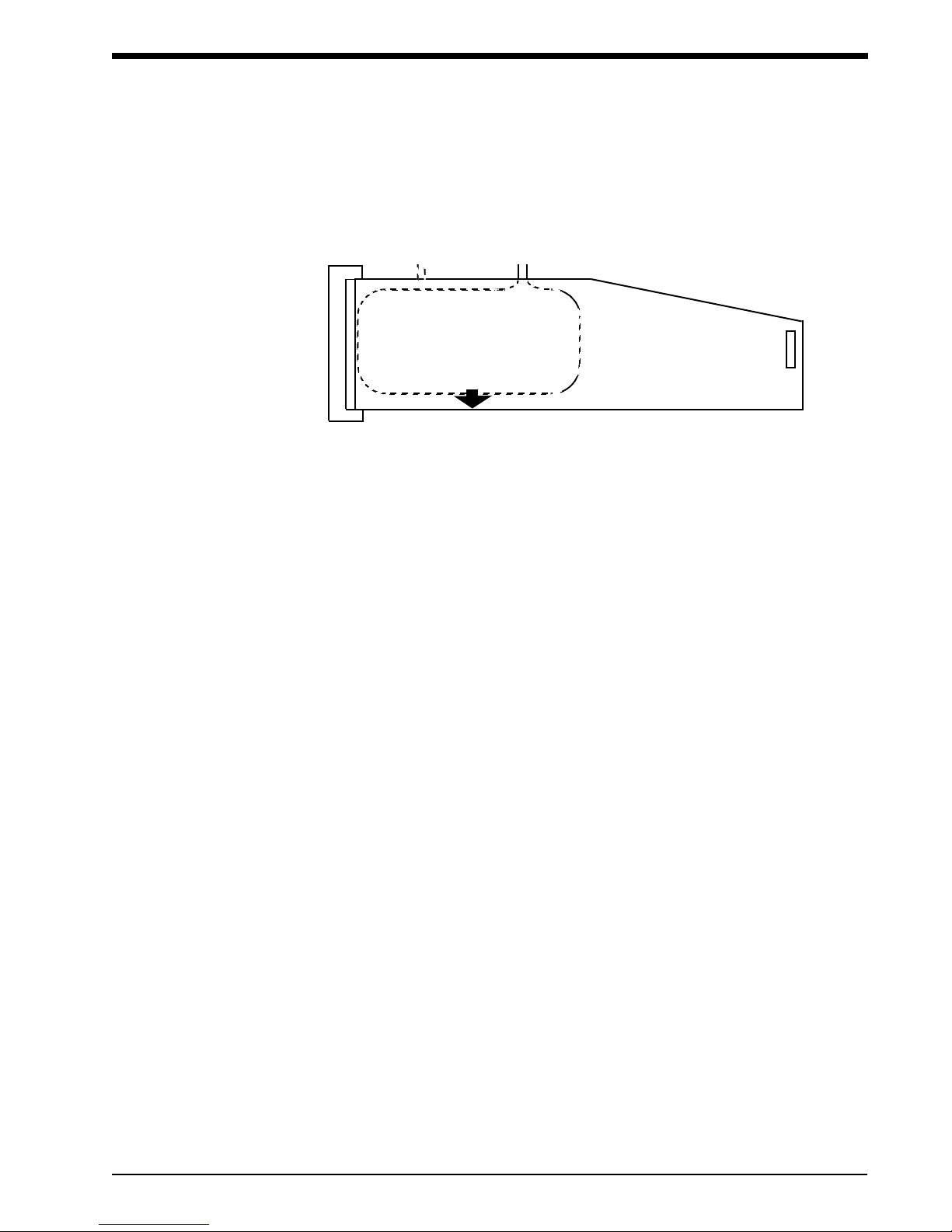
Re-install the bladder into the cuff wrap in reverse order. Make certain that all folds in the bladder
have been removed, and that the long end of the bladder fits into the long end of the cuff (see the
figure below).
!•The cuff hose can exit from either opening in the cuff, depending on whether you
plan a right arm or left arm application.
ARTERY
BLADDER
(shown inserted into cuff wrap
for left arm application)
OPENING FOR
RIGHT ARM
OPENING FOR
LEFT ARM

90207/90217 ABP Monitors
1-14
Event Codes
The monitor will display an event code whenever an event prevents the unit from successfully
completing a blood pressure measurement. The two numerical digits of the event code indicate the
reason the measurement was aborted. The table below lists event codes that are displayed on the
monitor, as well as event codes that appear on the Event Code Report.
Monitor Report Condition
EC00
EC10 Excess movement artifact. Frequent EC10 messages may indicate an air
leak.
EC20 A) A very large number of movement artifacts
B) Heart rate arrhythmia
EC30 A) Movement artifact at mean arterial pressure
B) Heart rate arrhythmia
EC40 A) Movement artifact at asystole
B) Heart rate arrhythmia
EC50 A) Movement artifact at diastole
B) Heart rate arrhythmia
EC60 A) Movement artifact
B) Heart rate arrhythmia
EC70 Systole was found to be above the highest cuff pressure. However, this
result appears to be an error caused by motion artifact. Therefore, the cuff
will not be inflated to a higher pressure on the next measurement attempt.
EC80 A) Movement artifact
B) Heart rate arrhythmia
EC90 A) Movement artifact
B) Heart rate arrhythmia
EC01
EC11 Did not pump above the mean arterial level
EC21 Did not pump above systolic pressure
EC91 Systole appears higher than the selected maximum cuff pressure limit
EC02
EC12 Did not reach initial cuff pressure. The cuff may have been improperly
applied or there may be an air leak.
EC22 Overpressure
EC32 Overpressure
EC42 No cuff attached
EC52 Kinked hose
EC62 Cuff applied too loosely
Other manuals for 90207
1
This manual suits for next models
1
Table of contents
Other Spacelabs Blood Pressure Monitor manuals


Popular Blood Pressure Monitor manuals by other brands

Terraillon
Terraillon TENSIOSMART user manual

Microlife
Microlife Deluxe BPM3 instruction manual

Veridian Healthcare
Veridian Healthcare SmartHeart 01-540 series quick start guide

Medisana
Medisana MTD instruction manual

smartheart
smartheart 01-539 quick start guide

Omron
Omron IntelliSense HEM-790ITCAN instruction manual


