Spacelabs 90217 User manual

more time to care
Ambulatory Blood Pressure
Monitor
90217/90217Q
Service Manual
070-0502-00 Rev. F

© 2004 Spacelabs Medical, Inc.
All rights reserved. Contents of this publication may not be reproduced in any form without the written permission of Spacelabs
Medical. Products of Spacelabs Medical are covered by U.S. and foreign patents and/or pending patents. Printed in U.S.A.
Specifications and price change privileges are reserved.
Spacelabs Medical considers itself responsible for the effects on safety, reliability and performance of the equipment only if:
• assembly operations, re-adjustments, modifications or repairs are carried out by persons authorized by Spacelabs
Medical, and
• the electrical installation of the relevant room complies with the requirements of the standard in force, and
• the equipment is used in accordance with the operations manual.
Spacelabs Medical will make available, on request, such circuit diagrams, component part lists, descriptions, calibration instructions
or other information which will assist appropriately qualified technical personnel to repair those parts of the equipment which are
classified by Spacelabs Medical as field repairable.
Spacelabs Medical is committed to providing comprehensive customer support beginning with your initial inquiry through purchase,
training, and service for the life of your Spacelabs Medical equipment.
CORPORATE OFFICES
U.S.A.
Spacelabs Medical, Inc.
5150 220th Ave SE
Issaquah, WA 98029
Telephone: 425-657-7200
Telephone: 800-522-7025
Fax: 425-657-7212
Authorized EC Representative
UNITED KINGDOM
Spacelabs Limited
71 Great North Road, Hatfield
Herts AL9 5EN
Telephone: 44-1707-263-570
Fax: 44-1707-260-065
BirthNet, Data Shuttle, Flexport, Intesys Clinical Suite, Maternal Obstetrical Monitor, MOM, Mermaid, Multiview, PCIS, PCMS,
PrintMaster, Quicknet, Sensorwatch, TRU-CAP, TRU-CUFF, TRU-LINK, UCW, Ultralite, Ultraview, Ultraview Clinical Messenger,
Ultraview SL, Uni-Pouch, Universal Flexport, Varitrend and WinDNA are trademarks of Spacelabs Medical, Inc.
Other brands and product names are trademarks of their respective owners.
CAUTION:
US Federal law restricts the devices documented herein to sale by, or on the order
of, a physician.
Rx
Only

Contents
i
Table of Contents
Introduction
Overview. . . . . . . . . . . . . . . . . . . . . . . . . . . . . . . . . . . . . . . . . . . . . . . . . . . . . . . . . . . . . . . . . . . . . . . . . . . . . . . . . 1-1
User Controls . . . . . . . . . . . . . . . . . . . . . . . . . . . . . . . . . . . . . . . . . . . . . . . . . . . . . . . . . . . . . . . . . . . . . . . . . . . . . 1-2
Display . . . . . . . . . . . . . . . . . . . . . . . . . . . . . . . . . . . . . . . . . . . . . . . . . . . . . . . . . . . . . . . . . . . . . . . . . . . . . . . . . . 1-2
Programming Options. . . . . . . . . . . . . . . . . . . . . . . . . . . . . . . . . . . . . . . . . . . . . . . . . . . . . . . . . . . . . . . . . . . . . . . 1-3
Setup
Installing the Batteries . . . . . . . . . . . . . . . . . . . . . . . . . . . . . . . . . . . . . . . . . . . . . . . . . . . . . . . . . . . . . . . . . . . . . . 2-1
Initializing the Monitor. . . . . . . . . . . . . . . . . . . . . . . . . . . . . . . . . . . . . . . . . . . . . . . . . . . . . . . . . . . . . . . . . . . . . . . 2-2
Operational Tests . . . . . . . . . . . . . . . . . . . . . . . . . . . . . . . . . . . . . . . . . . . . . . . . . . . . . . . . . . . . . . . . . . . . . . . . . . 2-7
Theory
Pressure Amplifier . . . . . . . . . . . . . . . . . . . . . . . . . . . . . . . . . . . . . . . . . . . . . . . . . . . . . . . . . . . . . . . . . . . . . . . . . 3-1
Oscillometric Amplifier . . . . . . . . . . . . . . . . . . . . . . . . . . . . . . . . . . . . . . . . . . . . . . . . . . . . . . . . . . . . . . . . . . . . . . 3-2
90217 Block Diagram . . . . . . . . . . . . . . . . . . . . . . . . . . . . . . . . . . . . . . . . . . . . . . . . . . . . . . . . . . . . . . . . . . . . . . . 3-4
Digital Circuitry . . . . . . . . . . . . . . . . . . . . . . . . . . . . . . . . . . . . . . . . . . . . . . . . . . . . . . . . . . . . . . . . . . . . . . . . . . . . 3-5
Unit Power . . . . . . . . . . . . . . . . . . . . . . . . . . . . . . . . . . . . . . . . . . . . . . . . . . . . . . . . . . . . . . . . . . . . . . . . . . . . . . . 3-6
Software Flow Chart . . . . . . . . . . . . . . . . . . . . . . . . . . . . . . . . . . . . . . . . . . . . . . . . . . . . . . . . . . . . . . . . . . . . . . . . 3-8
Maintenance
Cleaning . . . . . . . . . . . . . . . . . . . . . . . . . . . . . . . . . . . . . . . . . . . . . . . . . . . . . . . . . . . . . . . . . . . . . . . . . . . . . . . . . 4-1
Calibration Check . . . . . . . . . . . . . . . . . . . . . . . . . . . . . . . . . . . . . . . . . . . . . . . . . . . . . . . . . . . . . . . . . . . . . . . . . . 4-3
Calibration Procedures . . . . . . . . . . . . . . . . . . . . . . . . . . . . . . . . . . . . . . . . . . . . . . . . . . . . . . . . . . . . . . . . . . . . . . 4-4
Operational Verification . . . . . . . . . . . . . . . . . . . . . . . . . . . . . . . . . . . . . . . . . . . . . . . . . . . . . . . . . . . . . . . . . . . . 4-10
Manifold Kit - P/N 050-0110-xx. . . . . . . . . . . . . . . . . . . . . . . . . . . . . . . . . . . . . . . . . . . . . . . . . . . . . . . . . . . . . . . 4-14
Disassembly Procedures . . . . . . . . . . . . . . . . . . . . . . . . . . . . . . . . . . . . . . . . . . . . . . . . . . . . . . . . . . . . . . . . . . . 4-15
Troubleshooting
Monitor Event Codes . . . . . . . . . . . . . . . . . . . . . . . . . . . . . . . . . . . . . . . . . . . . . . . . . . . . . . . . . . . . . . . . . . . . . . . 5-1
Base Station Report Event Codes . . . . . . . . . . . . . . . . . . . . . . . . . . . . . . . . . . . . . . . . . . . . . . . . . . . . . . . . . . . . . 5-3
Problem Solving Checklist . . . . . . . . . . . . . . . . . . . . . . . . . . . . . . . . . . . . . . . . . . . . . . . . . . . . . . . . . . . . . . . . . . . 5-5
Parts
90217 Field Replaceable Parts Lists . . . . . . . . . . . . . . . . . . . . . . . . . . . . . . . . . . . . . . . . . . . . . . . . . . . . . . . . . . . 6-1
Drawings. . . . . . . . . . . . . . . . . . . . . . . . . . . . . . . . . . . . . . . . . . . . . . . . . . . . . . . . . . . . . . . . . . . . . . . . . . . . . . . . . 6-3
Symbols
Appendix A — Electromagnetic Compatibility
Electromagnetic Emissions. . . . . . . . . . . . . . . . . . . . . . . . . . . . . . . . . . . . . . . . . . . . . . . . . . . . . . . . . . . . . . . . . . .A-1
Electromagnetic Immunity . . . . . . . . . . . . . . . . . . . . . . . . . . . . . . . . . . . . . . . . . . . . . . . . . . . . . . . . . . . . . . . . . . . A-1
Frequency Separation Distances . . . . . . . . . . . . . . . . . . . . . . . . . . . . . . . . . . . . . . . . . . . . . . . . . . . . . . . . . . . . . .A-2


Contents
1-1
Introduction
Overview . . . . . . . . . . . . . . . . . . . . . . . . . . . . . . . . . . . . . . . . . . . . . . . . . . . . . . . . . . . 1
User Controls. . . . . . . . . . . . . . . . . . . . . . . . . . . . . . . . . . . . . . . . . . . . . . . . . . . . . . . . 2
Display. . . . . . . . . . . . . . . . . . . . . . . . . . . . . . . . . . . . . . . . . . . . . . . . . . . . . . . . . . . . . 2
Programming Options . . . . . . . . . . . . . . . . . . . . . . . . . . . . . . . . . . . . . . . . . . . . . . . . . 3
Overview
The Model 90217 is a small, lightweight battery-powered Ambulatory Blood Pressure (ABP)
monitor that uses the noninvasive Oscillometric method to measure blood pressure and heart rate.
This data is then stored into memory for later transfer to an ABP Analysis System
(FT1000A/FT2000A or equivalent), a PC Interface, a Base Station, or a Report Generator for data
analysis, report printing, and archiving.
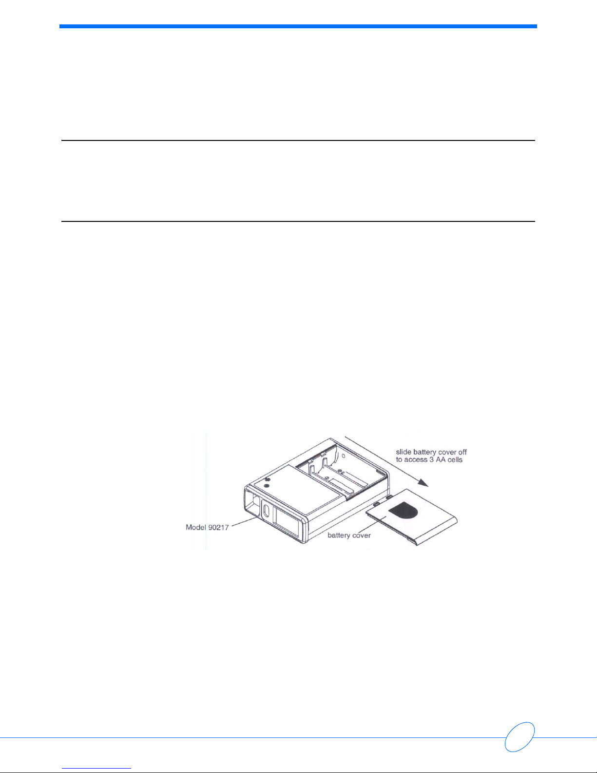
The 90217 monitor is housed in a plastic case with a removable battery cover that provides access
to its three AA cells. Inside the monitor are three printed circuit boards: the Main, Power, and
Display boards.
Programming resides in an internal 128 KB RAM and microprocessor ROM. Most of the code
exists in the RAM and can be updated via an infrared (IR) serial port located at the rear of the unit.
The internal ROM contains a boot code and other codes for downloading and completing special
tasks.
The IR serial port transfers collected data to a report generator and sends setup changes to the
ABP monitor.
A rechargeable lithium battery keeps the RAM and real-time clock backed up during periods when
the AA batteries are removed.
Note:
Beginning with August 2004 shipments, all 90217 models have a “Q” suffix, indicating a quick-
disconnect fitting for cuffs. Prior versions had a Luer fitting. This manual includes information
relating to both.

Ambulatory Blood Pressure Monitor 90217 Service Manual
1-2
User Controls
The 90217 ABP monitor provides two user controls: a START/STOP button and a Power ON/OFF
switch.
Power ON/OFF Switch
When turned ON, this switch activates the monitor and begins executing the timed blood pressure
program.
START/STOP Button
This front panel control manually starts a blood pressure measurement, stops a measurement
already in progress, or sets special modes of operation (refer to the 90207, 90217 Ambulatory
Blood Pressure Monitors Operations Manual, P/N 070-0137-xx).
Display
The monitor display is a 4-digit LCD that presents the following information (refer to the 90217
Ambulatory Blood Pressure Monitors, Operations Manual (P/N 070-0137-xx) for instructions on
use).
Systolic/Diastolic Pressure and Heart Rate
Patient information appears on the display sequentially with systolic first, diastolic next, and then
heart rate. Each parameter appears for approximately one second. The screen is blanked for one
second and the sequence of readings is re-displayed two more times.
A bar indicator at the left of the display identifies which parameter is currently being displayed. It
appears next to the “sys” for systolic, next to “dia” for diastolic pressure, and next to the heart
symbol for heart rate.

Ambulatory Blood Pressure Monitor 90217 Service Manual
1-3
Introduction
Time of Day
A real-time clock provides the time of day, which appears between measurement cycles and can
be programmed in either a 12- or 24-hour mode.
Cuff Pressure
This pressure can be shown while the monitor is taking a measurement. If cuff pressure is not
selected, “----” appears. Cuff pressure can be enabled or disabled in software.
Event Code
Event codes are 4-digit LCD messages that begin with “EC” or, in some cases, show specific
codes such as “LLL” for a low battery. If enabled, a beep sounds during an event code and the
code is displayed on the monitor. Refer Troubleshooting on page 5-1 for event code information.
Count Down Sequence
Whenever the monitor begins a measurement cycle, it turns its tone ON (if beep is enabled) and
counts down from 5555 to 1111 on the display.
IR Communications
During IR communications, the monitor first displays 9999 on the LCD to indicate that it has
detected a cable connect and has gone into the communication mode. The monitor periodically
attempts to contact a modem. The left two digits on the monitor display indicate the steps in the
communication process. For more information, refer to Base Station via Modem on page 2-3.
Programming Options
These monitor options are user programmed:
Day or Night Modes
Day mode = beeper ON, inflation time approximately 15 seconds
Night mode = beeper OFF, inflation time approximately 20 seconds
Measurement Intervals and Periods
Measurement intervals are selectable from 6 to 120 minutes (in one minute increments) for each
period. It is also possible to not have readings taken during a specified period. Up to 12 periods
may be defined.
Clinical Verification Mode
When set to this mode, the monitor is forced to bleed to 40 mmHg or to one step below diastole
(whichever is lower) for each reading.

Ambulatory Blood Pressure Monitor 90217 Service Manual
1-4
Office Check Mode
This mode verifies monitor operation and allows a user to view cuff pressure and blood pressure
results regardless of any previous disabling of the display. During Office Check Mode, the monitor
bleeds an additional pressure step below diastole.
This mode is enabled for the first five successful blood pressure readings (or attempted readings)
following monitor initialization. Office Check can be disabled by a patient cancel and can be re-
enabled after turning the power switch ON and holding the START/STOP button in while the last
digit of the software version number is displayed.
Blood Pressure/Heart Rate Measurements Displayed
These measurements can be selected to appear or not to appear at the end of a measurement.
Cuff Pressure Displayed
This measurement can be selected to appear or not to appear during the measurement cycle.
Contents
2-1
Setup
Installing the Batteries . . . . . . . . . . . . . . . . . . . . . . . . . . . . . . . . . . . . . . . . . . . . . . . . . 1
Initializing the Monitor . . . . . . . . . . . . . . . . . . . . . . . . . . . . . . . . . . . . . . . . . . . . . . . . . 2
Operational Tests . . . . . . . . . . . . . . . . . . . . . . . . . . . . . . . . . . . . . . . . . . . . . . . . . . . . 7
Installing the Batteries
Two types of batteries are used in the 90217 ABP Monitor: three standard AA batteries (Spacelabs
Medical P/N 146-5011-xx) to power the cuff air pump, and one rechargeable lithium battery to
backup the clock and RAM circuits when the AA batteries are removed or are exhausted. This
lithium battery receives its charge from the AA batteries and does not normally require
replacement. Its expected life is at least nine years.
If alkaline batteries are used as the AA batteries, they must be replaced after each patient use.
Nickel cadmium batteries require a full charge before each use.
AA Batteries
To replace the three AA batteries:
1Switch the monitor’s power switch to OFF.
2Remove the battery compartment cover plate by sliding it to the right until it can be pulled free.
3If present, remove the old AA batteries from the monitor and replace each with a fresh alkaline
battery (or fully charged nickel cadmium), being careful to match polarities where indicated (+
or -).
Note:
The monitor will not operate if batteries are incorrectly installed.
If the monitor is going to be stored longer than two weeks, remove the AA batteries to
prevent the possibility of leakage or discharge. Spacelabs Medical is not responsible
for product damage caused by battery leakage. If your unit has been damaged by a
leaky battery, contact the battery manufacturer for any recoverable repair costs.
Ambulatory Blood Pressure Monitor 90217 Service Manual
2-2
4After correctly inserting the batteries, gently slide the battery cover back into place.
5Switch the monitor ON and verify that the display appears. If there is no display, switch the
monitor OFF and refer to in this manual. When power is first switched ON, the first four digits
of the RAM code revision are displayed for about 1 second, followed by a blanked display,
followed by the last two digits of the revision number.
Initializing the Monitor
The ABP monitor must be initialized prior to use. Initialization specifies the monitoring period,
patient information, time format, measurement interval, monitor tone ON/OFF during selected
periods, event code display, and whether or not to display pressure values. To initialize the
monitor, connect it to one of the following analysis systems.
If using 90121 or 92506 products, refer to the appropriate Operations manual for setup and
operation.
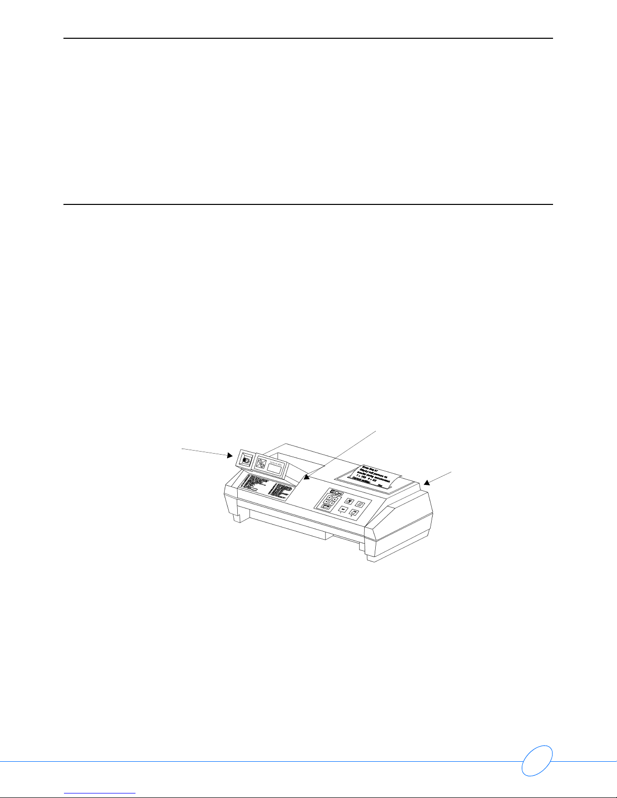
Local Report Generator
For a direct connection to a Local Report Generator, place the monitor into the chute on the Report
Generator (Model 90239A or equivalent):
PC Interface
For a direct connection to an IBM XT/AT/PS2 (or equivalent) via a Model 90219-02/90219-03
(or equivalent):
1Connect the ABP monitor to the 90219 Analysis System.
Local Report Generator Direct Connect Configuration
Ensure that the monitor lines up
against the side to align IR ports
Local Report
Generator
(90239A)
Model
90217
Ambulatory Blood Pressure Monitor 90217 Service Manual
2-3
Setup
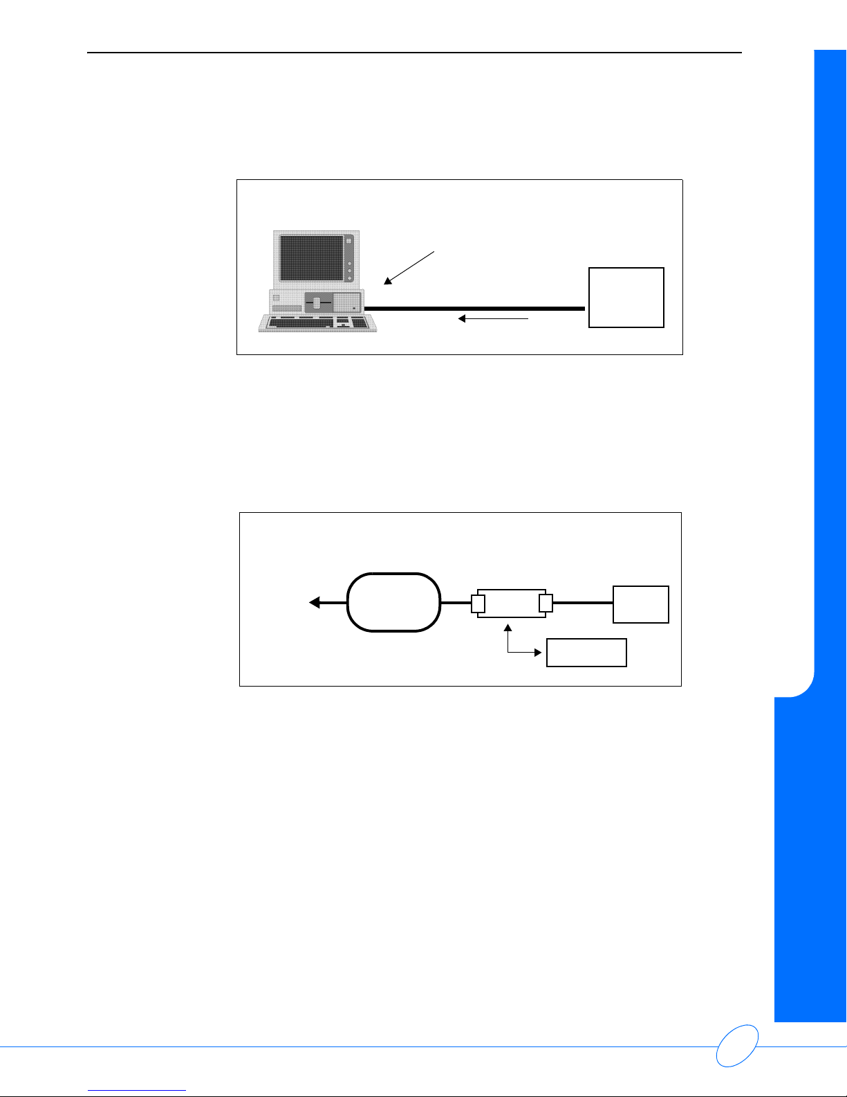
2Connect the 90219 Analysis System cable from the monitor to the serial port on the PC.
3Refer to the 90219 Ambulatory Blood Pressure PC Interface/Base Station Operations Manual
(P/N 070-0238-xx) for instructions for operating the Analysis System.
Base Station via Modem
For a modem connection to a remote IBM XT/AT/PS2 (or equivalent) base station:
Note:
The initialization procedure is provided in the 90219 Ambulatory Blood Pressure PC
Direct/Base Station Operations Manual (P/N 070-0238-xx).
1The 90217 can use one of the following modems for communication:
• Hayes Smartmodem 1200
• Hayes Optima 9600 or equivalent
• Most 2400 baud modems
If the remote site also has 90202 or 90207 monitors, a Hayes Smartmodem 1200 must be used
with those monitors.
High speed modems are set up via software commands.
cable to serial port
90217
Model 90219 Analysis System
PC Interface Direct Connect Configuration
ABP
Monitor
ABP
Monitor
MODEM
PHONE
PUBLIC
TELEPHONE
NETWORK
TO
BASE
STATION
MODEM
cable to
serial port
Modem Connection Configuration

Ambulatory Blood Pressure Monitor 90217 Service Manual
2-4
The Hayes Smartmodem 1200, which attaches to the monitor, must be set up as follows:
2Connect the serial port cable (P/N 012-0096-xx) between the monitor and the modem.
Note:
If call waiting or call forwarding are options on the telephone used to transfer data,
ensure that both are deactivated or modem communications may be interrupted. In
addition, telephone systems, such as CBX or PBX, can cause interference with the
modem, or the modem can cause interference with the switching system.
To initialize the monitor for a remote connection:
1Contact the base station by telephone (for remote operation only).
2Ask the base station operator to initialize the monitor. Give the following information to the
operator:
• Patient's name.
• Patient ID number.
• If the monitor display is to be active or inactive.
• Time of day (12- or 24-hour format).
• If measurements are to be displayed (systolic/diastolic and heart rate).
• Multiple or single cycle times. If using a single cycle for the 24-hour monitoring period,
indicate the cycle interval and whether the tone is ON or OFF. For multiple cycle time,
specify each cycle interval and whether the tone is ON or OFF for each cycle.
• Any other information the base station operator may request.
3The base station operator enters the patient information in the computer.
4Prepare the monitor to receive the patient data from the base station.
• Switch the modem ON.
• When instructed by the base station operator, switch the ABP monitor ON.
Switch # Setting at
Monitor Site
1 down
2up
3 down
4 down
5 down
6up
7up
8 down
9up
10 up

Ambulatory Blood Pressure Monitor 90217 Service Manual
2-5
Setup
Note:
The modem link must be established within 45 seconds for the 90217. If this does not
happen, switch the monitor OFF and return to step 1.
5When the information transfer is complete, the ABP monitor beeps and voice communication is
restored.
• Switch the monitor OFF and disconnect it from the modem.
• If there is a direct connection between the monitor and the base station, switch the monitor
OFF and disconnect it from the ABP data interface unit.
To transfer readings from the monitor to the base station:
1Contact the base station by telephone (for remote operation only).
2Ask the base station operator to read the monitor. Give the following information to the operator:
• Patient's name.
• Patient ID number.
• Any other information that the base station operator may request.
3The base station operator enters the patient information into the computer. (If the monitor is in
a remote location, the operator must turn power to the base station modem ON.)
4Prepare the monitor to transfer data to the base station.
• Switch the modem ON.
• When instructed by the base station operator, switch the ABP monitor ON (for remote
operation only).
Note:
The modem link must be established within 45 seconds for the 90217. If this does not
happen, switch the monitor OFF and return to step 1.
5When the information transfer is complete, the ABP monitor beeps and voice communication is
restored.
• Switch the monitor OFF and disconnect it from the modem.
Modem Indicator Lights
When the monitor is switched ON, the modem’s RD (receive data) and SD (send data) lights flash
for several seconds. The OH (on hook) indicator is lit when the monitor starts communicating with
the remote modem. When both modems connect, the CD (carrier detect) is lit. The SD and RD
lights flash as data is being transferred.
After the transmission is complete and the monitor is turned OFF, the HS, TR and MR indicators
will always remain lit at the local modem.

Ambulatory Blood Pressure Monitor 90217 Service Manual
2-6
90217 Modem Connection Status Indications
The left-most digit of the 90217 display shows the various stages of the modem connection
process:
1 Sending modem identify query.
2 Waiting for response to identify query.
3 Sending modem reset commands.
4 Sending modem setup commands.
5 Send off-hook command.
6 Waiting for contact.
7 Contact established.
9 Not attempting to contact modem.
Once contact has been established, the second digit from the left on the 90217 display indicates
the baud rate of the connection. On high speed modems, the indicated speed refers to the
connection between the ABP monitor and the modem. The two modems may be communicating at
some speed other than that at which the modem is communicating with the monitor.
The baud rate codes are as follows:
0 1200
1 not used
2 2400
3 4800
4 9600
5 19.2 k
6 38.4 k
Setup Test
Note:
Verify that all cable connections are installed correctly and are connected securely.
Switch the ABP monitor ON. It initially displays 9999. When the monitor is being read or initialized,
these digits change to indicate that communication is taking place between the monitor and the
analysis system. When communication is complete, the digits stop changing.
The right-most digit indicates that a message has been sent from the monitor to the base station.
The second digit from the right indicates that a non-garbled message has been received by the
monitor. A common failure mode is with only the right digit spinning. This indicates garbled
messages are being received and an “I don’t understand” response is being transmitted by the
monitor.

Ambulatory Blood Pressure Monitor 90217 Service Manual
2-7
Setup
Operational Tests
Conduct the following procedures to verify proper operation of the 90217 ABP Monitor.
Equipment Required
• 90219-02 system
• 90219-03 ABP Base Station software
• Type AA alkaline batteries (3)
• Cable, 90217 to PC, P/N 012-0097-xx (greater than -02)
• Setup for air leaks (refer to Air Leak Test on page 2-8)
• Analog manometer (optional)
• Stop watch or equivalent
• Battery spring insertion tool, P/N 003-0084-00
Visual Inspection
1Check the display window and ensure that it is clear (free from scratches, contamination, etc.)
with the words SYS DIA appearing on the left side.
2Verify that the front panel START/STOP button responds with a clear “snap” when pressed.
3Inspect inside the battery compartment to ensure that the battery springs are clean and provide
a good electrical contact with the batteries.
4Install the three AA batteries and verify that the battery door closes and latches properly.
Ambulatory Blood Pressure Monitor 90217 Service Manual
2-8
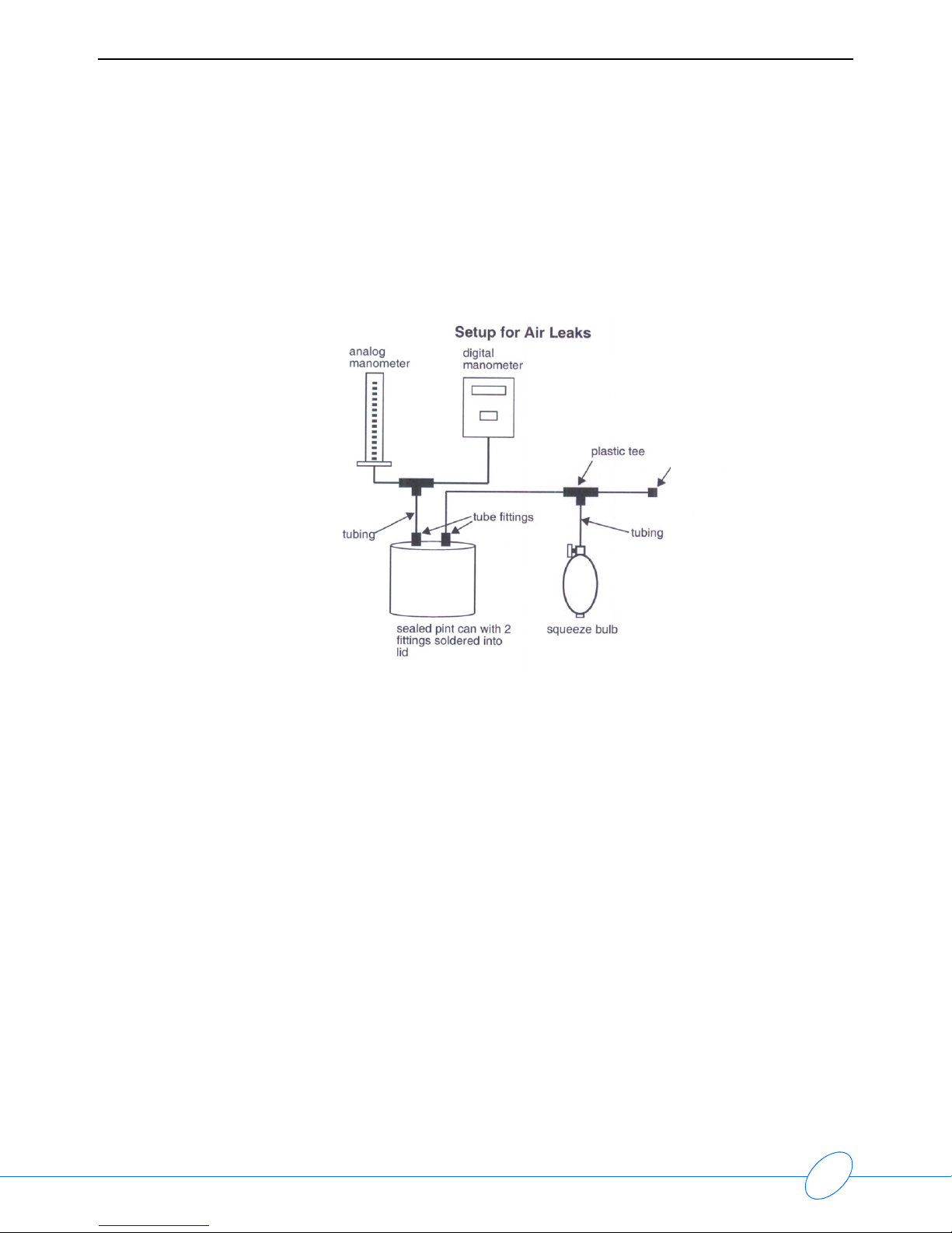
Air Leak Test
1Connect the test setup illustrated below.
Note:
This figure shows the use of both an analog and digital manometer. Both or either can
be used in these tests. If only one manometer is used, block off the unused hose.
2Close the squeeze bulb valve.
3Turn ON the 90217 and press the START/STOP button.
4Verify the following monitor response:
• Two beeps are sounded.
• The display counts down: 5555, 4444, 3333, 2222, 1111.
• Pumping begins and “_ _ _ _” is displayed (could display the pump pressure, depending
upon how the monitor was initialized).
5Verify that the system pumps up to 165 mmHg, ±8 mmHg, before the pressure begins to drop
in 7 to 9 mmHg steps. Ensure that the pressure does not drift down.
Note:
It may take 3 or 4 steps before the cuff size is learned by the monitor and the steps fall
within this range.
6Verify that the display reads EC18.
7Open the bulb valve and remove the monitor from the manometer setup.
fitting

Ambulatory Blood Pressure Monitor 90217 Service Manual
2-9
Setup
PC Interface Test
Note:
The PC Inferface Test is only applicable for use with a PC System that operates with
the 90219 software.
1Connect the system as illustrated:
2Power ON all devices.
3Start the 90219-03 Base Station software (loaded on hard drive).
4Type: ABP (or ABPPCI) and press the Enter key on the base station.
Note:
If the file name has been changed from ABP, type DIR and press Return to determine
the new name.
5Switch the 90217 power switch ON.
6Press (in this order):
Space Bar
1 (ABP communication)
3 (direct connect - skip this step if a PC Interface data key is attached instead of a
base station data key)
2 (read ABP unit)
7Press any key (wait).
8Type 8, press the Enter key, and type Y (yes).
Note:
“8” is the name of a dummy file, which should be setup on the computer already.
9Press the END key.
10 Verify that the clinical data appears on the computer screen. The last reading on this screen is
the results of the test done earlier in these procedures.
11 Verify that the date and time are correct and that the event code EC18 appears.
12 Press the ESC key.
13 Initialize the 90217 by typing:
1 (initialize ABP)
14 Press the END key and use the up arrow key until PATIENT NAME is selected.
15 Type:
TEST and press the Enter key
1234567890 and press the Enter key
NONE and press the END key
16 Verify that the display reads “***MONITOR INITIALIZED***”.

Ambulatory Blood Pressure Monitor 90217 Service Manual
2-10
17 Press:
Space Bar
ESC key
ESC key
ESC key
Y key (yes)
18 Remove the 90217 from the system and switch power OFF.
19 Remove one AA battery.
20 Wait one minute and reinstall the battery.
21 Switch ON 90217 power and verify that the time remained correct.

Contents
3-1
Theory
Pressure Amplifier . . . . . . . . . . . . . . . . . . . . . . . . . . . . . . . . . . . . . . . . . . . . . . . . . . . . 1
Oscillometric Amplifier . . . . . . . . . . . . . . . . . . . . . . . . . . . . . . . . . . . . . . . . . . . . . . . . . 2
90217 Block Diagram . . . . . . . . . . . . . . . . . . . . . . . . . . . . . . . . . . . . . . . . . . . . . . . . . 4
Digital Circuitry . . . . . . . . . . . . . . . . . . . . . . . . . . . . . . . . . . . . . . . . . . . . . . . . . . . . . . 5
Unit Power . . . . . . . . . . . . . . . . . . . . . . . . . . . . . . . . . . . . . . . . . . . . . . . . . . . . . . . . . . 6
Software Flow Chart . . . . . . . . . . . . . . . . . . . . . . . . . . . . . . . . . . . . . . . . . . . . . . . . . . 8
Pressure Amplifier
The pressure amplifier monitors the voltage produced across the pressure transducer. This
voltage is proportional to the pressure in the arm cuff.
The pressure transducer circuits require temperature compensation to account for changes in
sensitivity. This is accomplished by using a reference current to provide a constant current source
into the bridge. Any change in bridge resistance due to temperature will change the bridge voltage
in an amount that compensates for any change in sensitivity.
Voltage across the transducer is amplified differentially and turned into a single ended voltage that
is amplified, offset and sent to the processor’s A/D converter, the oscillometric amplifier and the
overpressure detector.
Offset Adjust
Both transducer offset and operational amplifier offset are nulled out using a pressure offset
adjustment. Minor variations in the offset are tracked and compensated for in software.
Gain Adjust
Changes in gain are compensated for with a gain adjustment. The voltage gain to the A/D
converter is +15 mV/mmHg, and the voltage is offset by approximately 0.09 volts. This 0.09 volts is
inserted to prevent the A/D converter signal from going negative during drifts in the offsets. The
0.09 volt offset is subtracted in software.

Ambulatory Blood Pressure Monitor 90217 Service Manual
3-2
Oscillometric Amplifier
Gain, Offset, and Filtering
The oscillometric amplifier is DC coupled. A D/A converter provides large amounts of DC offset to
the amplifier to prevent the large static pressure component of the waveform from over driving the
amplifier. It provides gain (x64), DC offset, and high frequency filtering (3dB point = approximately
80 Hz). The oscillometric filtering that was present in earlier designs is now done by software.
RAM Protect and Reset Circuit
When the +5 volt power supply begins to drop, the RAM protect circuit asserts a reset signal to the
processor that protects RAM data during power collapse. This same circuit provides a start up
processor reset signal at power up. Reset time is a product of the reset R-C time constant and the
hold off time necessary for the power converter to reach +5 volts (the reset time constant is 350
msec).
A/D Voltage References
The A/D reference (+ADR) is generated from a LM4041-1.2 band gap reference. Its reference
output of 1.2 volts is amplified to 4.608 volts by a gain adjustable amplifier (+ADR = +4.608 volts,
adjustable).
30 Second Pulse
The real-time clock produces a pulse every minute with a 30 second duration. This pulse’s leading
and trailing edges are conditioned into separate pulses and applied through a diode to the
processor’s WAKE_UP line to awaken it every 30 seconds.
Second Pulse
The SECONDS line goes to the LCD where it blinks the colon and changes the LCD polarity.
Cable Connected
If a cable is connected to the RS-232 communications connector with the power switch ON, the
power converter activates and awakens the processor. A cable connected condition prevents the
power converter from going down as a result of a shutdown fault generated by the watch dog
timer, but cannot prevent an over-pressure shutdown. Once a cable has been connected, the
processor goes into a listening mode, awaiting instructions from the RS-232 port.
These instructions adhere to the ABP communications protocol.
This manual suits for next models
1
Table of contents
Other Spacelabs Blood Pressure Monitor manuals


