SpaceLift 5200 Series User manual

Model 5200 Series Attic Lifts
Installation and Operation Manual
Page 1 SpaceLift 5200 Series Attic Lift Manual (10/14)
Protected by U S Patent No 8,292,031
Model Number:
Serial Number:
Installation Date:
Installer:
Place of Purchase:
Date of Purchase:
Congratulations on the purchase of your new SpaceLift
Products 5200 Series attic lift system. Expect to receive
many years of reliable service moving household items
between the floors of your home.
BEST-IN-CLASS FEATURES INCLUDE:
■Low-profile design no vertical restriction
■Automated lift with 200-pound load limit
■Platforms have up to 24 cubic feet capacity
■Factory assembled for ease of installation
■Wall-mounted control unit with key lock
■Load management system
■Two-year factory warranty
5200 SERIES SPECIFICATIONS
■Lift Weight Capacity: 200 lbs
■Lift Speed: 3 inches per second
■Max Vertical Travel: to 15 feet
■Joist/Ceiling Depth: 7 to 14 inches
■Platform Leveling: Variable adjustment
■Power Requirement: 110 VAC – 120 VAC
■Tethers: Stainless steel cable
■Remote Control: Momentary up/down buttons
Model 5222 Model 5228
Dimensions (inches}: 22 W x 59.5 L x 7 H 28 W x 59.5 L x 7 H
Rough Framed Opening: 22.5 x 60 (+/- 1/8) 28.5 x 60 (+/- 1/8)
Internal Platform Area: 18 x 41 24 x 41
Ceiling Drywall Cutout: 22.5 x 46 28.5 x 46
Landing Space Area: 24.5 x 48 30.5 x 48
Unit Weight: 75 lbs 88 lbs
SpaceLift 5200 Series, view stowed in attic floor
SpaceLift 5200 Series, operational perspective

Page 2 SpaceLift 5200 Series Attic Lift Manual (10/14)
IMPORTANT NOTE: Please read this manual completely before you install
and operate the lift. Installation of the SpaceLift 5200 Series attic lift
system should ONLY be performed by a qualified professional. Installation
of the 5200 Series lift systems require skills in carpentry and electrical
wiring. If you c oose to ave t e lift system installed wit out t e use
of a certified installer, you may void portions of t e warranty.
BEFORE YOU BEGIN
1. Open the shipping container and verify contents are
free of any damage that may have occurred during
transport. Check the Contents List to be sure everything
is included.
2. Contact your dealer if the lift system appears damaged.
3. Record the Model Number and Serial Number of the
lift system on the front page of this manual.
IMPORTANT NOTE: Secure ALL packing
and shipping material until installation is
complete and the unit is operating as
intended. These materials are required
should the unit be returned. If you discard
and unit must be shipped there will be
delays and additional charges.
INSTALLATION INSTRUCTIONS
SECTION 1: LOCATION SELECTION
Select a location for installation. Your home must
have an acceptable ceiling and joist structure.
Consult a structural engineer before making any
modifications to the ceiling and joist structure and
to determine the load bearing capacity of the
selected installation area.
LOCATION AND ORIENTATION REQUIREMENTS
•Orientation: Lift must be oriented such
that its length is parallel to the floor joists.
•Finished Floor: Top floor must be
finished with 1/2-inch to 3/4-inch plywood
or comparable material.
•Electrical Outlet: An electrical outlet must be
located within 4 feet of mounted lift system.
•Load Support: Floor must support loads as
specified in local residential building codes.
•Power Requirement: A dedicated 15 amp
circuit is required.
•Landing Area: Landing area for cargo tray with
attached ceiling cover (both on top and bottom
floor) must be clear of any obstructions.
•Travel Distance: The Maximum Vertical Travel
distance of the lift system is 15 feet with the
preferred travel distance set on the control
panel during the installation process.
•Ceiling Height: If the Floor to Ceiling Height is
greater than 15 feet even at maximum deploy-
ment the cargo lift platform will not reach the
floor before stopping. The platform tray may be
loaded and unloaded above the floor but the
operator should be sure the platform tray is not
swaying before raising the lift.
•Overhead Space: Allow at least 4 feet of
overhead space above the installation area
to provide lift access.
•Remote Control Unit: Remote Control Unit must be
mounted on an adjacent wall at least 4 feet above the
ground. Allow a clear line of sight between the
Remote Control Unit and the lift system clear of any
moving parts of the lift and any obstructions. Must
provide a wired Ethernet connection from Remote
Control Unit to lift system using standard CAT-5
cable.
SpaceLift Model 522 installed in attic floor section
with 16-inch on center joists.

FLOOR SECTION
FRAMED ROUGH OPENING WITH 16-INCH ON CENTER JOISTS
Floor finished with 1/2 to 3/4 inch plywood before installation.
Measure and cut drywall carefully with unit in place. Leave
drywall section beneath motor side of unit.
NOTE: Model 5222 installed in attic floor with 24-inch on center
joists requires no joist cut or stringer.
SECTION 2: PREPARE THE OPENING
STEP 1: PREPARE A FRAMED OPENING IN THE CEILING
The optimal dimensions of the framed opening are
shown below. The framed opening must be square.
NOTE: Rough opening size must include allowance for
all penetrations such as joist hangers (if required). It may
be necessary to increase rough opening size slightly to
accommodate penetrations.
CONTENTS INCLUDED WITH LIFT
•Remote Control Unit
•One Gang Electrical Box and Cat-5 Cable
•Ceiling Cover and Hardware Kit
ADDITIONAL MATERIALS REQUIRED
•Wood strips two (2) 2-inch W x 2-inch H strips cut
to width of framed opening
•Sixteen (16) 16D nails (3-1/2”) and wood glue
•Additional wood strips mounted on sides of
opening as desired for finished look two (2)
1-inch W x 2-inch H wood strips approximately 56
inches long.
•Depending on attic access a material lift may be
required to move the unit into attic space through
an attic door or the rough-cut opening in ceiling
drywall.
STEP 2: INSTALL MOUNTING STRIPS
1. Cut 2-inch x 2-inch wood Mount Strips to width
of framed opening to fit inside short side of frame.
NOTE: If the rough opening size is increased to
accommodate joist hanger or other protrusion into
the recommended rough opening size then increase
dimensions to accommodate the larger rough
opening size.
2. Set Mount Strips to be flush with bottom
of headers (see illustration). Level and install
with 16D nails (four each side) and glue.
3. Install Side Strips as desired for finished look. Measure
and cut 1-inch W x 2-inch H Side Strips (approximately
56-inches long) install 2-inch sides level with Mount
Strips on long sides with 16D nails (four each side)
and glue.
Page 3 SpaceLift 5200 Series Attic Lift Manual (10/14)
Model 5222 Model 5228
Rough Framed Opening: 22.5 x 60 (+/- 1/8) 28.5 x 60 (+/- 1/8)
Ceiling Drywall Cutout: 22.5 x 46 28.5 x 46
Landing Space Area: 24.5 x 48 30.5 x 48
NOTE: Ceiling drywall opening is smaller than and centered
within the Ceiling Cover. Measure and cut drywall carefully with
unit in place. Leave drywall section beneath motor side of unit.
Required Installation Dimensions
•Maximum Vertical Travel: 15 feet
•Joist/Ceiling Drywall Depth: 7 to 14 inches

Remote Control Unit
1 Gang Electrical Box
SpaceLift 5200, view stowed in attic floor
SECTION 3: INSTALL THE LIFT SYSTEM
1. Remove the 5200 Series unit from shipping
container. NOTE: Save the container and packing
materials until the installation is complete.
2. The 5200 Series models weigh 75 to 88 lbs. Lift the
unit into the attic space through the attic door or
use a material lift to raise and guide it through the
ceiling drywall opening.
3. Lower the lift system into the framed opening
so that it rests centered on the Mount Strips.
Be sure to orient lift so power cord can reach
electrical outlet.
4. Place additional shims (3 inch minimum length)
snugly around perimeter of the cargo lift system
so that it is centered and prevented from horizon-
tal motion within rough opening. (Do not deform
unit walls.)
SECTION 4: MOUNT THE REMOTE
CONTROL UNIT
IMPORTANT NOTE: The Remote Control Unit must
be mounted to allow a clear line of sight to the 5200
lift system and be at least 4 feet above the ground
clear of any moving parts of the lift and clear of any
obstructions.
1. Install low voltage One Gang Electrical Box
into adjacent wall.
2. Run CAT-5 cable from lift system to inside
of One Gang Box.
3. Connect CAT-5 cable to plug at rear
of Remote Control Unit.
4. Attach Remote Control Unit to One Gang Box
using screws.
5. Connect cable to CAT-5 receptacle on top cover
of lift system.
6. Attach main unit power cord to lift system and
plug into adjacent electrical outlet.
Page 4 SpaceLift 5200 Series Attic Lift Manual (10/14)

SECTION 5: INSTALL THE CEILING COVER
Model 5222 Model 5228
Ceiling Drywall Opening: 22.5 x 46 28.5 x 46
Landing Space Area: 24.5 x 48 30.5 x 48
IMPORTANT NOTE: During initial lift operations
place a 25 lb. weig t on t e platform to keep t e
cables taut, t ereby elping seat t e cables after
s ipping. Before installing the ceiling cover observe
the lift stow cycle. The tray will slow before making
contact continuing to proceed slowly until stowed.
The ceiling cover should make contact with the
ceiling approximately ½” from the stowed position.
This determines the final length of the standoffs.
The springs work well as long as they are not over
stretched. If the threaded rod standoffs need to be
shortened the springs can be attached to a higher
position on the chain.
INSTALL CEILING COVER
1. Consult the SpaceLift 5200 Series operating
instructions and lower the lift tray 3 to 5 feet
above floor level and stop.
2. Install the four springs on the loops beneath
the tray.
3. Install the four Threaded Standoffs into the
threaded holes on each corner of the tray with
the square jam nuts loose. Run the lift up until the
lift reaches the final stowed position.
4. Adjust each standoff so the bottom of the flange
nut is 1/4-inch below the ceiling. Tighten the
square jam nuts.
NOTE: The ceiling cover will be stretched away from
the standoffs as the tray comes to its final stow posi-
tion. This should be approximately ½” as mentioned
above. This provides a good tension of the ceiling
cover to the ceiling.
5. Place the ceiling cover on a table then lower the
SpaceLift tray so they are aligned. Using a pair of
pliers attach the bottom of the springs to the
ceiling cover connections.
6. Affix the four landing pads (supplied with 5200
Series unit) to the bottom of ceiling cover. They
must be installed directly under the standoff rods
so the weight of the tray and load is transmitted
to the floor without deforming the ceiling cover.
Page 5 SpaceLift 5200 Series Attic Lift Manual (10/14)
Springs, standoffs, tray caps and landing pads
Spring to cover with standoff
Attached cover
For more information check the SpaceLift 5200
Series Product page and FAQ on our website.

SECTION 6: SET THE TRAVEL LIMIT
1. Start Remote – Insert key and turn to right to
power lift operation.
2. Up/Down Buttons – Arrows display GREEN to
indicate directions possible (i.e. stowed lift will
only go down).
3. Obstacle Detection – If lift hits obstruction both
arrows display RED.
4. Set Bottom Limit – To set the lift bottom travel
limit (with ceiling cover installed):
Lower lift until it almost touches the floor.
NOTE: S ould t e lift reac t e floor DO NOT
continue to pus DOWN as t is may cause t e
cables to unspool. Leave 1-inch clearance
between the bottom of the ceiling cover and
the floor.
a. Turn remote key to OFF position.
b. Press and hold BOTH buttons and
return key to ON position.
c. Release both buttons. Arrows will flash
RED three times.
d. Press the DOWN button to set the
bottom limit.
e. BOTH arrows will flash RED three times
then remote will return to normal operating
mode.
f. Press UP button and return lift
to stowed position.
5. Power Off – Turn key to left and remove.
6. Reset to Maximum Vertical Travel
If the lift is stopping at some inconvenient height
(showing only the up arrow) the bottom limit can be
restored at any time to the maximum vertical travel
limit by the following method.
a. Turn remote key to OFF position.
b. Press and hold BOTH buttons and
return key to ON position.
c. Release both buttons. Arrows will
flash RED three times.
Page 6 SpaceLift 5200 Series Attic Lift Manual (10/14)
d. Press the UP button to reset the
bottom limit.
e. BOTH arrows will flash RED three times
then remote will return to normal operating
mode.
f. Press UP button and return lift to
stowed position.

Page 7 SpaceLift 5200 Series Attic Lift Manual (10/14)
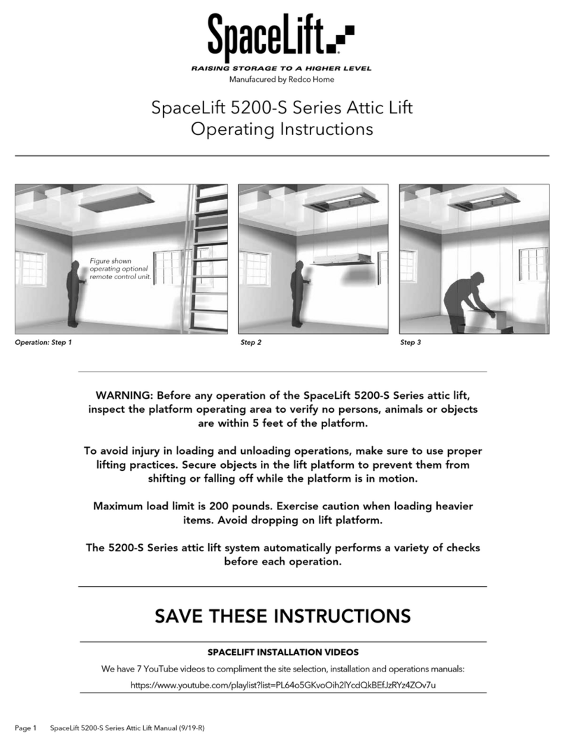
SpaceLift 5200 Series Attic Lift
Operating Instructions
WARNING: Before any operation of t e SpaceLift
5200 Series attic lift system, inspect t e platform
operating area to verify no persons, animals or
objects are wit in 5 feet of t e platform.
To avoid injury in loading and unloading operations,
make sure to use proper lifting practices. Secure
objects in t e lift platform to prevent t em from
s ifting or falling off w ile t e platform is in motion.
Maximum load limit is 200 pounds.
T e 5200 Series attic lift system automatically
performs a variety of c ecks before eac operation.
FIRST READ: NORMAL SEQUENCE OF
OPERATION
With lift in the fully stowed UP position the Remote
Control Unit will display only a Down Button. When
stowed pressing the Up Button will do nothing.
Pressing and holding the Down Button will start
the following sequence:
•The microprocessor weighs the tray. Only if the
tray has a load of less than 200 pounds will it be
allowed to move downward. If the load exceeds
200 pounds both arrows will display RED indicat-
ing an error.
•When the load is less than 200 pounds the tray
will start moving downward a short distance then
stop momentarily. As long as the Down Button
is continuously pressed the tray will continue
traveling downward at the normal run speed.
The tray will continue down until it approaches
the bottom limit where it will decelerate stop
and automatically slowly settle onto the floor
(provided bottom limit is set correctly).
•With tray on the floor only the Up Button will be
illuminated green indicating only upward travel
is possible. Pressing the Down Button will do
nothing.
Pressing and holding the Up Button starts the
following sequence:
•Tray will slowly lift off the floor allowing the micro-
processor to weigh the load. If the load exceeds
200 pounds the tray will lower back to floor level
and the Remote Control Unit buttons will show
RED indicating an error.
•Provided load is 200 pounds or less the tray will
accelerate to normal run speed going up until tray
is near the top where it will decelerate and stop
momentarily. Then continue slowly up to the stow
position. When stowed the Remote Control Unit will
display one GREEN Down Button indicating only
downward motion possible.
While traveling Up or Down:
•If the tray is stopped by the operator releasing a
travel button at any point between the “stowed”
and “on floor” positions both Remote Control Unit
arrows will show GREEN indicating travel is possible
either Down or Up.
•While tray is moving upward or downward the load
management system continuously monitors the load
and drive motor in order to detect an imbalance
overload or motor over current. If any of these errors
occur both arrows on remote will display RED.
After a few seconds arrow indicators will revert to
green indicating travel may resume.
NOTE: It is up to t e operator to determine
w et er or not any condition still exists t at
would generate anot er error (i.e. an overload
or imbalance).
Step 2 Step 3
Operation: Step 1

Page 8 SpaceLift 5200 Series Attic Lift Manual (10/14)
WARNING: Before any operation of t e SpaceLift
5200 Series attic lift system inspect t e platform
operating area to verify no persons, animals or
objects are wit in 5 feet of t e platform.
To avoid injury in loading and unloading operations,
make sure to use proper lifting practices. Secure
objects in t e lift platform to prevent t em from
s ifting or falling off w ile t e platform is in
motion. Maximum load limit is 200 pounds.
T e 5200 Series attic lift system automatically
performs a variety of c ecks before eac operation.
STEP 1. Turn on Remote Control Unit with Key.
•Up/Down Buttons – Arrows display GREEN to
indicate directions possible (i.e. stowed lift will
only go down).
•Obstacle Detection – If lift hits obstruction both
arrows display RED.
STEP 2. Use the Down Button to lower the cargo lift
platform to the lower level landing position.
STEP 3. Load the lift platform with items to be trans-
ported. Weight of items should be centered in tray.
Maximum load must be limited to 200 pounds per
trip. Be sure objects are secured to prevent load shift-
ing during lift operations.
STEP 4. Depress and hold the Up Button until the lift
cycle is complete. To halt operation release the but-
ton any time during the lift cycle.
STEP 5. Unload lift platform.
STEP 6. Turn Key OFF when lift operations are complete.
NOTE: If power is lost during operation the lift will
stop. When power is restored depress the Up
Button and return the lift to the fully stowed and
locked position. This enables the system to reset to
assure consistent operation.
WARNING: W en using t e cargo lift system
Remote Control Unit, keep t e lift platform in sig t
until completely stopped in eit er t e bottom or
top position. DO NOT allow c ildren to play under
or near t e lift platform.
WARNING: T e lift platform moves rapidly.
Keep pat clear.
SAVE THESE INSTRUCTIONS
Contacting SpaceLift Products
If your product fails during the warranty period and the
product documentation does not solve the problem you
may receive support by:
1. Check Model 5200 Series FAQ on the SpaceLift
website.
2. Contact the dealer from whom you purchased.
3. Use SpaceLift website Contact form for inquiry.
Before contacting your dealer or SpaceLift Products
have the following:
•Product serial number
•Product model name and model number
•Detailed notes for questions
SpaceLift 5200 Series Attic Lift
Operating Instructions
Step 4
Step 5
Step 2 Step 3
Operation: Step 1
SpaceLiftProducts.com
© 2014 SpaceLift Products, Inc All rights reserved (10/14)

Extent of Limited Warranty
SpaceLift Products Inc. warrants that the cargo lift
product will be free from defects in material and work-
manship for two years. SpaceLift Products does not
warrant that the operation of the product will be unin-
terrupted or error free.
This limited warranty covers only those defects that
arise as a result of normal use of the product and does
not cover any other problems including those that arise
as a result of: (i) improper maintenance or modification;
(ii) operation outside the product’s specifications; or (iii)
unauthorized modification or misuse.
If SpaceLift Products receives during the applicable
warranty period notice of a defect in any product
which is covered by this warranty SpaceLift Products
shall either repair or replace the product at its sole dis-
cretion and option.
Limitations of Warranty
TO THE EXTENT ALLOWED BY LOCAL LAW NEI-
THER SPACELIFT PRODUCTS NOR ITS THIRD PARTY
SUPPLIERS MAKES ANY OTHER WARRANTY OR
CONDITION OF ANY KIND WHETHER EXPRESS OR
IMPLIED WARRANTIES OR CONDITIONS OF MER-
CHANTABILITY SATISFACTORY QUALITY AND FIT-
NESS FOR A PARTICULAR PURPOSE.
Limitations of Liability
To the extent allowed by local law the remedies pro-
vided in this Limited Warranty Statement are the cus-
tomer’s sole and exclusive remedies.
TO THE EXTENT ALLOWED BY LOCAL LAW EXCEPT
FOR THE OBLIGATIONS SPECIFICALLY SET FORTH
IN THIS WARRANTY STATEMENT IN NO EVENT
SHALL SPACELIFT PRODUCTS OR ITS THIRD PARTY
SUPPLIERS BE LIABLE FOR DIRECT INDIRECT SPE-
CIAL INCIDENTAL OR CONSEQUENTIAL DAMAGES
WHETHER BASED ON CONTRACT TORT OR ANY
OTHER LEGAL THEORY AND WHETHER ADVISED OF
THE POSSIBILITY OF SUCH DAMAGES.
Local Law
This Limited Warranty Statement gives the customer
specific legal rights. The customer may also have other
rights which vary from state to state in the United
States from province to province in Canada and from
country to country elsewhere in the world.
To the extent that this Limited Warranty Statement is
inconsistent with local law this Statement shall be
deemed modified to be consistent with such local law.
Under such local law certain disclaimers and limitations
of this Warranty Statement may not apply to the cus-
tomer. For example some states in the United States
as well as some governments outside the united States
(including provinces in Canada) may: (i) preclude the
disclaimers and limitations in this Warranty Statement
from limiting the statutory rights of a consumer (e.g.
United Kingdom); (ii) otherwise restrict the ability of a
manufacturer to enforce such disclaimers or limitations;
or (iii) grant the customer additional warranty rights
specify the duration of implied warranties which the
manufacturer cannot disclaim or allow limitations on
the duration of implied warranties.
THE TERMS IN THIS WARRANTY STATEMENT
EXCEPT TO THE EXTENT LAWFULLY PERMITTED DO
NOT EXCLUDE RESTRICT OR MODIFY AND ARE IN
ADDITION TO THE MANDATORY STATUTORY
RIGHTS APPLICABLE TO THE SALE OF THE
SPACELIFT PRODUCTS TO SUCH CUSTOMERS.
Register Immediately Online to Initiate
Your Warranty:
SpaceLiftProducts.com/warranty
Or use the SpaceLift Warranty Card provided.
Protected by U.S. Patent No. 8 292 031.
SpaceLiftProducts.com
Limited Warranty
SpaceLift Products Model 5200 Series Lift System
Page 9 SpaceLift 5200 Series Attic Lift Manual (10/14) © 2014 SpaceLift Products, Inc All rights reserved
This manual suits for next models
2
Table of contents
Other SpaceLift Lifting System manuals
Popular Lifting System manuals by other brands

Snap-on Equipment
Snap-on Equipment EELS542A Installation, operation & maintenance manual

Titan Lifts
Titan Lifts RJ-6K-HP Installation, operation & maintenance manual
Bishamon
Bishamon LV50W Operation and service manual
ANthony
ANthony AST-1500 installation manual

Screen Technics
Screen Technics INTERFIT Vertical Up Lift instructions

Harmar Mobility
Harmar Mobility AL625 Installation & owner's manual
