SpaceraiL 5.1 User manual

Instruction Manual Level 5.1

2
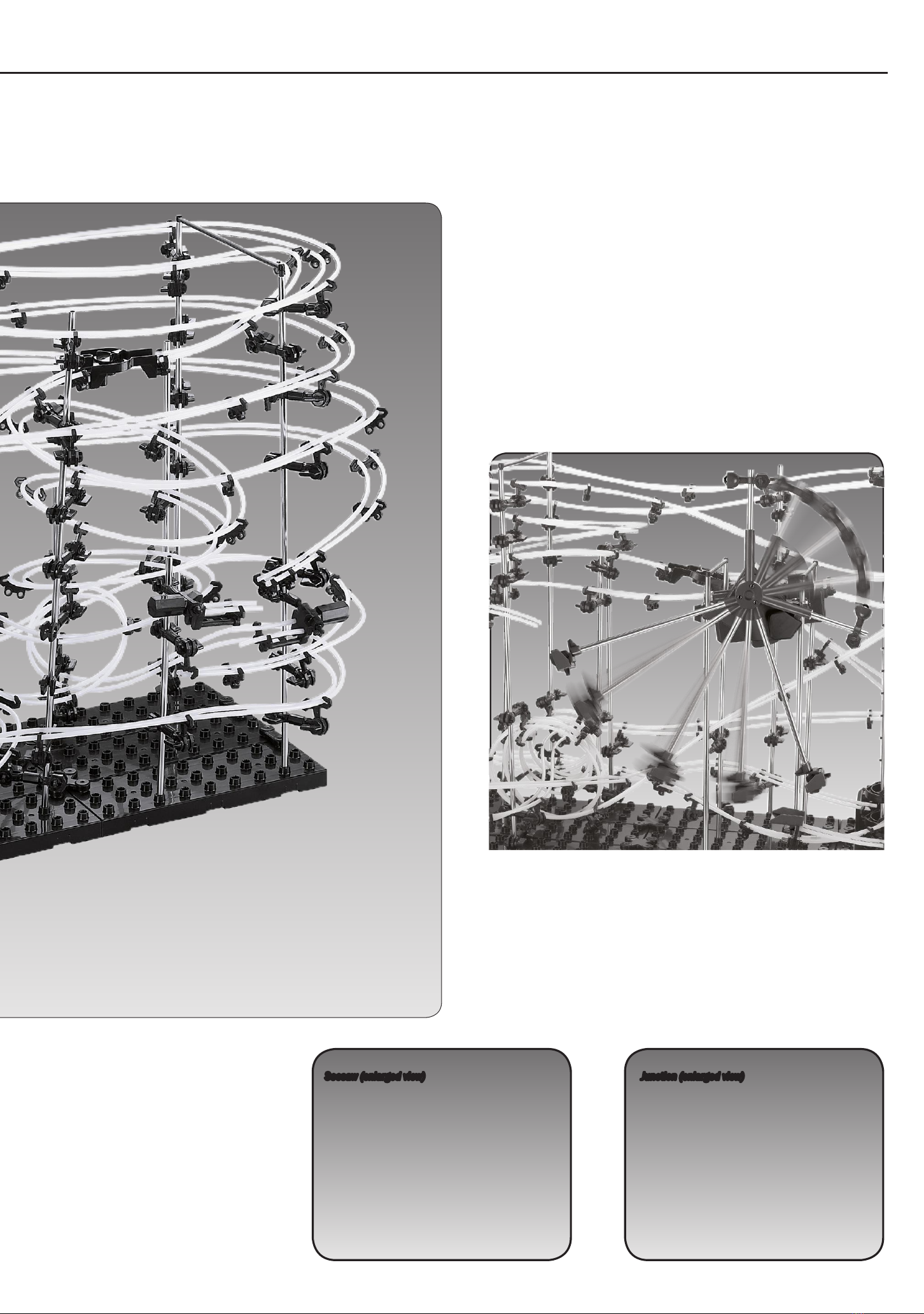
Elevator (enlargedview)
fg. 1
Quadloop(enlargedview)
SpaceRail Level 5.1
3
Table of Contents
Pendulum(enlargedview)
Seesaw(enlargedview)
Figure1..................................................... P. 2-3
Figure2-6..................................................... P. 4
PartsList...................................................... P. 5
Assemblyofthebaseplate.............................P. 6
Assemblyofthearms.................................... P. 6
Assemblyoftheseesaw..............................P. 6-7
Assemblyoftheelevator................................P. 7
Assemblyofthependulumandstarterkit.....P. 8-9
Assemblyofthebaseplate, gearbox,
pendulumandstarterkit.............................P. 8-9
Locationsof theelevatorrings.....................P. 8-9
Positionsofarms........................................P. 8-9
Rail assemblysteps.................................P. 10-11
Rail mounting.............................................. P. 12
Loopmounting............................................ P. 12
Elevatormounting(entryandexit).................P. 13
ConstructyourownStarCoasterdesigns........P. 14
Assembledproduct.......................................P. 15
Warnings.....................................................P. 16
Junction(enlargedview)
SpaceRail is a spectacular marble-run coaster that guarantees high-speed action rides cosisting of wild rotations, daring loop-
the-loops and spectacular swivel motions.These ball roller coasters are an ultimate challenge for teenagers and adult
enthusiasts alike. SpaceRails are available in different sizes and different levels of difficulty.

4
fg. 2 (front)
fg. 3 (left) fg. 4 (top)
fg. 6 (back)
fg. 5 (right)
These pictures show
the SpaceRail Level
5.1 from several
different viewpoints.
This is very helpful to
reference during
assembly.

[B2] Baseholder (big) [B3] Baseholder (small) [G2] Gearboxsocket
[S6] ConnectingpieceA(176mm)
[S7] ConnectingpieceB(154mm)
[S8] ConnectingpieceC(90mm)
Steel balls
[R2] Rail joining [Ex2] Pendulum [Ex3] Starter Kit [Ex4] Breakcover for starterkit [Ex5] Ball catcher [Ex6] Counterweight [Ex7] Pendulumtrayfor steel balls
5
Parts List
Pliers
Use1 xC/ LR14 battery(not included).
Handlethecomponents withcareto prevent themfromgettinglost.
Tapemeasureorfoldingruler
Toolsforinstallation:
Partslist
[B1]
[A1]
[G1]
[B2] [B3] [S6] 176mm [S7] 154mm [S8] 90mm [G2]
[R2] [Ex2] [Ex3] [Ex4] [Ex5] [Ex6] [Ex7]
[E1] [E2] [E3] [Ex1] [P1]
[A2] [A3] [A4] [A5] [A6]
[S2] 300mm [S3] 200mm [S4] 159mm [S5] 65mm [R1] 32.000mm[S1] 391mm
[B1] Baseplate
[A1] Arm
[G1] Gear Box [E1] Elevator helix [E2] Elevator ring
[A2] ArmholderA [A3] Armtube [A4] ArmholderB [A5] Armwrench [A6] Rail stand
[S1] Shaft 391mm [S2] Shaft 300mm [S3] Shaft 200mm [S4] Shaft 159mm [S5] Shaft65mm [R1] Rail (32,000mm)
12x
80x
1x
6x
10x
80x
16x
4x
1x
80x
3x
1x
1x
85x
1x
3x
1x
165x
2x
2x
1x
90x
2x
1x
1x
5x
1x
11x 10x 2x 1x 1x 2x
[E3] Elevatorcover [P1] Junction[Ex1] Seesaw

6
Assemblyofbaseplate
1. Assemblethebaseplate
(12 pieces). Payattentionto
aproperseatingof theclips
and slots (fg. 01)
2. Fastenthebaseholders
(B2 +B3) inthecorrect
positions (fg. 01-2)
1
2
3
Assemblyofarms
1. Assemblethearms
accordingtofg. 02. Caution:
ArmholderA(A2) +arm
holderB(A4) aredifferent.
73arms areneededforthe
completeset-upof„Star
CoasterLevel 5“
2. Insert thearmwrenchinto
thearmholderAandturnit
by90 degrees tof xthearm
(fg. 03). Note:Tomodifythe
angleofthearm, releasethe
fxationfrst
3. Attachthearmtotheshaft
(fg. 04): Insert shaft intothe
armholderBandturnthe
armwrenchby90 degrees
tof xthearm(fg. 04). Note:
To modifythe angleof the
arm, releasethefxationfrst
Assemblyofseesaw
Insert 4x55mmrail intothe
holes of theseesaw. Then
attachtherail standtothe
seesaw(fg. 05)
Assembly of base plate, arms & seesaw
1
01
[B2] Baseholder(big)
[B3] Baseholder(small)
[B1] Baseplate
02
2[A3] Armtube
[A4] ArmholderB
Top-downview
Top-downview
[A2] Armholder A
[A5] Armwrench
Insertshaft intothearmholder B. Donot
applyforceinordertoavoiddamages
[A1] Arm
Note: When turningthearmwrench, makesurenot
to change the right positionof thearm
Note: When turningthearmwrench, makesurenot
to change the right positionof thearm. Refer to the
assemblyof arms (page E1-E4)
03
04
05
01-2
[A6] Rail stand
[Ex1]Seesaw
Approx. 55mm
[A6] Rail stand
[A6] Rail stand
[A6] Rail stand
[A6] Rail stand
[E2] Elevator ring
[E2] Elevator ring
[E3] Elevator cover
[G1] Antrieb
[G1] Gearbox
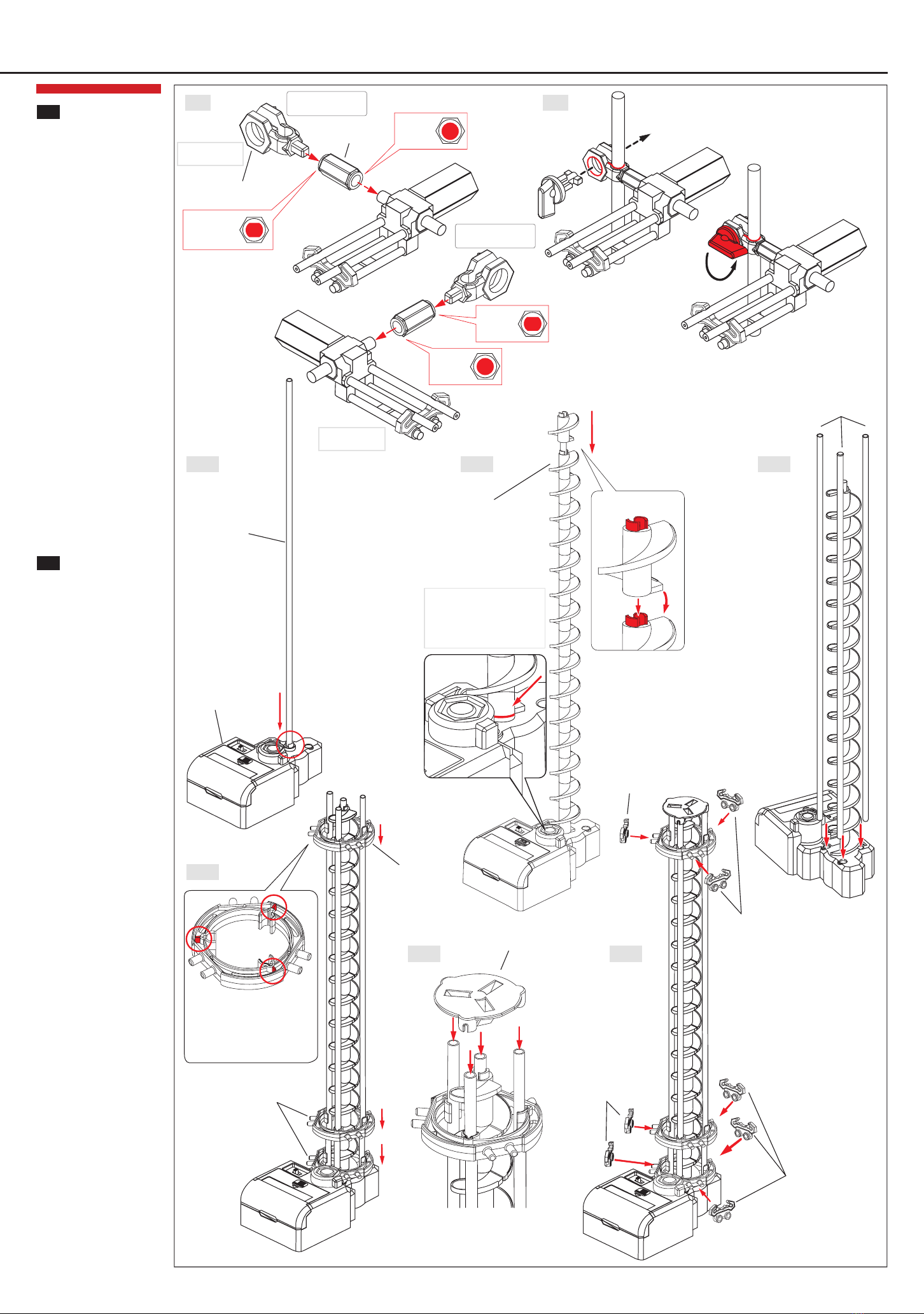
Assemblyoftheelevator
1. Insertthe391mmshaft into
thegearbox(fg. 08-1)
2. Slidetheelevator(16pcs)
ontotheshaft (fg. 08-2).
Insert shaft intobase(fg.
08-1). Pleasenotethecorrect
directionof rotation
3. Insert 3further391mmshafts
intotheexact pre-defned
positions onthegearbox(fg.
08-3)
4. Allowthe3 shafts to snapinto
place(pic. 08-4). Takecare
that theelevator rings are
properlylocated. Seepage8
+9 for theproper locations of
theelevatorrings
5. Insert the4 shafts intothe
elevatorcover(fg. 08-5).
Takecarethat theshafts are
properlylocated
6. Nowattach3 rail stands [A6]
totheelevatorring(fg. 08-6)
7
3
4
Assemblyofseesaw
Attachseesawtotheshaft
(fg.06+07)
1. Connect seesawwitharm
holderB(fg. 06)
2. Attacharmholder Btothe
shaft (fg.07). Refer tothe
assemblyof arms (page10
andfollowing). Insertarm
wrenchintoarmholderBand
turnit by90 degrees (fg. 03).
Note: To modifytheangle of the
arm, releasethefxationfrst
Assembly of base plate, arms & seesaw
06 07
08-1
08-4
08-5 08-6
08-2 08-3
[A3] Armtube
[A4] ArmholderB
mountrighthandside
mountlefthandside
Install 1pcs
Install 1pcs
Holeprofle
Lochprofl
Holeprofle
Holeprofle
Holeprofle Adjust seesawafter assemby
Note: Whenturningthearmwrench, makesurenot tochange
theright positionof thearm
[S1] Shaft 391mm
[S1] Shaft 391mm
[E1] Elevatorhelix
Avoidthat thereis a gap between
gearboxandelevatorhelix.
Otherwisetheelevatorwill not
operateproperly. Pleasenotethe
correct directionof rotation
Makesureconvexred parts point
up andeverythingis correctly
seated.
Assembly of gear box and base plate
[G1] Gearbox
[S6- S8] Connectingpiece
Connect withholes onbaseplate
Seesaw(turnright)
8
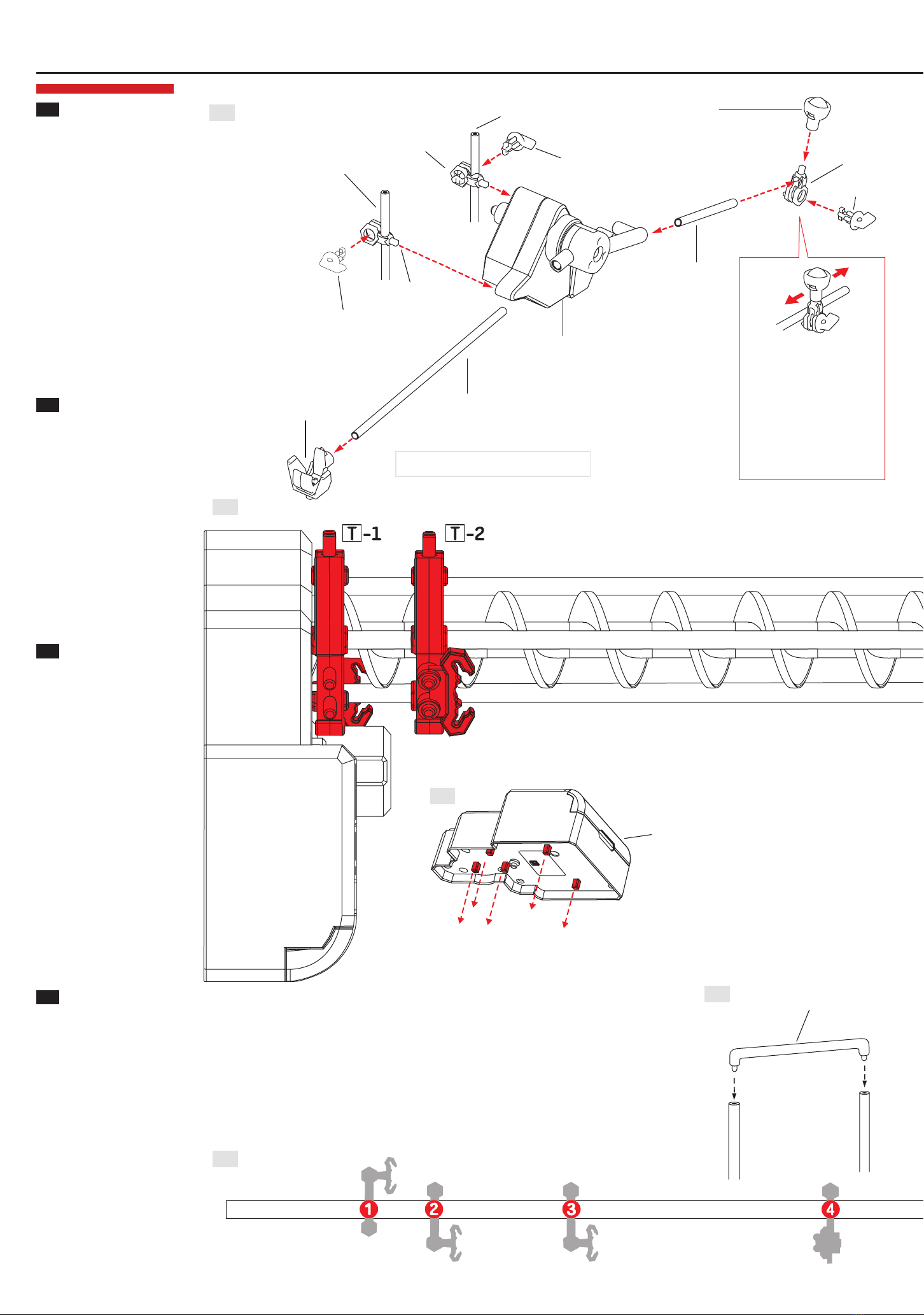
Installationofthependulum
andstarterkit
1. Connect attachment parts with
pendulum(f g. 09). Note: To modify
thepositionof armholder B, release
thefxationfrst
2. Connect attachment parts with
starter kit (fg. 10). Note: To modify
thepositionof armholder B, release
thefxationfrst
5
6
7
8
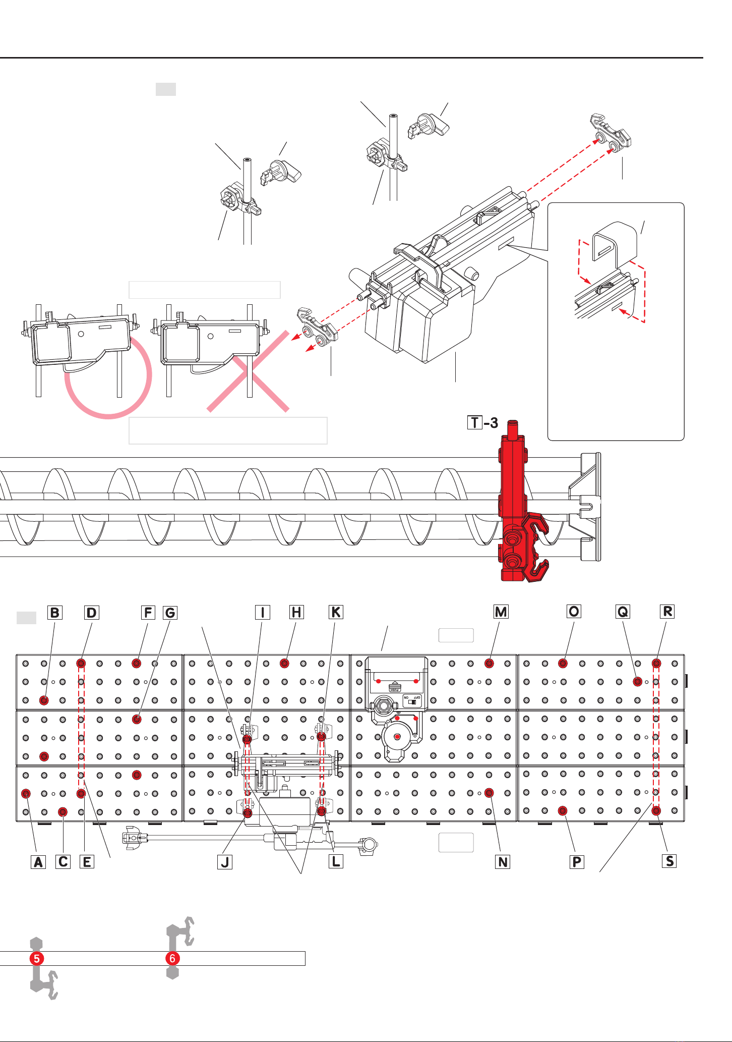
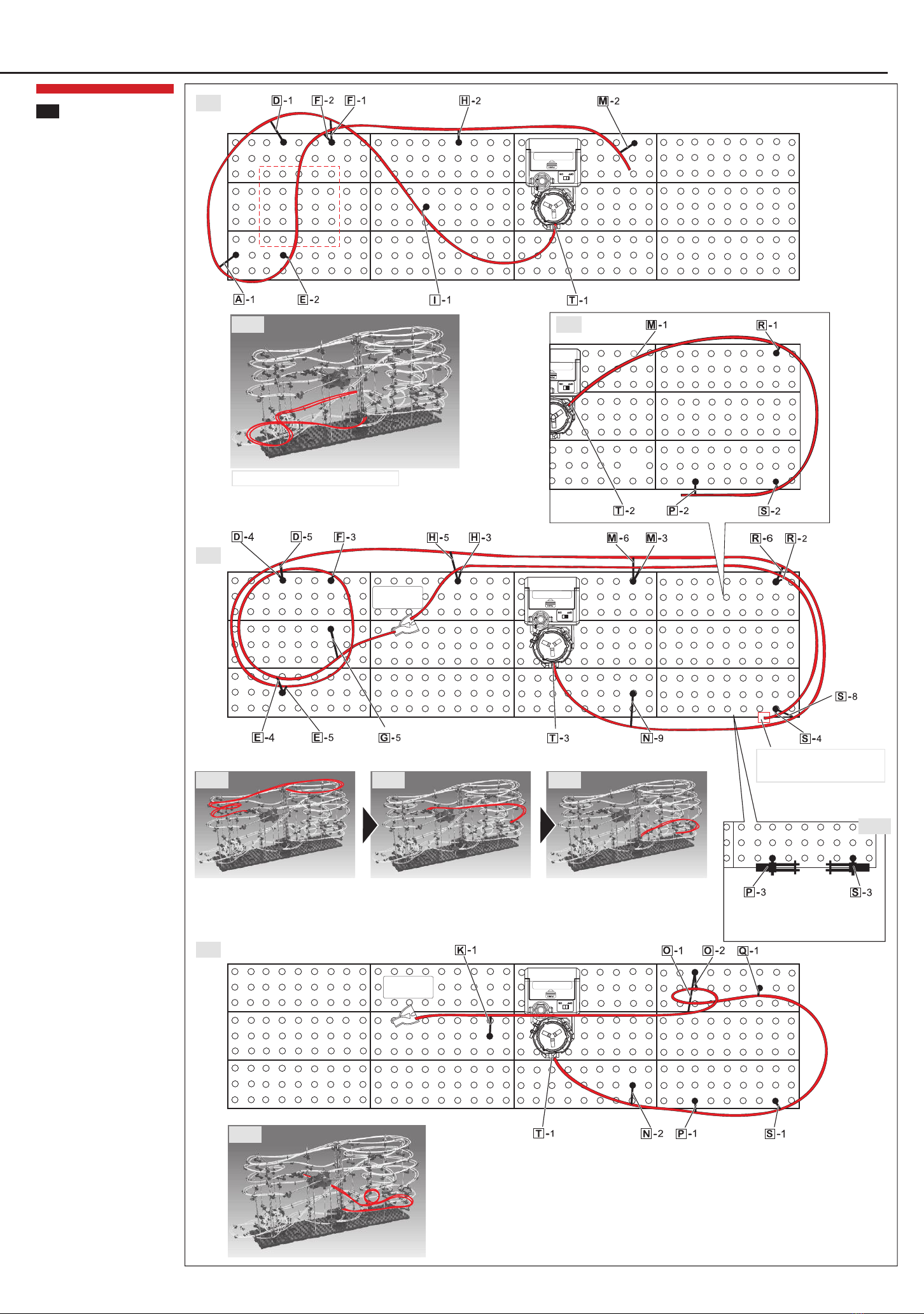
Locationsof theelevatorrings
Elevator(fg.11): Elevatorisshowninascale
of1:1.Attachtheelevatorringstotheexact
pre-defnedredpositions (T-1,T-2,T-3)
Attachthe5clipsat thebottomofthe
gearbox(seeredmarkings infg.12) to
theexactpre-defnedpositionsof thebase
plate(fg.13)
Installationofgearbox,
pendulumandstarterkit
Locationof pendulumand starter kit on
base(fg.13)
Attachpendulum(fg. 09) andstarterkit
(fg.10) tothebaseplate(fg. 13)
Gearboxlocationonbaseplate(fg. 13)
Attachthe5 clips at thebottomof the
gearbox(see redmarkings inf g. 12) to
the exact pre-def nedpositions of the
baseplate(fg.13)
Positionsofarms
Attachthearms totheshafts (fg.14).Picture
showsascaleof1:1
Attachthearms totheshafts (seeillustration
forarminstallationonpageE1-E4)
Attachconnectingpiecestoshafts(fg.15+13)
Inserttheshaftsintothebaseplate(fg.13)
09
11
12
14
15
[S2] Shaft 300mm
[S2] Shaft 300mm
[S5] Shaft 65mm
[S4] Shaft 159mm
[A4] Armholder B
[A4] Armholder B
[A4] Armholder B
[A5] Armwrench
[A5] Armwrench
[Ex5] Ball catcher
[Ex6] Counterweight
[Ex2] Pendulum
[A5] Armwrench
Referto theassemblyof arms (fg. 04)
Thecounterweight positionis adjustable
on theshaft if the pendulumdoes
not workproperly.Note: Tomodifythe
positionof counterweight, releasethe
fxationfrst
Referto theassemblyof arms (fg. 04)
Attachstarterkit (armholder B) totheshaft andcreateaslope, sothat
thesteel balls canrun smoothly
[S1] Shaft 391mm
9
10
13
[S2] Shaft 300mm
[S2] Shaft 300mm
[A4] Armholder B
[A4] Armholder B
[A6] Rail stand
[A6] Rail stand
[Ex3] StarterKit
[A5] Armwrench
[A5] Armwrench
Pendulum
[Ex4] Brakecoverforstarter kit
Connect rails withtheentryof thestarter kit
and makef neadjustments to slowdownthe
speedof thesteel balls (balls will rebound if
toofast). Attachthebeakcovertothestarter
kit as shownin theillustration
Positionfor connectingpieceB
(154mm) [S7] Positionfor connectingpieceC
(90mm) [S8] Positionfor connectingpieceA
(176mm) [S6]
StarterKit Elevator
Vorderseite
Front
Back

Assembly of rails
JunctionA
[Ex7] Pendulumtrayforsteel balls
10
16
17
18
JunctionA
Rail assemblysteps
This ball roller coasterprovides 3
exits (start) and5 entries (end).
Pleasenotefg. 16-22andthe
illustrations onpage2-4 during
assembly
Install rail standstogetherwith
therails (fg. 26)
1. Fromelevatorexit (start) tothe
junctionAentry(end): Install 2
x61cmrails (fg. 16-1)
2. FromthejunctionAexit(start) to
thestarterkitentry(end):Install
2x117cmrails(fg.16-2)
Connect rails withtheentryof
thestarter kit andmakefne
adjustments to slowdownthe
speedof thesteel balls (balls will
rebound if toofast)
3. Fromstarterkit exit(start) to
theball catcher(end): Install 2
x58cmrails (fg. 16-3)
4. Frompendulumtrayforsteel
balls (start) toelevator entry
(end): Install 2 x40cmrails
(fg. 16-4)
5. FromthejunctionAexit (start)
tothelowerelevatorentry
(end): Install 2 x270cmrails
(fg. 17)
6a.Fromtheupperelevatorexit
(start) tobehindthetraverse
loops: Install 2 x507cmrails
(fg. 18). Caution: DoNOTcut
therails here(sectionwill be
continued as showninfg. 19)
9
Install 2x61cmrails Install 2x117cmrails Install 2x58cmrails Install 2x40cmrails
Do NOTcut therails here(section will be continued as shown in fg. 19)
16-1 16-2 16-3 16-4
Fromelevator exit (start) tothejunctionAentry(end) FromthejunctionAexit (start) tothestarter kit entry(end) Fromstarter kit exit (start) totheball catcher (end) Frompendulumtrayfor steel balls (start) to elevator entry (end)
Rail trackuntil junction. Install junctionat theveryendof theinstallationprocedure Releasearmtube[A3] beforemountingtherails
Assembly of rails
Rail assemblysteps
6b.Fig. 19 shows thecontinuation
of fg. 18: Continuedsection
startsbehindthetraverseloops
and ends at thelower elevator
entry(fg. 19)
7. Fromupperelevator exit (start)
tothejunctionBentry(end):
Install 2 x235cmrails (fg.
20-1)
8. FromjunctionBtotheupper
seesaw: Install 2x96cmrails
(fg. 20-2)
9. Fromlowerseesaw(start)
tothemiddleelevator entry:
Install 2 x80cmrails (fg. 21-1)
10.FromjunctionB(start) tothe
middleelevatorentry(end):
Install 2 x142cmrails (fg. 22
+22-1)
9
19-1
20-1 20-2
20-3
21-1
22-1
11
19
21
20
22
Fig. 19 +19-1showthecontinuationof fg. 18
Fromupper elevator exit(start) tothejunctionBentry
Install 2 x235cmrails (f g. 20-1) Install 2 x96cmrails (fg. 20-2) Install 2 x80cmrails (f g. 21-1)
Correct assemblyof seesaw(fg. 20-3)
FromjunctionBto theupperseesaw Fromlower seesaw(start) to themiddleelevator entry Insert rail stand at the end of the rail to
ensurebestseesawstability
JunctionB
JunctionB

12
Installationoftherails
Attachmentofrailstoarmsandshafts(fg.
23+24)
Attachrail toarm(fg.23)
Rail joining(fg.25)
Adjustandconnecttherails.Inserttherail
joinings[R2]intotheholesatthecenterof
therails(fg.25)
Informatonsaboutrail stands(fg.26)
Thedistancebetweenthearms shouldbe
between8to10cmtoensurebeststability.
Whenthedistanceis larger,rail stands [A6]
havetobeinstalled
Attachrail stands insteepsections and
elevatorentry/exitpointstoensurebest
stabilityoftherails
Steepsections(fg.27)
Install thearmsinaninclinedpositionto
eachothertocreatesteepsections,sothat
thesteel ballscanrunsmoothly(fg.27)
Installationofaloop
Ensurethe steel balls runningsmoothly
(fg.28)
Thediameter of the outer loopshould
havetwice thediameter of theinner loop
Important informationfor theassemblyof
loops (fg. 29)
Rails havetoformacircle that remains
inanupright positiontoensurethesteel
balls runningsmoothly(f g. 29)
Installationof aloop (f g. 30)
Whenmountingloops, thesecondloop
has to besmaller thanthef rst loop to
ensurethe steel balls runningsmoothly
Installationof pendulumtrayandjunction
(fg.31-1+31-2)
Insert rail stands into thejunction(fg.
31-1)
Simplycut therails to thecorrect length
(seeenlargedpictureontheright)
Insert rails into thependulumtray(f g.
31-2)
10
11
Assembly of rails
23 24
25
26
27
28 29 30
[A1] Arm
[R1] Rail
Insert rails intoarm
Install thearms inaninclinedposition
toeachothertocreatesteepsections
-
Pleaserefertotheillustrationabovefor
diameters of aquadloop (increasediameter
witheachadditional loop)
Userail stands likerailwayties
Thedistancebetweenthearms shouldbebetween8 to10cm. When
thedistanceis larger, rail stands [A6] havetobeinstalled
[R1] Rail [R1] Rail
[R2] Rail joining
Height
Innerlooping
Cut here
Innerlooping
Outer looping
[A6] Rail stand
[A6] Rail stand
[P1] Junction
[Ex7] Pendulumtrayfor steel balls
31-1
31-2
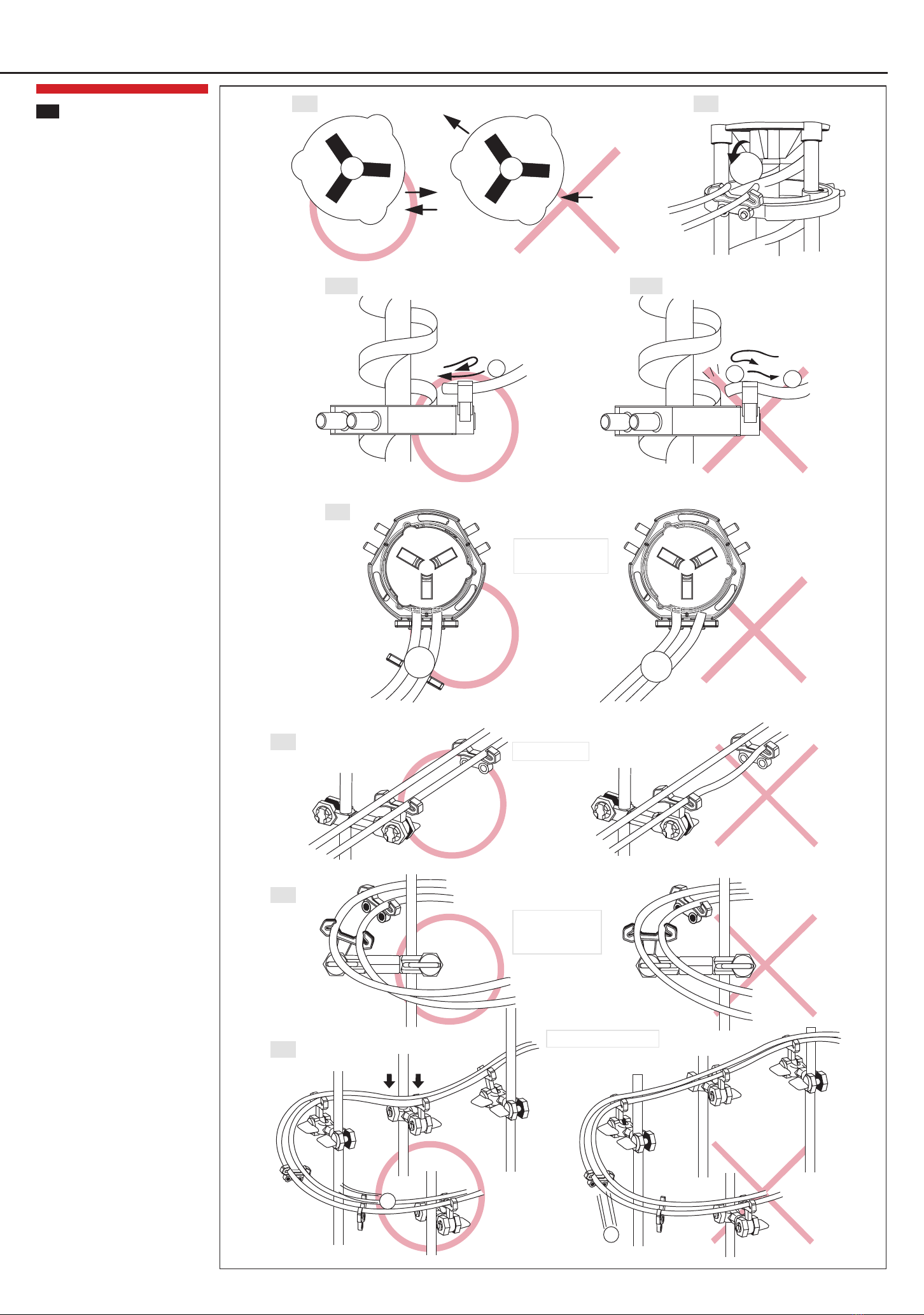
Installationofelevator(entry&exit)
Important informationfortheassemblyof
elevatorentryandexit (fg.32)
Steel balls will not runcorrectlyif entry
andexitpoint inthesamedirection
Payattentiontoa proper installationof the
entryandexit(fg.33)
Install rails as closelyas possibletothe
entryandexit of theelevator to ensurethe
steel balls runningsmoothly(fg. 33)
Payattentiontoa correct angleof therails
whenthesteel balls entertheelevator (f g.
34-1,34-2,35)
Makesurethesteel balls enter theelevator
slowly.Otherwisetheywill reboundandfall
off therails (fg. 34-1)
Steel balls that enter theelevator may
reboundandthownbackontotherails
afterhittingthehelix. Payparticular
attentionhereto thecorrect seatingof the
rails.Otherwisethesteel ballswill stopand
cannot re-entertheelevator(fg.34-2)
At theentryall rails must beat right angles
totheelevator(fg. 35)
Distancebetweenrails (fg. 36)
Install therail standtokeeprails parallel
(fg. 36)
Curves (fg. 37 +38)
Curves needtobeassembledinacertain
angletoprevent steel balls frommissing
theturn(fg. 37). If steel balls miss the
turn, speedhas to bereducedright before
thecurve
Adjust rails to reducespeed of thesteel
balls (fg. 38)
12
Entry
Entry
Exit
Exit
13
Assembly of rails
32 33
35
36
37
38
All rails must beat right
angles totheelevator
Keep rails parallel
Curves needto be
assembledina certain
angle
Adjust rails to reduce speed
34-1 34-2
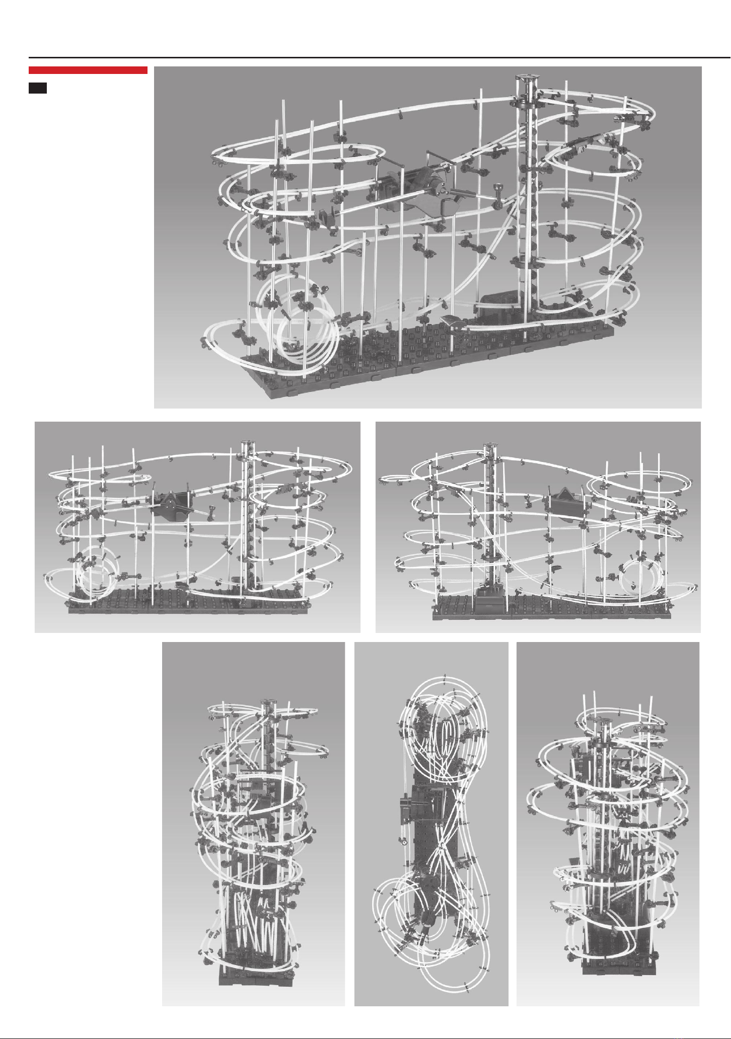
13 fg. 1 (diagonal)
fg. 2 (front)
fg. 4 (left) fg. 5 (top) fg. 6 (right)
fg. 3 (back)
14
Construct Your Own SpaceRail Designs
Construct your own
SpaceRail designs
Let the imagination run wild
and create your own
SpaceRail coasters.
Pictures 1-6 show another
alternative example with 6
base plates and the parts
from the Level 5.1.

Rail length16,000mm
Rail length10,000 mm
Rail length26,000mm
Rail length68,000 mm
Glowinthedark
15
Product Range
Level 2.1
Level 3.1
Level 4.2
Glow in the Dark
Level 9.1

Disposal Restrictions(WEEE)
Electrical andelectronicequipment shouldbedisposedseparatelyfromthehouseholdwaste. Takeyourunwantedequipmenttoyourlocal communitycollectionpoint. This requirement applies tomembercountries
of the EuropeanUnionas well as othernon-Europeancountries witha separate wastecollectionsystem. Neverthrowbatteries intonormal householdwaste, but disposeof discharged batteries at
thecollectionpoints providedforthat purpose(e.g. yourlocal toxicwastedisposal centre).
RecommendedAccessories: 1xC/LR14 battery1.5V
Insertingthebattery: Usea Phillips screwdriver toopenthebatterycompartment cover. Insert 1 xC/ LR14 batterywiththecorrect polarityandreplacethebatterycompartment cover.
Distributedby:
16
Safety Instructions – Keep After Reading
General SafetyInstructions
This ball roller coaster is NOTATOYandonlysuitablefor persons 14 years and older!
Warning: Readthemanual carefullybeforeusingtheball rollercoaster. Keepthemanual afterreading.
Always followexactlytherecommendations givenintheinstructions.
Errors and negligences inoperatingyour ball roller coaster canresult ininjuries and damageto
property. As manufacturers andvendors haveno inf uence ontheoperationand maintenanceof your
ball roller coaster, webringthesehazards expresslyto your attentionbut denyall further liability.
Keepawayfromchildren. Theball rollercoastercontains small parts. Chokinghazard.
Warning: Sharp edges - watchyour fngers.
Warning: Donot drapetherail around your neck, as this couldresult insuffocationor injury.
Strangulationhazard.
Keep thepackagingfor futurereferenceas it contains important information.
SafetyInstructionsDuringOperation
Movingparts area constant source of injury. Nevertouchmovingparts.
Keep hands, hair, looseclothingandfurther objects awayfrommovingparts.
Persons (includingchildren) withreducedphysical, sensoryor mental capabilities or lackof experience
arenot allowedtousethis ball roller coaster, unless theyaresupervisedbya personresponsiblefor
their safetyandabletogiveprofessional advicehowtheproduct shouldbeused.
Donot bendtheshafts and other parts to avoid injuryandensure safeoperation.
Keep fngers awayfromthemovingelevator toavoidinjury.
Onlyuseoriginal steel balls topreventdamageof theball rollercoaster.
Caution: Violent jamming(stopping) duringoperationmaydamagethemotor. Donot cumberthe
elevator.
Always storeand operatetheball roller coaster at asafeplace.
Besuretocheckbatteryregularlyto ensure aproper operationof theelevator.
Checkrails regularlyfor af rmseatingandadjust if necessary!
Protecttheball rollercoaster fromheatandsun.
Caution: To protect motor fromdamageandoverheating, donot operatethe ball roller coasterfor more
than 5hours at atime.
SafetyInstructionsForBatteries
Onlybatteries of thesameor equivalent typeas recommendedareto beused.
Exhaustedbatteries shouldberemovedfromtheball roller coaster.
Donot disposebatteries infre– batteries will explodeor leak.
Batteryis to beinsertedwiththecorrect polarity.
Non-rechargeablebatteries arenot tobe recharged.
Remove batteryif the ball roller coaster is not tobeusedfor anextendedperiodof time.
Besuretocheckbatteryregularlyto ensure aproper operationof theelevator.
Table of contents
Other SpaceraiL Toy manuals


Popular Toy manuals by other brands

Oregon Scientific
Oregon Scientific Smart Globe Discovery SG268 manual

Power Wheels
Power Wheels Jeep Safary 86250 Assembly manual

LEGO
LEGO Mindstorms NXT 8527 Building instructions

Fisher-Price
Fisher-Price iXL instructions

GRAUPNER
GRAUPNER POWERKAT X operating instructions

Protos
Protos MAX2 instruction manual


Mega Bloks
Mega Bloks SABAN'S Power Rangers MEGAFORCE Robo Knight VS.... Assembly instructions

Fisher-Price
Fisher-Price LOVING FAMILY H5790 instructions

Betzold
Betzold Kiga-Konstruktion 761415 manual

Twister
Twister Micro Twister quick guide

miniland
miniland emotions buddy manual

Mattel
Mattel HotWheels FTH79 instructions