SpaceraiL Spacewarp Level 2.1 User manual

Instruction Manual Level 2.1

SpaceRail Level 2.1
2
Table of Contents
Figure1............................................P. 2
Figure2-6.........................................P. 3
PartsList..........................................P. 4
Assemblyofthebaseplate............P.4
Assemblyofthearms......................P.4
Assemblyoftheseesaw..................P. 4
Assemblyoftheelevator.................P. 5
Assemblyofshaftsandarms.....P. 6-7
Installationofbaseplateandshafts........P.6-7
Installationofgearbox...............................P. 6-7
Rail assemblysteps.....................................P. 8
Rail mounting...........................................P. 9-10
Loopmounting............................................P. 11
Elevatormounting(entryandexit).............P. 11
Warnings.....................................................P.12
SpaceRail is a spectacular marble roller coaster that guarantees high-speed action rides
consisting of wild rotations, daring loops and seesaw swivel stunts. These marble roller
coasters are an ultimate challenge for teenagers and adult enthusiasts alike. They are
available in different sizes and with different levels of difficulty.
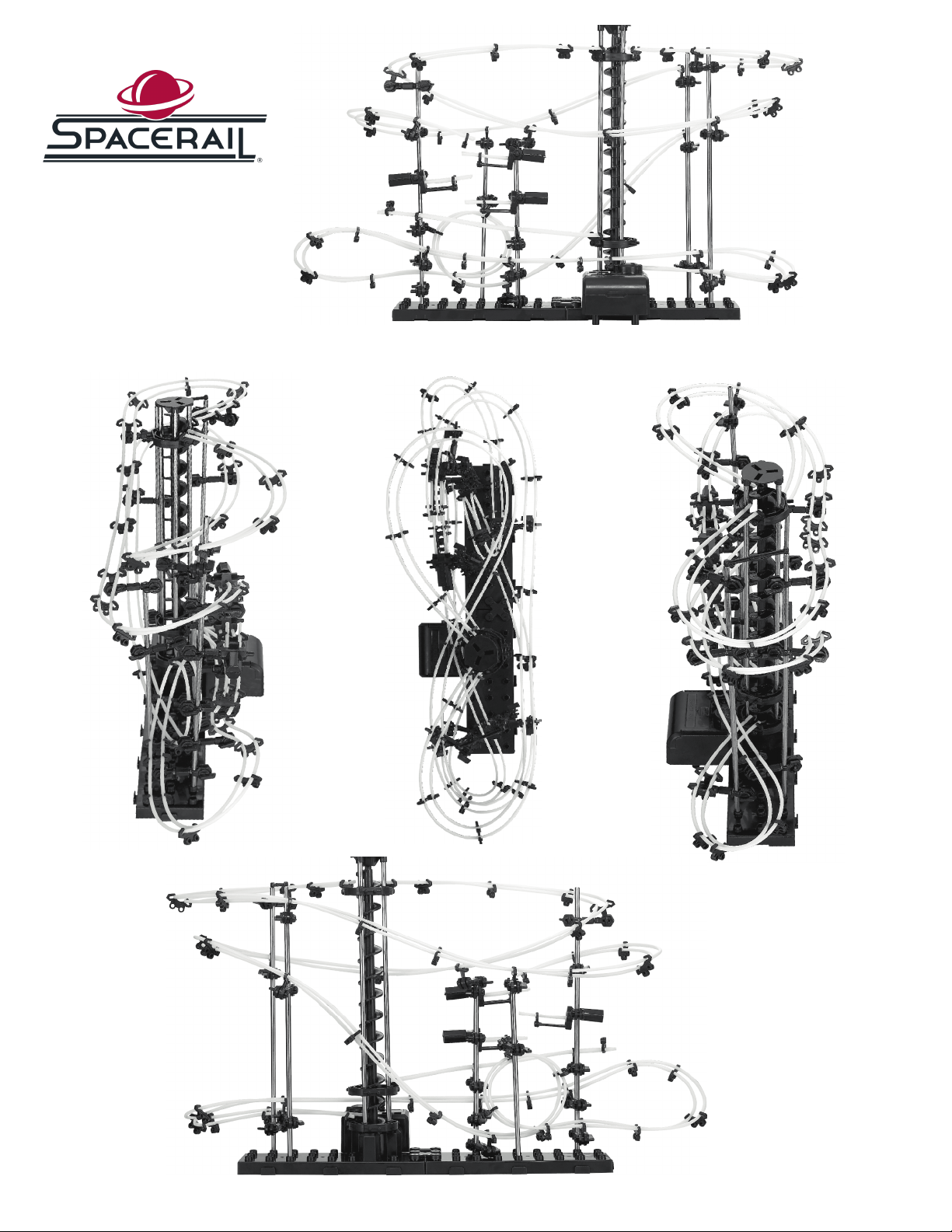
SpaceRail
Level 2.1
These images show the fully built model of Spacerail Level 2.1. Correct fitting and interaction of all
components and connections has a significant influence on the stability and strength of the complete
construction.
SeeSaw Stunt Loop Elevator
3
These images show the
SpaceRail Level 2.1 from
multiple angles. They will
be helpful while you are
building.
Front
Left Top Right
Back
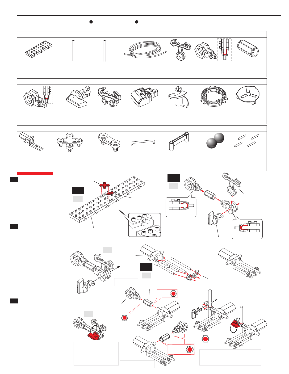
Use1 xC/ LR14 battery(notincluded). Handlethecomponents with careto prevent themfromgettinglost.
Partslist
4
[B1]
[A4]
[F1] [B2] [B3] [S3] [G2] [R2]
[A6] [G1] [E1] [E2] [E3]
[A5]
[S1] 300mm [S2] 200mm [R1] 10.000mm [A1] [A2] [A3]
[B1] Baseplate
[A4] ArmholderB
[F1] Seesaw
[A5] Armwrench
[B2] Baseholder(big)
[A6] Rail stand
[B3] Baseholder (small)
[G1] Gearbox
[S3] Connectingpiece
[E1] Elevator helix
[G2] Gearboxsocket
[E2] Elevatorring
Steel balls
[E3] Elevator cover
[R2] Rail joining
[S1] Shaft 300mm [A1] Arm[S2] Shaft 200mm [R1] Rail 10,000mm [A2] Armholder A [A3] Armtube
2x
20x
3x
7x
37x
1x
2x
40x
1x
1x
1x
1x
17x
12x
1x
17x
3x
2x
20x
1x
4x
[B2] Baseholder (big)
[B3]Baseholder(small)
[F1] Seesaw
[A4] ArmholderB
[A3]Armtube
[A6] Rail stand
Note: Whenturningthearmwrench, makesurenot to
changetheright position of thearm
Install 2pcs
Mount lefthandside
Note: Whenturningthearmwrench,
makesurenot tochangetheright
positionof the arm
Approx. 55mm
[A5] Armwrench
[A1] Arm
[A4] ArmhalterB
[A4] Armholder B
Holeprofle
Holeprofle
Holeprofle
Holeprofle
[A2] ArmhalterA
[A2] Armholder A
Top-downview
Top-downview
[A3] Armtube
[B1] Baseplate
-
-
Assemblyof baseplate
1. Assemblethebaseplate(6 pieces).
Payattentiontoa proper seatingof the
clips and slots (f g. 01)
2. Fastenthebaseholders (B2 +B3) inthe
correct positions (f g. 01)
1
2
3
01
02
03
04
05
1
2
3
Assemblyof arms
1. Assemblethearms accordingto f g. 02.
Caution: Armholder A(A2) +armholder B
(A4) aredifferent. 17 arms areneeded for the
completeset-upof „Star Coaster Level 2“
2. Insertthearmwrenchintothearmholder
Aand turnit by90 degrees to f xthe arm
(f g. 03)
Note:Tomodifytheangleofthearm, releasethe
fxationfrst
Assemblyof seesaw
1. Inserttheseesawinto therail stand
(f g. 04)
2. Inserttheseesawinto armholder B, then
attachthecompletecomponent tothe
shaft(fg. 05). Refer totheassemblyof
arms (f g. 02+03). Note: To modifythe
angleof thearm, release the fxation frst
Mount righthandside
Install 1pc
Parts List
Tools for installation Pliers Tape Measure
5
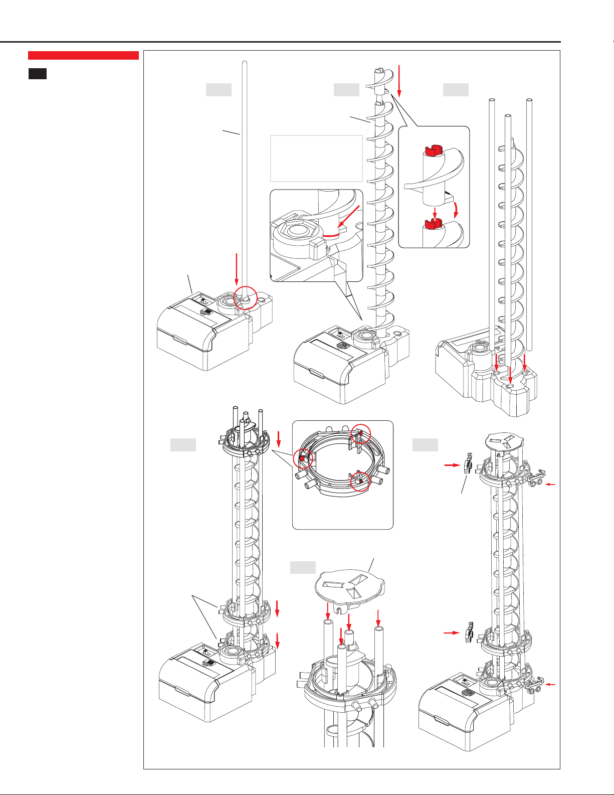
Assemblyoftheelevator
1. Insert the300mmshaftintothe
gearbox(fg. 06-1)
2. Slidetheelevator(12pcs) onto
the300mmshaft(fg. 06-2
Pleasenotethecorrectdirection
of rotation
3. Insert 3 further300mmshafts
intotheexact pre-defned
positionsonthegearbox(fg. 06-3)
4. Allowthe3 shafts tosnap into
place(pic. 06-4). Takecarethat
theelevator rings areproperly
located
Seepages 6+7 fortheproper
locations of theelevatorrings
5. Insert the4 shafts into the
elevatorcover (fg. 06-5). Take
carethat theshafts are properly
located
6. Nowattach3 rail stands [A6] to
theelevatorring(fg. 06-6)
06-1 06-2 06-3
06-4
06-5
06-6
4
[S1] Shaft 300mm
[E1] Elevator helix
[S1] Shaft 300mm
Pleasenotethecorrectdirection
ofrotation
Makesureconvexred parts point up
and everythingis correctlyseated
Assembly of the elevator
[G1] Gearbox
[E2] Elevator ring
[E3] Elevator cover
[A6] Rail stand
[A6] Rail stand
Avoidthat there is a gap between
gearboxandelevator helix. Otherwise
theelevatorwill not operateproperly
6
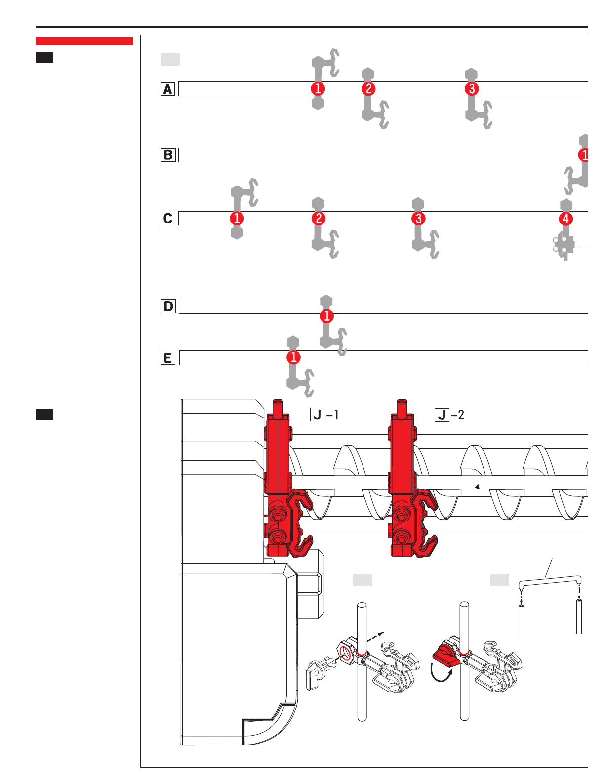
Installationofbaseplate,
shaftsandgearbox
Inserttheshafts(fg.07)intothe
baseplate(fg. 11, A-E)
Pleasenotethecorrectdirections
ofshafts
Attachthe3clipsatthebottom
ofthegearbox(seeredmarkings
infg.10)totheexactpre-defned
positionsofthebaseplate(fg.11)
Installationofshaftsand
arms
Attachthearmstotheshaft
(fg.07showsascaleof1:1)
Positionsofarms(fg.07):
Shaftsareshowninascale
of1:1.Attachthearmstothe
exactpre-defnedredpositions.
Pleasenotethecorrectorderand
directionsofarms
Inserttheshaftintoarmholder
B.Insertthearmwrenchintothe
armholderBandturnitby90
degreestofxthearm(fg.08)
Note: Tomodifytheangleofthe
arm, releasethefxationfrst
Attachtheconnectingpieces
[S3]totheshafts(fg. 09)
Pleasenotetheexactpre-defned
positionsoftheshaftsonthe
baseplate(fg. 11)
5
6
[S3] Connectingpiece
Note: Whenturningthearmwrench, makesurenot tochangetheright
positionof thearm
07
08 09

7
[G1] Gearbox
Back
Front
[G2] Gearboxsocket
Elevator
Positionforconnectingpiece[S3]
[S1] Shaft 300mm
[S1] Shaft 300mm
[S1] Shaft 300mm
[S2] Shaft 200mm
[S2] Shaft 200mm
Pleasenotethecorrect positions anddirections of arms (seeabove)
Seesaw(mountlefthandside) Seesaw(mountlefthandside)
Seesaw(mountrighthandside)
Back
Armposition Seesawposition
Down Up
Front
Connect withholes onbase
plate
Assembly of shafts, arms, gearbox and base plate
10 11

8
Rail connectionmarks
Releasearmtube[A3]beforemountingtherails
Lettersandnumbers(e.g. D-2)showthecorrect
positionsofshaftsandarmsdescribedonpage6-7
Loop(enlargedpicture)
Fromseesawexit(start) toelevatorentry:
Install 2x26cmrails (fg. 13-1)
Insert rail standattheendof
therail toensurebestseesaw
stability
Simplycut therails tothedesiredlength(seepage9: Rail joining)
Rail assemblysteps
Thisballrollercoasterprovides2elevatorexits(start)
and2elevatorentries(end).Pleasenotefg.12+13
andthepicturesonpage2+3duringassembly
Installrailstandstogetherwiththerails(page9)
Duetothelongdistance, theinstallationof this
sectionis dividedinto2 assemblysteps(please
refertofg. 12-1+12-2)
Fig.12-1and12-2showtheupperandlowertracklayout
Fig. 12-1: Fromelevator exit (start) totheloopentry
Fig. 12-2: Fromloopentrytolower elevator entry
Install 2 x245cmrails forthecompletedistance
infg. 12-1+12-2
Theenlargedpictureprovides furtherinformation
regardingloopinstallation
Fromelevatorexit (start) toseesawentry: Install 2x
105cmrails (fg. 13-2)
Fig.13-1and13-2showtheupperandlowertracklayout
Note:Fig.27onpage11providesfurtherassistanceif
thesteelballsdonotrunsmoothlyintotheelevator
7
12-1
12-2
13-1
14
13-2
Seesaw(enlargedview)
Correctseesawinstallation
Assembly of the rails
Don´tcut
Don´tcut

9
[R1] Rail
[R1] Rail
[R1] Rail
[A1] Arm
[R2] Rail joining
Insert rails intoarm
Userail stands likerailwayties
Install thearms inaninclinedpositiontoeachother tocreatesteepsections
Thedistancebetweenthearms should bebetween8 to 10cm.
Whenthedistanceis larger, rail stands [A6] havetobeinstalled
815
17
18
19
16
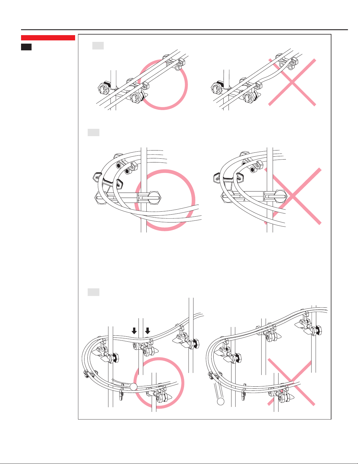
Installationoftherails
Inserttherails intothearms
(fg. 15+16)
Rail joining(fg. 17)
Adjust andconnecttherails.
Inserttherail joinings [R2] into
theholes atthecenterof the
rails (fg. 17)
Informationabout rail stands
(fg.18)
Thedistancebetweenthe
arms shouldbebetween8 to
10cmtoensurebeststability.
Whenthedistanceis larger,
rail stands [A6] havetobe
installed
Attachrail stands insteep
sections and elevatorentry/
exit points to ensurebest
stabilityof therails
Steepsections (fg.19)
Install thearms inaninclined
positiontoeachotherto
createsteepsections,so
that thesteel balls canrun
smoothly(fg.19)
Assembly of the rails
10
Assembly of the rails
Keeprails parallel
Curves need to beassembled ina certainangle
Adjust rails toreducespeed
20
21
22
8
Installationoftherails
Distancebetweenrails
(fg. 20)
Install therail standtokeep
rails parallel
Curves(fg. 21+22)
Curvesneedtobeassembled
inacertainangletoprevent
steel ballsfrommissingthe
turn(fg.21). Ifsteel balls
miss theturn,speedhastobe
reducedrightbeforethecurve
Adjust rails toreducespeed
of thesteel balls (f g. 22)
11
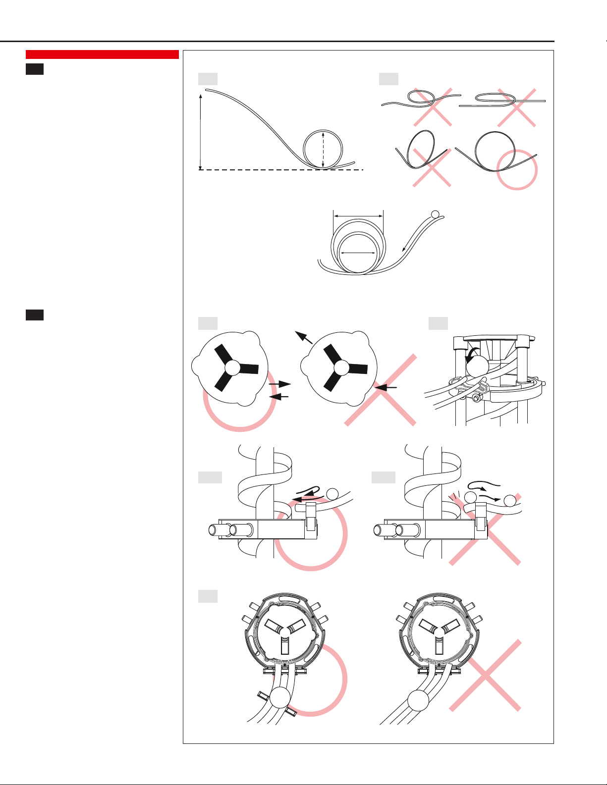
Installationofaloop
Ensurethesteelballsrunningsmoothly(fg. 23)
Thediameter of theouter loop shouldhavetwice
thediameter of theinner loop
Important informationfortheassemblyof loops
(fg. 24)
Rails haveto formacircle that remains inan
upright positionto ensurethesteel balls running
smoothly(fg. 24)
Whenmountingloops, thesecond loop has tobe
smaller thanthefrstlooptoensurethesteel balls
runningsmoothly
Installationofelevator(entry&exit)
Important information fortheassemblyof elevator
entryandexit (fg. 25)
Steel balls will not run correctlyif entryand exit
point inthesamedirection
Payattentionto aproperinstallationof theentry
andexit(fg. 26)
Install rails as closelyas possibletotheentryand
exit of theelevatorto ensurethesteel balls running
smoothly(fg. 26)
Payattentiontoacorrect angleoftherails whenthe
steel balls entertheelevator(fg. 27-1, 27-2, 28)
Makesurethesteel balls enter theelevatorslowly.
Otherwisetheywill rebound andfall off therails
(fg. 27-1)
Steel balls that enter theelevatormayrebound and
thownbackonto therails after hittingthehelix.
Payparticularattentionheretothecorrect seating
of therails. Otherwisethesteel balls will stopand
cannot re-enter theelevator(fg. 27-2)
At the entryall rails must beat right angles tothe
elevator(fg. 28)
Assembly of the rails
Loopdiameter
Height
Entry
Entry
Exit
Exit
Pleaserefer tothepictureabovefor thecorrect diameter of theinner loop
All rails must beat right angles to theelevator
23
25
28
26
27-1 27-2
24
9
10

12
Safety Instructions – Keep After Reading
General SafetyInstructions
This ball rollercoaster is NOTATOYandonlysuitablefor persons 14 years and older!
Warning: Readthemanual carefullybeforeusingtheball rollercoaster. Keepthe manual afterreading.
Always followexactlytherecommendations given in the instructions.
Errors and negligences inoperatingyour ball roller coaster can result ininjuries and damageto
property. As manufacturers andvendors haveno infuence onthe operation andmaintenance of your
ball roller coaster, webringthesehazards expresslyto your attention but denyall further liability.
Keepawayfromchildren. Theball rollercoastercontains small parts. Chokinghazard.
Warning: Sharp edges - watchyour fngers.
Warning: Do not drapetherail around your neck, as this couldresult insuffocation or injury.
Strangulationhazard.
Keep thepackagingfor futurereferenceas it contains important information.
SafetyInstructionsDuringOperation
Movingparts are aconstant sourceof injury. Never touch movingparts.
Keep hands, hair, loose clothingandfurther objects awayfrommovingparts.
Persons (includingchildren) with reducedphysical, sensoryor mental capabilities or lackof
experience arenot allowedto usethis ball roller coaster, unless theyaresupervisedbya person
responsiblefortheirsafetyandabletogiveprofessional advicehowtheproduct shouldbeused.
Do not bend the shafts and other parts to avoidinjuryand ensuresafe operation.
Keep fngers awayfromthemovingelevator to avoidinjury.
Onlyuseoriginal steel balls topreventdamageof theball roller coaster.
Caution: Violent jamming(stopping) duringoperationmaydamagethemotor. Do not cumber the
elevator.
Always storeandoperatetheball roller coaster at a safeplace.
Besure to checkbatteryregularlyto ensure aproper operationof theelevator.
Checkrails regularlyfor af rmseatingandadjust if necessary!
Protect theball roller coaster fromheatandsun.
Caution: Toprotect motorfromdamageandoverheating, do not operatethe ball rollercoasterformore
than 5hours at atime.
SafetyInstructionsForBatteries
Onlybatteries of thesameor equivalent typeas recommendedareto beused.
Exhausted batteries shouldbe removed fromtheball roller coaster.
Do not disposebatteries inf re – batteries will explodeor leak.
Batteryis to beinsertedwiththecorrect polarity.
Non-rechargeablebatteries arenot toberecharged.
Removebatteryif theball roller coaster is not to beusedfor anextended period of time.
Besure to checkbatteryregularlyto ensure aproper operationof theelevator.
Disposal Restrictions(WEEE)
Electrical and electronic equipment shouldbedisposedseparatelyfromthe householdwaste. Takeyour unwanted equipment to your local communitycollectionpoint. This requirement applies tomember
countries of theEuropeanUnionas well as other non-Europeancountries witha separatewastecollectionsystem. Never throwbatteries into normal householdwaste, but disposeof dischargedbatteries at the
collectionpointsprovidedforthat purpose(e.g. yourlocal toxicwastedisposal centre).
RecommendedAccessories: 1 xC/LR14 battery1.5V
Insertingthebattery: Usea Phillips screwdriverto openthe batterycompartment cover. Insert 1 xC/ LR14 batterywiththecorrect polarityandreplace the batterycompartment cover.
Distributedby:
SpaceRails LLC, 1910 West 1040 South, Salt Lake City, UT, 84104 - 801.486.6837 - www.spacerails.com
Table of contents
Other SpaceraiL Toy manuals


Popular Toy manuals by other brands


Fisher-Price
Fisher-Price M9972 instruction sheet

Eduard
Eduard Stryker Blast panels quick start guide

Rapido Trains
Rapido Trains british rail APT-E user manual

LEGO
LEGO 31034 CREATOR Assembly guide

REVELL
REVELL MESSERSCHMITT Me 410 B-6 / R-2 manual

Accucraft trains
Accucraft trains UNION PACIFIC 4-8-8-4 BIG BOY instruction manual