SpaceraiL LEVEL 1 - CLASSIC User manual

Spacerail ©2021
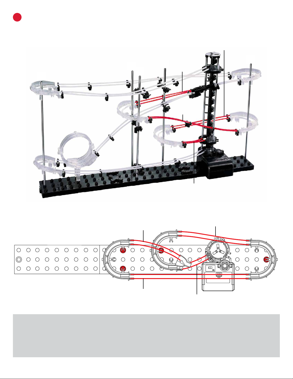
LEVEL 1 CLASSIC
PRODUCT AND CONSUMER WARNING
CHOCKING HAZARD: This product contains small parts and is not intended for children under 3.
• This product is intended for users over the age of 8.
• To avoid choking, keep small parts away from children.
• Use caution, this product contains parts with sharp edges.
• Only insert the steel marbles into the elevator to avoid damage to the product.
Spacerail ©2021
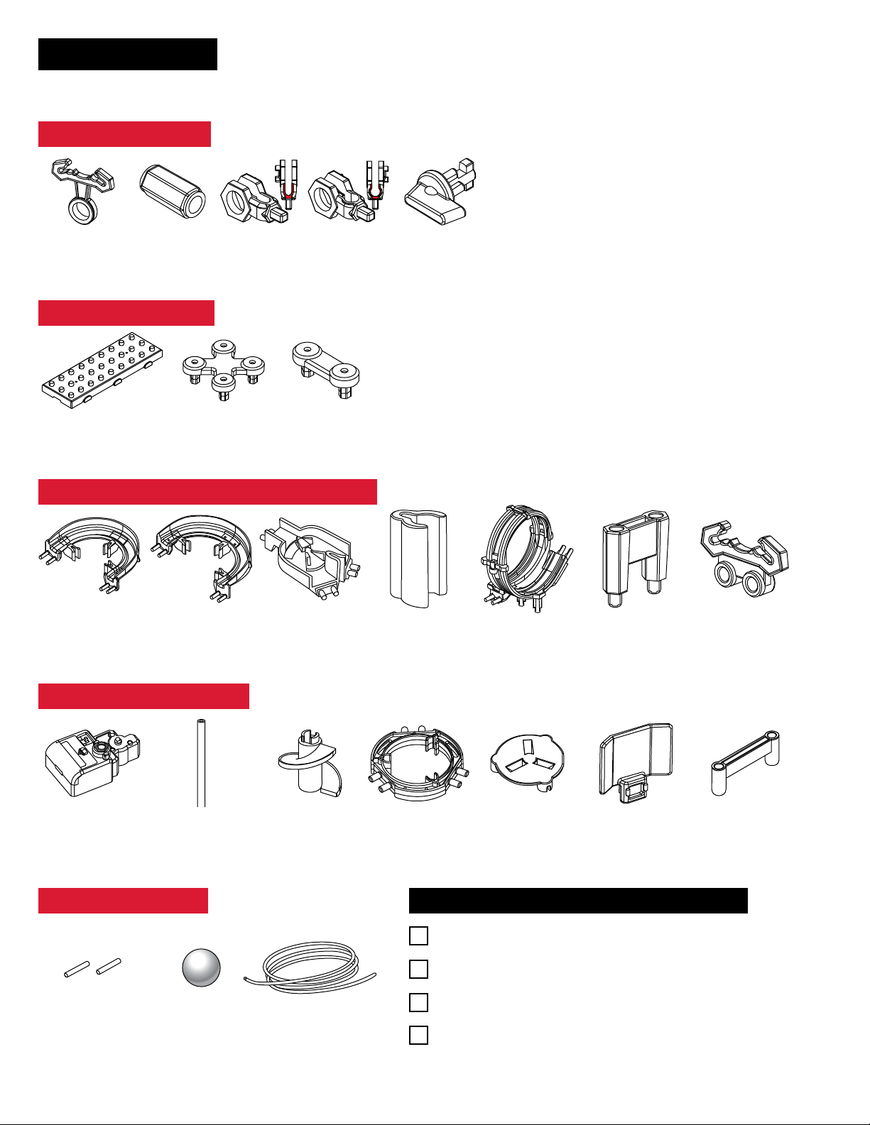
PARTS INCLUDED
Keep parts together to avoid misplacing them.
ARM COMPONENTS
Arm
5 PCS
Arm Sheath
5 PCS
Arm Holder A
5 PCS
Arm Holder B
5 PCS
Arm Wrench
5 PCS
LOOPS, TURNS, AND SPLIT COMPONENTS
Corner A
3 PCS
Corner B
3 PCS
Rail Splitter
1 PCS
Corner Stand
6 PCS
Loop
1 PCS
Loop Stand
1 PCS
Rail Clip
29 PCS
BASE COMPONENTS
Base Base Holder A Base Holder B
3 PCS 2 PCS 2 PCS
RAIL COMPONENTS
Rail Joining
2 PCS
Steel Marble
2 PCS
Rail
5000 mm
REQUIRED TOOLS & ITEMS NOT INCLUDED
Wire Cutters or Utility Scissors
Pen or Marker
1 battery - size AA
Ruler (in centimeters)
ELEVATOR COMPONENTS
Gear Box
1 PC
Shaft (300mm)
9 PCS
Elevator Helix
12 PCS
Elevator Ring
3 PCS
Elevator Cover
1 PC
Elevator Stand
3 PCS
Gear Box Stand
1 PC
Spacerail ©2021
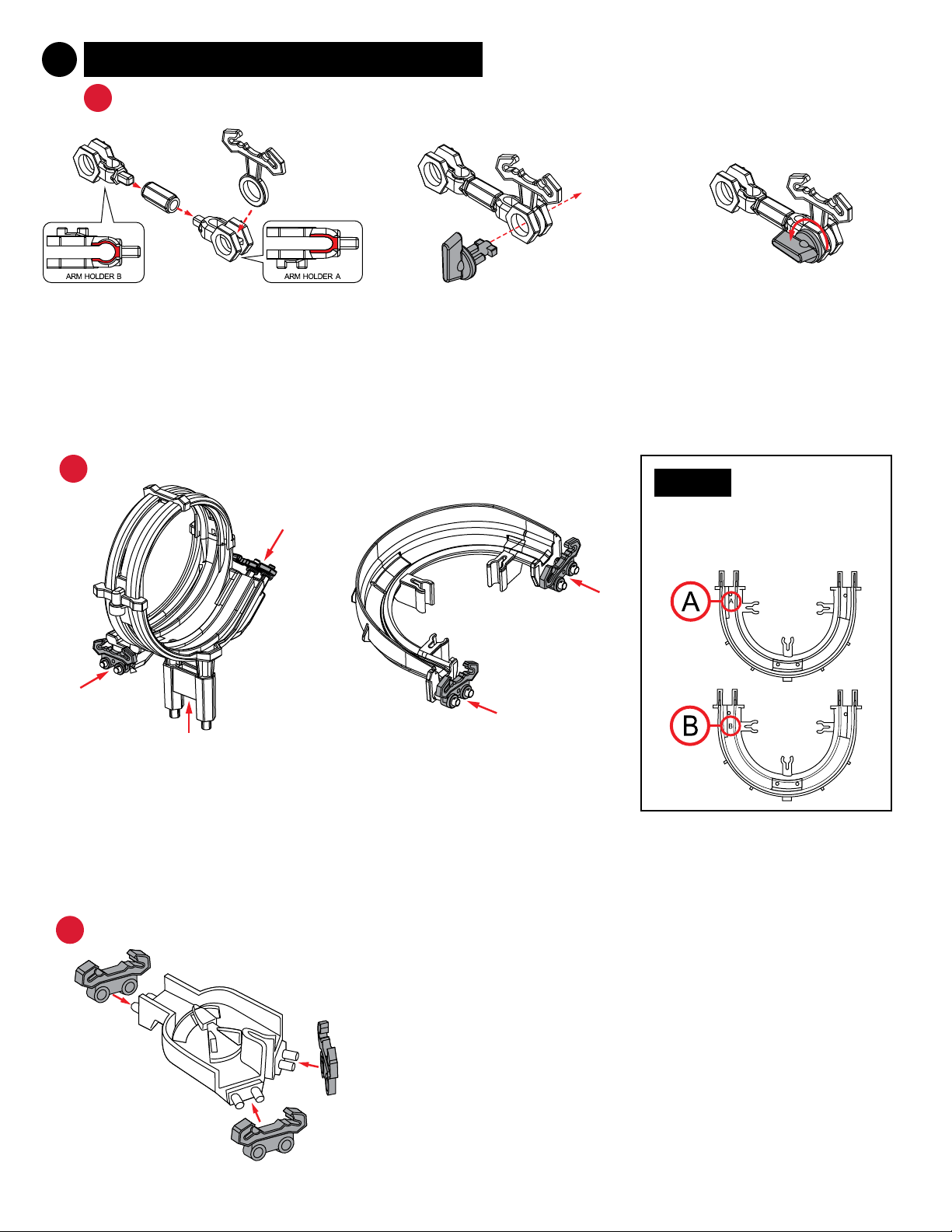
1PREPARE THE COASTER COMPONENTS
AARMS
Prepare the Loop: Find 2 Rail Clips
and attach them to both sides of
the Loop. Find the Loop Stand and
attach it to the bottom of the Loop.
Prepare the Turns: Find 2 Rail Clips
and attach them to both sides of
the Turn. Repeat this process with
all 6 Turns.
BLOOP & TURNS NOTE:
Corner A and Corner B are
distinguished by the letters on the
bottoms, as shown below.
CRAIL SPLITTER Prepare the Rail Splitter: Find the Rail
Splitter and 3 Rail Clips. Press the Rail Clips
on each of the Rail Splitter openings. Set
aside for coaster construction.
Step 1: Attach 1 Arm Holder A and
1 Arm Holder B with 1 Arm Sheath.
Insert 1 Arm into Arm Holder A.
Step 2: Align Arm in Arm Holder
with the Arm Wrench. Attach as
shown in step 3.
Step 3: Turn the Arm and Arm
Wrench counter-clockwise to lock
the arm in place.

Spacerail ©2021
Step 3: Once the
Corkscrew is built, attach
3 support shafts to the
Gear Box.
DELEVATOR
Step 2: Find the Elevator Helix
pieces and connect each
piece along the shaft.
NOTE:
There should not be any
space between the Gear
Box and the Helix. If the
Helix is not installed
correctly the Elevator will
not run.
Step 1: Find the Gear Box and
attach the shaft.
Step 6: Place the Elevator Cap onto
the top of the elevator assembly.
Step 7: Attach the 3 Elevator Guards
to each of the Elevator Rings.
Step 5: Place the 3 Elevator
Rings onto the Shafts.
NOTE:
The Steel Marble will fall
out of the elevator if it
enters too fast.
Step 4: Connect 1 Rail
Clip to each Elevator
Ring. Make sure
brackets on elevator
ring are right side up.
Spacerail ©2021
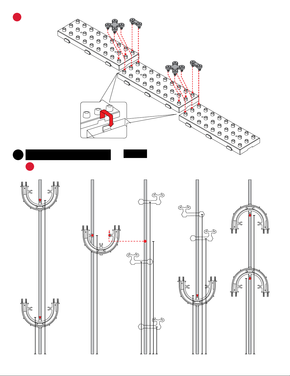
EBASE ASSEMBLY
2
1
2
Step 1: Locate all 3 Base blocks and
interlock together as shown below.
Step 2: Locate the Base Holder A and
Base Holder B and attach them to the
base blocks for a secure hold.
2CONSTRUCT THE COASTER
ABUILD THE COASTER SHAFTS
NOTE:
Illustration of Shafts are 1:2.3 or (approximately 43%) of scale.
A B C D E
63 mm
264 mm
204 mm
261 mm
194 mm
47 mm
159 mm
238 mm
129 mm
101 mm
240 mm
199 mm
Spacerail ©2021
LOOP
A
BC
DE
ELEVATOR
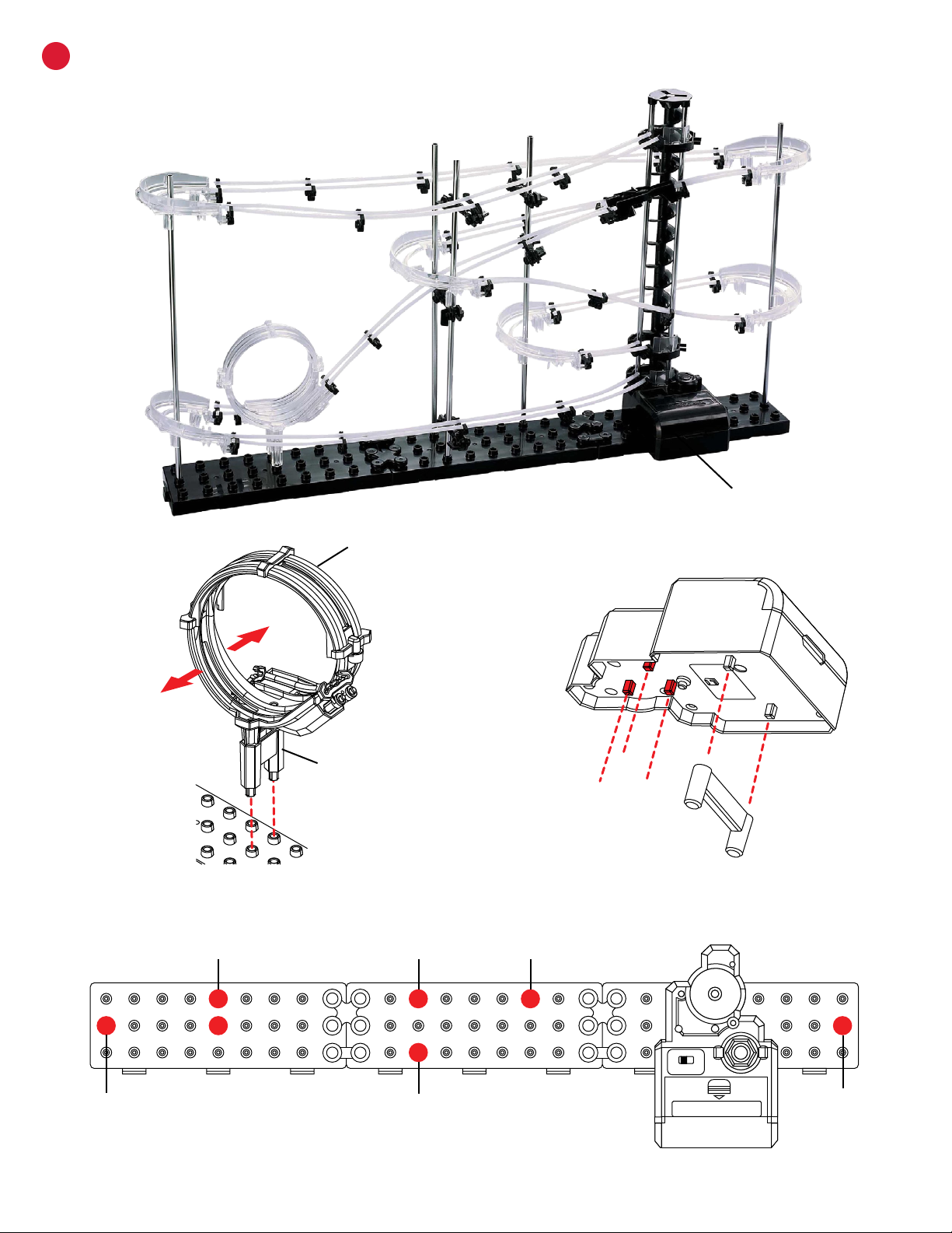
BINSTALL THE COASTER SHAFTS, LOOP AND ELEVATOR
Step 2: Attach Gear Box Stand to Gear Box.
BACK
FRONT
LOOP
LOOP STAND
Step 1: Attach Loop Stand to the bottom of the Loop.
PUSH
ONOFF
LOOP PART
SHAFT A
SHAFT B
SHAFT C
SHAFT D
SHAFT E
Step 3: Attach the Loop, Gear Box and all the Shafts to the Base.
Spacerail ©2021
CCUT THE RAIL TO SIZE
26mm
73mm
79mm
162mm
174mm
275mm
313mm
416mm
420mm
487mm
Step 1: Measure each section and mark the cutting point with a pen.
Step 2: Cut each section according to your measurement making sure to cut
at a 90 angle.
Tip: Cut longer rails slightly larger to be on the safe side. Longer rails can
always be cut a bit shorter. This will help you to avoid having to recut and not
having enough rail.
NOTE:
Illustration of rail lengths is 1:2.84 or
(approximately 35%) of scale.
Spacerail ©2021
Rail Joining for Custom Designs: To adjust your
designs with the rails, use the Rail Joinings to increase
the length of your rail sections.
Connecting Rails to Arms: To install the Rails, press
them into the Arm as shown. You should hear a click
sound when the Rail is locked in place.
Angling the Arms: Install the Arms at the angle of the
incline the Rails will travel along.
Railroad Stability: On the longer segments of Rail, attach
Rail Ties as needed to maintain stability along the track.
Smoothing the Elevator Exit: When installing the elevator
exit rails, pull the rails close to the Elevator Helix to ensure
the steel marble enters to the roller coaster easily.
Smooth Rails for Eicient Travel: Make sure the Rails
connect smoothly and are free of bumps or kinks.
Corner Stability: To provide extra stability on the
Corners, place Corner Stands directly below the Corners.
Rail and Corner Connections: Cut the rail at a 45°
angle where it meets a Corner. This will help smooth out
the transition as the steel marble ies around the track.
3CONSTRUCT THE ROLLER COASTER
ASSEMBLY TIPS & TRICKS
Spacerail ©2021
ACONNECT THE RAILS STEPS 13
Use the following illustrations and pictures as references for attaching the rails to the structure.
Step 1: Connect both A Rail sections between the Loop and the back bottom corner of Shaft A.
Step 2: Connect both G Rail Sections between the entrance of the loop and the front section of the Split.
Step 3: Connect both I Rail sections between the bottom entrance of the elevator and the bottom front corner of Shaft A.
A
BC
DE
STEP 1
(A Rail)
STEP 2
(G Rail)
STEP 3
(I Rail)
STEP 1
A Rail) STEP 2
(G Rail)
STEP 3
(I Rail)
A
Spacerail ©2021
BCONNECT THE RAILS STEPS 46
Use the following illustrations and pictures as references for attaching the rails to the structure.
Step 4: Connect both J Rail sections between the back top corner of shaft A and the back top corner of Shaft E.
Step 5: Connect Both H Rail sections between the exit of the Elevator and the front top corner of Shaft A.
Step 6: Connect both B Rail sections between the front top corner of Shaft E and the single side of the Split.
STEP 4
J Rail
STEP 5
H Rail STEP 6
B Rail
A
BC
DE
STEP 4
(J Rail)
STEP 5
(H Rail)
STEP 6
(B Rail)
EA
Spacerail ©2021
STEP 7
(D Rail)
STEP 8
(E Rail)
STEP 9
(F Rail) STEP 10
(C Rail)
CCONNECT THE RAILS STEPS 710
Use the following illustrations and pictures as references for attaching the rails to the structure.
Step 7: Connect both D Rail sections to the corner of Shaft B and the back section of the Split.
Step 8: Connect both E Rail sections between the back corner of Shaft D and the back bottom corner of Shaft E.
Step 9: Connect both F Rail sections between the front corner of Shaft C and the front bottom corner of Shaft E.
Step 10: Connect both C Rail sections between the front corner of Shaft D and the middle entrance of the Elevator.
A
BC
DE
STEP 7
(D Rail)
STEP 9
(F Rail)
STEP 10
(C Rail)
STEP 8
(E Rail)
E
B
C
D

Spacerail ©2021
Seaich Corporation
1910 West 1040 South
Salt Lake City, UT 84104
(833) 732-4242
Spacerails LLC
Spacerail © 2021
www.spacerails.com
Other manuals for LEVEL 1 - CLASSIC
1
Table of contents
Other SpaceraiL Toy manuals


Popular Toy manuals by other brands


Bell
Bell 206L Rotorcraft Flight Manual Supplement

AIRFIX
AIRFIX Avro Shackleton MR.2 A11004 Assembly instructions

Cen
Cen Grey thunder Assembly instructions

Opale-Paramodels
Opale-Paramodels Oxy 1.5 user guide

Mega Construx
Mega Construx POKEMON WONDER BUILDERS NIDORAN GMD23 manual

Hasbro
Hasbro Transformers Armada 7052 owner's manual

Hasbro
Hasbro Nerf N-Strike Big Bad Titan 11210 instruction manual

Faller
Faller VIADUCT SET, TWO-TRACK, CURVED manual

Mattel
Mattel Hot Wheels Daredevil Kurve W2107 quick start guide

marklin
marklin 39712 user manual

Design & Drill
Design & Drill Marble Maze instructions

Maxford USA
Maxford USA Neptune V2 instruction manual