spacewalker HOT-553 User manual

Spacewalker
HOT-553
Pentium^^'
processor
Based
PCI
main
board
User's
Manual
SPAC
E
W
A
LKER
FCC
Notice:
This
equipment
has
been
tested
and
found
to
comply
with
the
limits
fof
a
Class
B
digital
device,
pursuant
to
Part
IS
of
FCC
Rules.
These
limits
are
designed
to
provide
reasonable
protection
against
harmful
interference
in
a
residential
installation.
This
equipment
generates,
uses
and
can
radiate
radio
frequency
energy.
If
not
installed
and
used
properly,
in
strict
accordance
with
the
manufacturer's
instructions,
may
cause
harmful
interference
to
radio
communications.
Hoxvever,
there
is
no
guarantee
that
interference
will
not
occur
in
a
particular
installation.
If
this
equipment
does
cause
interference
to
radio
or
television
reception,
which
can
be
determined
by
turning
the
equipment
off
and
on,
the
user
is
encouraged
to
try
to
correct
the
interference
by
one
or
more
of
the
following
measures:
Reorient
or
relocate
the
receiving
antenna.
Increase
the
separation
between
the
equipment
and
receiver.
Connect
the
equipment
into
an
outlet
on
a
circuit
different
from
that
to
which
the
receiver
is
connected.
Consult
the
dealer
or
an
experienced
radio/television
technician
for
help
and
lor
additional
suggestions.
The
user
may
find
the
following
booklet
prepared
by
the
Federal
Communications
Commission
helpful
"Flow
to
Identify
and
Resolve
Radio-TV
Interference
Problems.'
This
booklet
is
available
from
the
U.S.
Government
Printing
Office.
Washington,
DC
20-102,
Stock
00-t-000-003-t5~l
FCC
Warning
The
user
is
cautioned
that
changes
or
modifications
not
expressly
approved
by
the
manufacturer
could
void
the
user's
authority
to
operate
this
equipment.
Note
;
In
order
for
an
instaffaiion
of
iliis
product
to
nrarntafr)
compliance
with
rfie
limits
(or
a
Class
B
device,
shielded
cables
and
power
cord
must
he
used.
NOTICE
Copyright
1996.
All
Right
Reserved
Manual
Ver
1.5
All
information,
documentation,
and
specifications
contained
in
this
marnial
are
subject
to
cfiange
vvitliorrt
prior
notification
by
the
manufacturer.
The
author
assumes
no
responsibility
for
.my
errors
or
omissions
which
may
appear
in
this
document
nor
does
it
make
a
commitment
to
update
the
information
contained
herein.
TRADEMARKS
Intel
is
a
registered
trademark
of
Intel
Corporation
Pendt/m"'
Processor
is
a
registered
trademark
of
Intel
Corporation
PC/AT
is
a
registered
trademark
of
Interrtational
Business
Machine
Corporation.
PS/2
is
a
registered
trademark
of
IBM
Corporation.
All
other
brand
and
product
rtames
referred
to
in
this
manual
are
trademarks
or
registered
trademarks
of
their
respective
holders.
M31
Table
of
Contents
Preface
3
Chapter
1
Introduction
4
Specification
4
Chapter
2
Jumper
setting
6
Jumpers
6
CPU
Clock
Speed
Selection
7
Onboard
Regulator
&
VRM
Selection
-
JP50,
JP51,
JP56,
JP57
9
Onboard
Voltage
Regulator
Output
Selection
-
JP5,
6,
7
9
Cache
Type
Selection
10
Pipeline
Burst
Type
Cache
Size
Selection
-
JP4,
JP64
11
Parallel
Port
DREQ
Selection
-
JP60,
JP61
12
Clear
Password
-
JP72
12
Flash
EPROM
jumper
-
jP9
1
3
Clear
CMOS-jPlI
13
Connectors
14
Chapter
3
Memory
Configuration
15
Chapter
4
Award
BIOS
Setup
16
The
Main
Menu
1
7
Standard
CMOS
Setup
19
BIOS
Features
Setup
21
Chipset
Features
Setup
23
Power
Management
Setup
26
PCI
Configuration
Setup
30
Password
Setting
32
12
User's
Manual

Preface
HOT-553
mainboard
is
a
highly
integrated
IBM
PC/AT
compatible
system
board.
The
design
will
accept
Intel
Pentium,
Cyrix
6x86
and
AMD5l<86
pro
cessors
and
also
features
high-performance
pipeline
burst
secondary
cache
memory
support
with
size
of
256KB
and
512KB.
The
memory
subsystem
is
designed
to
support
up
to
256
MB
of
EDO
RAM
or
standard
Fast
Page
DRAM
in
standard
72-pin
SIMM
socket.
A
type
7
Pentium
processor
socket
provides
access
to
future
processor
enhancements.
HOT-553
provides
a
new
level
of
I/O
integration.
Intel's
82430HX
PCiset
chip
set
provides
increased
integration
and
improved
performance
over
other
chip
set
designs.
The
82430HX
PCIset
chipset
provides
an
integrated
Bus
Mastering
IDE
controller
with
two
high
performance
IDE
interfaces
for
up
to
four
IDE
devices.
The
onboard
Super
I/O
controller
provides
the
standard
PC
I/O
functions;
floppy
interface,
two
FIFO
serial
ports,
an
IR
device
port
and
a
SPP/EPP/ECP
capable
parallel
port.
Up
to
four
PCI
local
bus
slots
provide
a
high
bandwidth
data
path
for
data-
movement
intensive
functions
such
as
graphics,
and
up
to
four
ISA
slots
com
plete
the
I/O
function.
The
HOT-553
provides
the
foundation
for
cost
effective,
high
performance,
highly
expandable
platforms,
which
deliver
the
latest
in
Pentium
processor
and
I/O
standard
User's
Manual
3

Specification
CPU
Function
□
Pentium
processors
:
75~200MHz
□
Cyrix
6x86
CPU
:
P90+~
PI
66
+
{VRM
is
required
for
Cyrix
6x86
CPU)
□
AMD
K5
CPU
;
PR75
-
PR150
□
Optional
VRM
socket
for
future
voltage
required
Chipset
□
Intel
PCISet
82439HX,
and
82371SB
Memory
□
Supports
two
banks
of
EDO
RAM
and
Fast
Page
DRAM
ranging
from
8MB
to
256MB
□
Supports
4MB, 8MB,
16MB,
32MB
and
64MB
72-pins
SIMMs
□
Supports
DRAM
Error
Checking
and
Correcting
(ECC)
Cache
Memory
□
Integrated
L2
write-back
cache
controller
-
256KB
or
512KB
Direct
Mapped
Pipeline
Burst
Cache
Power
Management
Function
□
Provides
four
power
management
modes
:
Full
on.
Doze,
Standby,
and
Suspend
□
Supports
Microsoft
APM
□
Provides
EPMI
(External
Power
Management
Interrupt)
pin
14
User's
Manual

Expansions
□
32-bit
PCI
bus
slot
x
4
□
16-bit
ISA
bus
slot
x
4
□
2-channel
PCI
IDE
port
-
Support
up
to
4
IDE
devices
-
PIO
Mode
4
transfers
up
to
16
MB/sec
-
Integrated
8
x
32-bit
buffer
for
PCI
IDE
burst
transfers
□
One
floppy
port
□
One
parallel
port
-
Supports
SPP
(PS/2
compatible
bidirectional
Parallel
Port),
EPP
(Extended
Parallel
Port),
and
ECP
(Extended
Capabilities
Port)
high
performance
parallel
port.
□
Two
serial
ports
-
Supports
16C550
compatible
UARTS.
-
Supports
serial
InfraRed
communication.
□
One
PS/2
mouse
port
□
USB
(Universal
Serial
Bus)
port
Board
Design
□
Dimension
22cm
x
28cm
User's
Manual
5
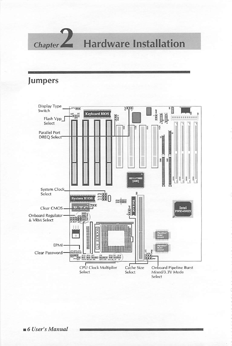
Jumpers
Hardware
Installation
Display
Type
Switch
Flash
Vpp
Parallel
Port
DREQ
Select
Keyboard
BIOS
System
Clock
Select
Clear
CMOS.
Onboard
Regulator-
&
VRM
Select
Clear
Password*
tl
!
ll.
CPU
Clock
Multiplier
Cache
Size
Onboard
Pipeline
Burst
Select
Select
Mixed/3.3V
Mode
Select
16
User's
Manual

CPU
Clock
Speed
Selection
HOT-553
mainboarcl
features
a
clock
generator
to
provide
adjustable
sys
tem
clock
frequency.
jP15,
jP16
and
jP79
are
all
2-pin
jumpers
which
determine
the
system
clock
frequency
from
40MHz
to
66MH2.
HOT-553
mainboard
also
provides
jP3
and
JP58
to
figure
up
CPtJ
core
clock
multiplier.
By
inserting
or
removing
jumper
caps
on
JP3
and
jP58
the
user
can
change
the
Host
Bus
Clock/CPU
Core
Clock
ratio
from
1
:
1.5
to
1
:
3.
CPU
Bus/Core
Ratio
System
Clock
CPU
Clock
Speed
)P16,
IP13,
)P79
tP3,
JP38
73
MH2
Pentium
Processor
30
MHz
90
MHz
Pentium
Processor
60
MHz
1M11
0
100
MHz
Pentium
Processor
66
MHz
iPT»r0
120
MHz
Pentium
Processor
60
MHz
123
MHz
Pentium
Processor
50
MHz
133
MHz
Pentium
Processor
66
MHz
150
MHz
Pentium
Processor
60
MHz
166
MHz
Pentium
Processor
66
MHz
180
MHz
Pentium
Processor
60
MHz
200
MHz
Pentium
Processor
66
MHz
User's
Manual
7

CPU
Clock
Speed
JP16JP15,
JP79
System
Clock
)P3,
IP58
CPU
Bus
/
Core
Ratio
80
MHz
Cyrix
6x86-
P90
+
IBBT
40
MHz
1
:
2
too
MHz
Cyrix
OxOO-PiaO-f-
50
MHz
(SDCOj
120
MHz
Cyrix
6x86-P150-t-
z'
m
•
m
60
MHz
UHSJltU
1
:
2
133
MHz
Cyrix
6x86-P166
+
••
66
MHz
CPU
Clock
Speed
JP16,JP15,|P79
System
Clock
JP3,JP58
CPU
Bus/Core
Ratio
75
MHz
AMDK5
PR75
JPU
JPIS
50
MHz
in
iP>i
rgTirnti
90
MHz
AMD
K5
PR90
ipvi
m
m
60
MHz
JP)
JP5»
[0](0)
too
MHz
AMD
K5
-
PR100
••
66
MHz
^■3)[0)
90
MHz
AMDK5-PR120
1—1
IPI3
tP7»
#0
60
MHz
1
:1.5
100
MHz
AMD
K5-
PR133
••
66
MHz
iP3
)P<»
IISSS
120
MHz
AMDK5-PR150
JPI6
1—1
IP7V
%
<1
60
MHz
18
User's
Manual
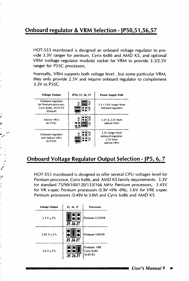
Onboard
regulator
&
VRM
Selection
-
JP50;51^56^57
HOT-553
mainboard
is
designed
an
onboard
voltage
regulator
to
pro
vide
3.3V
ranger
for
pentium,
Cyrix
6x86
and
AMD
K5,
and
optional
VRM
(voltage
regulator
module)
socket
for
VRM
to
provide
3.3/2.5V
ranger
for
P55C
processors.
Normally,
VRM
supports
both
voltage
level
,
but
some
particular
VRM,
they
only
provide
2.5V
and
require
onboard
regulator
to
complement
3.3V
to
P55C.
Voltage
Output
IPSO,
51,56,
57
Power
Supply
Path
Onboard
regulator
for
Pentium
processor.
Cyrix
6x86,
AMD
K5
(Default)
3.3
-
3.6V
ranger
from
onboard
regulator
Addon
VRM
forP55C
alUi
3.3V
&
2.5V
from
addon
VRM
Onboard
regulator
and
Addon
VRM
forP55C
sUl!
ibbI*b|-
tFst
3.3V
ranger
from
onboard
regulator,
2.5V
from
addon
VRiM
Onboard
Voltage
Regulator
Output
Selection
-
JP5^
6,
7
HOT-553
mainboard
is
designed
to
offer
several
CPU
voltages
level
for
Pentium
processor,
Cyrix
6x86,
and
AMD
K5
family
requirements.
3.3V
for
standard
75/90/100/120/133/166
MHz
Pentium
processors,
3.45V
for
VR
s-spec
Pentium
processors
(3.3V
+5%
-0%),
3.6V
for
VRE
s-spec
Pentium
processors
(3.45V
to
3.6V)
and
Cyrix
6x86
and
AMD
K5.
Voltage
Output
3.3
V±
3%
I
Pentium
SIDA'R
J5
J6J7
3.45
V±5%
J5
J6J7
Pentium
VRA'RI
JS
J6J7
Pentium
VRE
Cyrix
6x86
AMD
K5
User's
Manual
9

Cache
Type
Selection
HOT-553
mainboard
support
onboard
pipeline
burst
cache
SRAM,
and
pipeline
burst
cache
module.
Onboard
pipeline
burst
cache
RAM
A
factory
option
on
HOT-553
mainboard
is
an
integrated
256KB
external
cache
implemented
with
two
32K
x
32
pipeline
burst
SRAM
devices
soldered
to
the
mainboard.
A
32KB
x
8
external
Tag
SRAM
is
required.
Pipeline
Burst
cache
module
If
the
HOT-553
is
ordered
with
no
cache
installed,
the
cache
can
be
added
later
in
a
field
upgrade
by
installing
a
256KB
pipeline
burst
cache
module
into
the
CELP
socket.
If
factory
option
on
HOT-553
mainboard
integrate
256KB
pipeline
burst
cache
installed
already,
the
cache
size
can
be
field
upgrade
to
512KB
by
installing
a
256KB
pipeline
burst
cache
module
into
the
CELP
socket.
(please
refer
to
section
of
"Pipeline
Burst
Type
Cache
Size
Selection")
110
User's
Manual

HOT-553
mainboard
supports
256KB
or
512KB
pipeline
burst
cache
size.
If
the
HOT-553
is
ordered
with
no
cache
installed,
the
cache
can
be
field
upgraded
by
installing
a
first
256KB
pipeline
burst
cache
module
into
the
CELP
socket.
If
factory
option
on
HOT-553
mainboard
integrate
256KB
pipeline
burst
cache
onboard
mounted
already,
the
cache
size
can
be
field
upgraded
to
512KB
by
installing
a
secondary
256KB
pipeline
burst
cache
module
into
the
CELP
socket.
256KB
Cache
Memory
1
as
On
mainboard
integrate
256KB
pipeline
burst
cache
mounted,
or
a
first
256KB
pipeline
burst
cache
module
in
the
CELP
socket.
512KB
Cache
Memory
On
mainboard
integrate
256KB
pipeline
burst
cache
mounted
and
a
secondary
256KB
pipeline
burst
cache
module
in
the
CELP
socket.
Note
:
There
are
some
technical
difference
between
first
256KB
pipeline
burst
cache
module
and
secondary
one,
if
512KB
cache
memory
are
required,
please
contact
your
supplier
for
help.
User's
Manual
11

Parallel
Port
DREQ
Selection
-
JP60,
JP61
HOT-553
mainboard
onboard
parallel
port
supports
ECP
mode
(Extended
Capabilities
Port),
and
provide
two
available
DMA
Request
lines
DREQl
and
DREQ3
for
it.
When
an
ECP
mode
device
is
in
use,
the
user
may
assign
DREQl
or
DREQ3
for
parallel
port.
If
SPP/EPP
mode
is
selected,
the
user
may
ignore
those
jumpers.
["■]
Jumper
JP59
factory
default
on
ra
Parallel
Port
JP60,
JP61
DMA
Selection
Parallel
Port
ECP
Mode
DMA
Request
1
151
MM
(default)
Parallel
Port
ECP
Mode
ii1
DMA
Request
3
HI
Clear
Password
-
JP72
Allows
system
password
to
be
cleared
by
shorting
jumper
jP72
and
turning
the
system
on,
"Password
is
cleared
by
jumper,
(JCP)!"
message
will
shown
up
on
power-on
screen.
The
system
should
then
be
turned
off
and
the
jumper
JP72
should
be
returned
to
OPEN
to
restore
normal
operation.
The
procedure
should
only
be
done
if
the
user
password
has
been
forgotten.
(This
function
may
not
available
when
Cyrix
6x86
CPU
is
in
use)
112
User's
Manual
/
,r
Flash
EPROM
Jumper
-
JP9
HOT-553
mainboard
supports
two
types
of
flash
EPROM,
5
volt
and
12
volt.
By
setting
up
jumper
jP9,
you
can
update
both
types
of
flash
EPROM
with
new
system
BIOS
files
as
they
come
available.
JP9
open
for
5V,
Pin
2-3
close
for
12V.
BIOS
UPGRADES
Flash
memory
makes
distributing
BIOS
upgrades
easy.
A
new
version
of
/
the
BIOS
can
be
installed
from
a
diskette.
The
flash
upgrade
utility,
Awdflash.exe,
has
two
notice
for
BIOS
upgrades.
Flash
utility
can't
work
under
protected/virtual
mode.
Memory
manager
like
QEMM.386,
EMM386
should
not
be
loaded,
(or
Simply
bypass
all
config.sys
and
autoexec.bat
on
system
boot
up.
Flash
utility
supports
both
5V
and
12V
Flash
EEPROM.
Clear
CMOS-jPII
HOT-553
mainboard
supports
jumper
|P11
for
discharge
mainboard's
CMOS
memory.
The
CMOS
memory
retains
the
system
configuration
information
in
the
component
of
R.T.C.
You
should
short
this
jumper
for
a
moment
when
you
wish
to
clear
CMOS
memory,
and
then
make
sure
open
this
jumper
for
normal
opera
tion
to
retain
your
new
CMOS
data.
Note:
Clear
CMOS
&
R.T.C
function
available
only
when
"DS12887A
"
or
"DS128887"
are
in
use.
There
are
different
ways
to
discharge
CMOS
memory
between
"DS12887A"
and
"DS12B887".
DS12887A
-
Turn
off
power,
close
jumper
JP11
for
2
to
3
seconds
then
release
and
CMOS
will
be
discharged.
DS12B887
-
Close
jumper
JP11,
turn
on
power
durning
2
to
3
seconds
then
release
jP11
and
turn
off
power,
CMOS
will
be
discharged.
User's
Manual
13

Connectors
Connectors
ITEM
FUNCTION
IDEl
On-board
PCI
Primary
IDE
Connector
IDE2
On-board
PCI
Secondary
IDE
Connector
JI
On-board
Floppy
Controller
Connector
PI
On-board
Parallel
Port
Connector
Sl
On-board
Serial
port-1
Connector
52
On-board
Serial
Port-2
Connector
IP52
On-board
PS/2
Mouse
Port
Connector
|P8
Power
LED
and
Keylock
Connector
JP7
PC
Speaker
Connector
IPI2
Hardware
Reset
Switch
Connector
JPI4
Turbo
LED
Connector
JP72
Clear
BIOS
Password
JP74
Green
LED
JP19
EPMI
Connector
)P20
On-board
Enhanced
IDE
R/W
LED
Connector
JP80,JP81
Universal
Serial
Bus
(USB)
Connectors
JP63
IR
Communication
Port
Connector
1P71
Display
type
(Color/Mono)
Switcher
USB
Connectors
Pin-out
3
2
T3
t
i
c
>
Q
a
a
JP63
-
Infra-Red
2
3
4
VCC
VCC
IROA
CNO
IRIA
PS/2
Mouse
Connector
HOT-553
mainboard
provides
two
type
of
PS/2
style
mouse
connectors,
type
A
and
type
B,
the
right
table
shows
the
pinout
connection
for
each
type.
Type
A
T^peB
PIN
IVPf
A
TY«
B
1
f
mfiiy
CkKk
2
Cround
rm|4y
3
Cliick
Grtiur«l
4
Ground
VCC
5
VCC
OjU
b
Imfity
Im|4y
7
I
m|<y
8
Impry
9
I)jU
10
f
mfily
14
User's
Manual
Chapter
<A
Memoc^^anfiguration
J
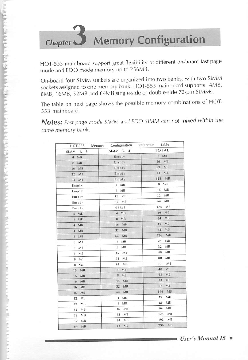
HOT-553
mainboard
support
great
flexibility
of
different
on-board
fast
page
mode
and
EDO
mode
memory
up
to
256MB.
On-board
four
SIMM
sockets
are
organized
into
two
banks,
with
two
SIMM
sockets
assigned
to
one
memory
bank.
HOT-553
mainboard
supports
4MB,
8MB,
16MB,
32MB
and
64MB
single-side
or
double-side
72-pin
SIMMs.
The
table
on
next
page
shows
the
possible
memory
combinations
of
HOT-
553
mainboard.
Notes:
Fast
page
mode
SIMM
and
EDO
SIMM
can
not
mixed
within
the
same
memory
bank.
HOT-553
Memory
Cott
figuration
Reference
Table
SIMM
1,
1
SIMM
3,
4
TOTAL
4
MB
Empty
8
MB
8
MB
Empty
16
MB
16
MB
Empty
32
MB
32
MB
Empty
64
MB
64
MB
Empty
128
MB
Empty
4
MB
8
MB
Empty
B
MB
16
MB
Empty
16
MB
32
MB
Empty
32
MB
64
MB
Empty
6
4.MB
128
MB
4
MB
4
MB
16
MB
4
MB
8
MB
24
MB
4
MB
16
MB
40
MB
4
MB
32
MB
?2
MB
4
MB
64
MB
136
MB
8
MB
4
MB
24
MB
8
MB
8
MB
32
MB
8
MB
16
MB
46
MB
8
MB
32
MB
80
MB
8
MB
64
MB
144
MB
16
MB
4
MB
40
MB
16
MB
8
MB
48
MB
16
MB
16
MB
64
MB
16
MB
32
MB
96
MB
16
MB
64
MB
160
MB
32
MB
4
MB
72
MB
•32
.MB
8
MB
80
MB
32
MB
16
.MB
96
MB
32
MB
32
MB
128
MB
32
MB
64
.MB
192
MB
64
MB
64
MB
256
MB
User's
Manual
15

4
Chapter^
Award
BIOS
Setup
HOT-553's
BIOS
ROM
has
a
built-in
Setup
program
that
allows
users
to
modify
the
basic
system
configuration.
This
type
of
information
is
stored
in
battery-backed
RAM
so
that
it
retains
the
Setup
information
when
the
power
is
turned
off.
Bntering
Setup
Power
on
the
computer
and
press
<
Del
>
immediately
will
allow
you
to
enter
Setup.
The
other
way
to
enter
Setup
is
to
power
on
the
com
puter,
when
the
below
message
appear
briefly
at
the
bottom
of
the
screen
during
the
POST
(Power
On
Self
Test),
press
<Del>
key
or
simultaneously
press
<Ctrl>,<Alt>,
and
<Esc>
keys.
TO
ENTER
SETUP
BEFORE
BOOT
PRESS
CTRL-ALT-ESC
OR
DEL
KEY
If
the
message
disappears
before
you
respond
and
you
still
wish
to
enter
Setup,
restart
the
system
to
try
again
by
turning
it
OFF
the
ON
or
pressing
the
"RESET"
button
on
the
system
case.
You
may
also
restart
by
simultaneously
press
<Ctrl>,
<Alt>,
and
<Delete>
keys.
If
you
do
not
press
the
keys
at
the
correct
time
and
the
system
does
not
boot,
an
error
message
will
be
displayed
and
you
will
again
be
asked
to,
PRESS
F1
TO
CONTINUE,
CTRL-ALT-ESC
OR
DEL
TO
ENTER
SETUP
\16
User's
Manual
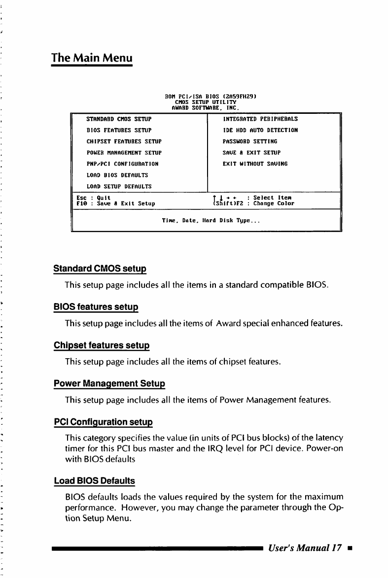
The
Main
Menu
Ron
pcixisn
BIOS
(2A59FH29)
CHOS
SETUP
UTILITY
OHflBD
SOFTWARE.
INC.
STANDARD
CMOS
SETUP
INTEGRATED
PERIPHERALS
BIOS
FEATURES
SETUP
IDE
HDD
AUTO
DETECTION
CHIPSET
FEATURES
SETUP
PASSWORD
SETTING
POWER
HANAGEHENT
SETUP
SAVE
a
EXIT
SETUP
PNP^PCI
CONFIGURATION
EXIT
WITHOUT
SAUING
LOAD
BIOS
DEFAULTS
LOAD
SETUP
DEFAULTS
Esc
:
Quit
FIO
:
Saue
8
Exit
Setup
t
i
:
Select
Itepi
(Shift)F2
:
Change
Color
TiPie,
Date.
Hard
Dish
Type...
Standard
CMOS
setup
This
setup
page
includes
all
the
items
in
a
standard
compatible
BIOS.
BIOS
features
setup
This
setup
page
includes
all
the
items
of
Award
special
enhanced
features.
Chipset
features
setup
This
setup
page
includes
all
the
items
of
chipset
features.
Power
Management
Setup
This
setup
page
includes
all
the
items
of
Power
Management
features.
PCI
Configuration
setup
This
category
specifies
the
value
(in
units
of
PCI
bus
blocks)
of
the
latency
timer
for
this
PCI
bus
master
and
the
IRQ
level
for
PCI
device.
Power-on
with
BIOS
defaults
Load
BIOS
Defaults
BIOS
defaults
loads
the
values
required
by
the
system
for
the
maximum
performance.
However,
you
may
change
the
parameter
through
the
Op-
lion
Setup
Menu.
User's
Manual
17
Load
Setup
Defaults
Setup
defaults
loads
the
values
required
by
the
system
for
the
minimum
performance.
However,
you
may
change
the
parameter
through
the
Setup
Menu.
IDE
HDD
auto
detection
Automatically
configure
IDE
hard
disk
drive
parameters.
Password
setting
Change,
set,
or
disable
password.
It
allows
you
to
limit
access
to
the
system
and
Setup,
or
just
to
Setup.
Save
&
Exit
setup
Save
CMOS
value
change
to
CMOS
and
exit
setup
Exit
without
saving
Abandon
all
CMOS
value
changes
and
exit
setup.
118
User's
Manual
standard
CMOS
Setup
BOH
PC
ISA
BIOS
(2A5SCH2A)
STANDABD
CMOS
SETUP
AUABD
SOFTUABE.
INC.
Date
(pin:dd:yy)
Tine
(hh:nn:ss)
HABD
DISKS
Sat.
17
:
Bug
12
1995
18
:
33
TYPE
SIZE
CVLS
HEAD
PBECONP
LANDZ
SECTOB
KODE
Prinary
Master
:
Auto
Prlmry
Slaue
:
Auto
Secondary
Master
:
Auto
Secondary
Slave
:
Auto
0
0
0 0 0
AUTO
0
0 0 0 0
AUTO
0
0
0
0 0
AUTO
0
0 0 0 0
AUTO
Drive
A
Drive
B
Uldeo
Halt
On
1.44M.
3.5
In.
None
EGA^UOA
All
Errors
Base
Menory:
640K
Extended
Memry:
15360K
Other
Memry:
384K
Total
Memry:
16384K
ESC
F1
Quit
Help
T
I
(Shi
Select
Iten
Change
Color
PU^PD/*/-
:
Modify
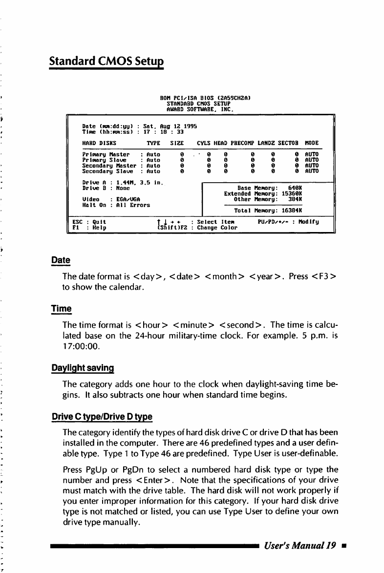
Date
The
(date
format
is
<day>,
<date>
<
month
>
<year>.
Press
<F3>
to
show
the
calendar.
Time
The
time
format
is
<
hour
><
minute
>
<
second
>.
The
time
is
calcu
lated
base
on
the
24-hour
military-time
clock.
For
example.
5
p.m.
is
17:00:00.
Daylight
saving
The
category
adds
one
hour
to
the
clock
when
daylight-saving
time
be
gins.
It
also
subtracts
one
hour
when
standard
time
begins.
Drive
C
type/Drive
D
type
The
category
identify
the
types
of
hard
disk
drive
C
or
drive
D
that
has
been
installed
in
the
computer.
There
are
46
predefined
types
and
a
user
defin
able
type.
Type
1
to
Type
46
are
predefined.
Type
User
is
user-definable.
Press
PgUp
or
PgDn
to
select
a
numbered
hard
disk
type
or
type
the
number
and
press
<
Enter
>.
Note
that
the
specifications
of
your
drive
must
match
with
the
drive
table.
The
hard
disk
will
not
work
properly
if
you
enter
improper
information
for
this
category.
If
your
hard
disk
drive
type
is
not
matched
or
listed,
you
can
use
Type
User
to
define
your
own
drive
type
manually.
User's
Manual
19
Table of contents
Other spacewalker Motherboard manuals


