020–0065 • 040326–B
Secure Embedded Web Application Kit
Getting Started
Application Kit Contents
•Dynamic C CD-ROM, with complete product documentation on disk.
•3 CD-ROMs with related Dynamic C modules and sample programs: FAT File System, RabbitWeb, and
Secure Sockets Layer (SSL).
•RCM3700 module.
•Prototyping Board.
•AC adapter, 12 V DC, 1 A (included only with Development Kits sold for the North American market).
A header plug leading to bare leads is provided to allow overseas users to connect their own power
supply with a DC output of 7.5–30 V.)
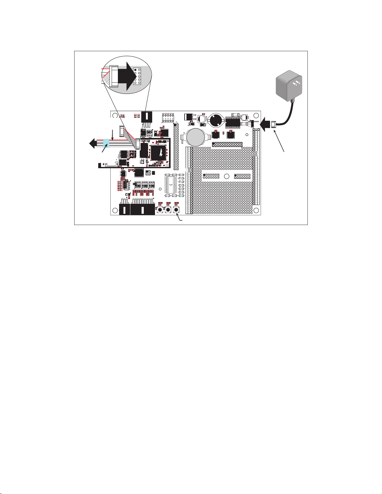
•Programming cable with 10-pin header and DE9 con-
nections, and integrated level-matching circuitry.
•Cable kits to access RS-485 and analog input connec-
tors on Prototyping Board.
•Getting Started instructions.
•Accessory parts for use on the Prototyping Board.
•Rabbit 3000 Processor Easy Reference poster.
•Registration card.
Starting Dynamic C
Once the RCM3700 is connected as described in the preceding pages, start Dynamic C by double-clicking
on the Dynamic C icon or by double-clicking on dcrabXXXX.exe in the Dynamic C root directory,
where XXXX are version-specific characters.
Dynamic C uses the serial port specified during installation.
Run a Sample Program
Use the File menu to open the sample program PONG.C, which is in the Dynamic C SAMPLES folder.
Press function key F9 to compile and run the program. The STDIO window will open on your PC and will
display a small square bouncing around in a box.
Where Do I Go From Here?
If the sample program ran fine, you are now ready to go on to other sample programs and to develop your
own applications. The source code for the sample programs is provided to allow you to modify them for
your own use. The RCM3700 User's Manual also provides complete hardware reference information
and describes the software function calls for the RCM3700, the Prototyping Board, and the optional LCD/
keypad module.
If Dynamic C appears to compile the BIOS successfully, but you then receive a communication error mes-
sage when you compile and load the sample program, it is possible that your PC cannot handle the higher
program-loading baud rate. Try changing the maximum download rate to a slower baud rate as follows.
•Locate the Serial Options dialog in the Dynamic C Options > Project Options > Communica-
tions menu. Select a slower Max download baud rate.
If a program compiles and loads, but then loses target communication before you can begin debugging, it is
possible that your PC cannot handle the default debugging baud rate. Try lowering the debugging baud rate
as follows.
•Locate the Serial Options dialog in the Dynamic C Options > Project Options > Communica-
tions menu. Choose a lower debug baud rate.
If there are any other problems:
•Check that the RCM3700 is powered correctly — the power LED above the RESET button on the
Prototyping Board should be lit.
•Check to make sure you are using the PROG connector, not the DIAG connector, on the programming
cable.
•Check both ends of the programming cable to ensure that they are firmly plugged into the PC and the
programming port on the RCM3700.
•Ensure that the RCM3700 module is firmly and correctly installed in its connectors on the Prototyping
Board.
•Select a different COM port within Dynamic C. From the Options menu, select Project Options,
then select Communications. Select another COM port from the list, then click OK. Press <Ctrl-Y>
to force Dynamic C to recompile the BIOS. If Dynamic C still reports it is unable to locate the target sys-
tem, repeat the above steps until you locate the active COM port.
•Check the Z-World/Rabbit Semiconductor Technical Bulletin Board at www.zworld.com/support/bb/.
•Use the Technical Support e-mail form at www.zworld.com/support/support_submit.html.
NOTE: If you purchased your RCM3600 through a distributor or through a Z-World or Rabbit
Semiconductor partner, contact the distributor or partner first for technical support.
Installing Dynamic C
Insert the CD from the Application Kit in
your PC’s CD-ROM drive. If the installation
does not auto-start, run the setup.exe
program in the root directory of the
Dynamic C CD. Install any Dynamic C
modules after you install Dynamic C.