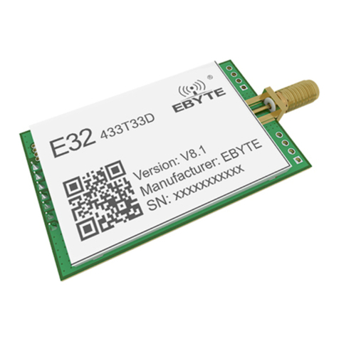
Sparklan WPEQ-405AX User manual

Wireless Module
All Rights Reserved. SparkLAN may make changes to specification and descriptions at any time without prior notice.
WPEQ-405AX
Ver.0.94
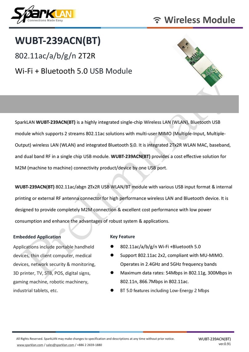
WPEQ-405AX
WiFi 6 (802.11ax) 4x4 MU-MIMO
5GHz Single Band Mini PCIe Module
The first WiFi-6 (802.11ax) Qualcomm based AP solution on module formfactor from SparkLAN.
WPEQ-405AX, is based on QCN9074 chipset solution. This is a true enterprise based wireless module that
powers 4T4R (4x4) MU-MIMO, in 5Ghz Single band mode, hitting a theoretical speed of up to 4.8Gbps with
160MHz support.
Unlike typical Qualcomm reference design around QCN9074 (PN02.1), WPEQ-405AX shrink the traditional
50mmx50mm M.2 E-Key design to a more popular Mini PCIe Full size formfactor of just 50mm x 30mm, run
at 3.3V voltage. Provides a greater versatility to use on more common seen design.
WPEQ-405AX performs both AP and STA functionality with 4 spatial streams, although recommended more
for hardware AP applications as it supports 4096-QAM, OFDMA technology, makes it perfect for heavy
lifting applications such as Enterprise grade AP, UTM, public & transportation Hotspot, and other industrial
capable Access Points.
802.11ax with MU-MIMO 4x4 Solution
Embedded Application
Applications include Multimedia
Router and AP solution., etc.
Key Feature
•5GHz, 4x4 MU-MIMO OFDMA Technology,
up to 4804Mbps physical data rate
•Single Band 5GHz 4x4 Wi-Fi 6 (802.11ax)
•4 spatial streams (4SS)
•Perfect for AP solutions
•Support standard full size Mini PCIe module

Wireless Module
All Rights Reserved. SparkLAN may make changes to specification and descriptions at any time without prior notice.
WPEQ-405AX
Ver.0.94
Specification
Standards
IEEE 802.11ax/ac/a/n (4T4R)
Chipset Qualcomm Atheros QCN9074
Data Rate
802.11a: 54Mbps
802.11n: MCS0~15
802.11ac: MCS0~9
802.11ax: HE0~11
Operating Frequency
IEEE 802.11ax/ac/a/n
ISM Band: 5.150GHz~5.850GHz
*Subject to local regulations
Interface
WLAN: PCIe
Form Factor Mini PCIe
Antenna
4 x IPEX MHF1 connectors
Modulation
Wi-Fi :
802.11n: OFDM (BPSK, QPSK, 16-QAM, 64-QAM)
802.11a: OFDM (BPSK, QPSK, 16-QAM, 64-QAM)
802.11ac: OFDM (BPSK, QPSK, 16-QAM, 64-QAM, 256-QAM)
802.11ax: OFDMA (BPSK, QPSK, DBPSK, DQPSK,16-QAM, 64-QAM, 256-QAM,
1024-QAM, 4096-QAM )
Power Consumption
TX mode: 1954mA(Max.)
RX mode: 819mA(Max.)
Operating Voltage
DC 3.3V
Operating Temperature Range -20°C ~ +70°C (TBD)
Storage Temperature Range
-20°C ~ +90°C
Humidity
(Non-Condensing)
5%~90% (Operating)
5%~90% (Storing)
Dimension L x W x H (in mm)
50.80mm(±0.3mm) x 29.85mm(±0.3mm) x 9.30mm(±0.3mm) (TBD)
Weight (g) TBD g
Driver Support
Linux (Open Source)
Security 64/128-bits WEP, WPA, WPA2, 802.1x

Wireless Module
All Rights Reserved. SparkLAN may make changes to specification and descriptions at any time without prior notice.
WPEQ-405AX
Ver.0.94
Pin Assignment (TBD)
The following section illustrate signal pin-outs for the module connector.
TOP
Pin# Pin Name Type Description
1 WAKE# -
Open Drain active Low signal. When the add-in card
supports wakeup, this signal is used by the add-in card to
request that the system return from a sleep/suspended
state to service a function initiated wake event.
When the add-in card supports the OBFF mechanism,
this signal is used by the system to indicate OBFF or CPU
Active State transitions.
3 NC -No connect
5 NC -No connect
7 PCIE_CLKREQ_L OD PCIe clock request
9 GND G Ground connections
11 REFCLK-
I PCIe differential clock input- Negative
13 REFCLK+
I PCIe differential clock input- Positive
15 GND G Ground connections
17 NC -No connect
19 NC -No connect
21 GND G Ground connections
23 PCIE_TDN O PCIe Transmit data-Negative
25 PCIE_TDP O PCIe Transmit data-Positive
27 GND G Ground connections
29 GND G Ground connections
31 PCIE_RDN I PCIe receive data-Negative
33 PCIE_RDP I PCIe receive data-Positive
35 GND G Ground connections
37 GND G Ground connections
39 VDD_3V3_SIP P VDD system power supply input
41 VDD_3V3_SIP P VDD system power supply input
43 GND G Ground connections
45 PCIE_L1_TXM -WLAN PCIe L1 transmit output differential signals
47 PCIE_L1_TXP -WLAN PCIe L1 transmit output differential signals
49 PCIE_L1_RXM -WLAN PCIe L1 receive input differential signals
51 PCIE_L1_RXP -WLAN PCIe L1 receive input differential signals

Wireless Module
All Rights Reserved. SparkLAN may make changes to specification and descriptions at any time without prior notice.
WPEQ-405AX
Ver.0.94
BOTTOM
Pin# Pin Name Type Description
2 VDD_3V3 P VDD system power supply input
4 GND G Ground connections
6 NC -No connect
8 NC -No connect
10 NC -No connect
12 NC -No connect
14 NC -No connect
16 NC -No connect
18 GND G Ground connections
20 W_DISABLE1#(NA) I
22 PCIE_PERST_L I PCIe host indication to reset the device. Active low.
24 NC -No connect
26 GND G Ground connections
28 NC -No connect
30 NC -No connect
32 NC -No connect
34 GND G Ground connections
36 USB_D- I/O USB serial differential data Negative
38 USB_D+ I/O USB serial differential data Positive
40 GND G Ground connections
42 LED_WWAN#
O
44 LED_WLAN#
O
46 NC -No connect
48 NC -No connect
50 GND G Ground connections
52 VDD_3V3_SIP P VDD system power supply input
Note: power (P), ground (G), open-drain (OD), input (I), output (O), Do Not Connect (DNC), No Connection (NC)

Installation
Connect the Module to the PCIe slot of the computer.
Install Wi-Fi driver driver.
After the Wi-Fi Driver is installed , click the Network icon on the Windows, then
search the network , and connect the Wireless Network you want.
Federal Communication Commission Interference Statement:
This equipment has been tested and found to comply with the limits for a Class B digital
device, pursuant to part 15 of the FCC Rules. These limits are designed to provide
reasonable protection against harmful interference in a residential installation. This
equipment generates, usesand can radiate radio frequency energy and, ifnot installed
and used in accordance with the instructions, may cause harmful interference to radio
communications. However, there is no guarantee that interference will not occurin a
particular installation. Ifthis equipment does cause harmful interference to radio or
television reception, which can be determined by turning the equipment offand on, the
user isencouraged to try to correct the interference by one or more of the following
measures:
—Reorient or relocate the receiving antenna.
—Increase the separation between the equipment and receiver.
—Connect the equipment into an outlet on a circuit different from that to which the
receiver isconnected.
—Consult the dealer oran experienced radio/TV technician for help.
Any changes or modifications not expressly approved by the party responsible for
compliance could void your authority to operate the equipment.
RF exposure statements
This Transmitter must not be co‐located or operating in conjunction with any other
antenna or transmitter.
This equipment complies with FCC RF radiation exposure limits setforth for an
uncontrolled environment. This equipment should be installed and operated with a
minimum distance of 26centimeters between the radiator and your body or nearby
persons.
CFR 47 SUBPART E (15.407) has been investigated. Itisapplicable to the modular
transmitter.

The devices must be installed and used in strict accordance with the manufacturer's
instructions as described in the user documentation that comes with the product.
This radio transmitter RYK-WPEQ405AX has been approved by Federal
Communications Commission to operate with the antenna types listed below, with the
maximum permissible gain indicated. Antenna types not included in this list that have a
gain greater than the maximum gain indicated for any type listed are strictly prohibited
for use with this device.
Unique antenna connector (RP-SMA) must be used on the Part 15 authorized
transmitters used in the host product.
Antenna Type
Antenna Model
Maximum Gain (dBi)
Remark
2.4 GHz 5GHz
Dipole AD-103AG 2.02 dBi 2.03 dBi
Dipole AD-302N 3.14 dBi 2.74 dBi
Dipole AD-303N 3.14 dBi 3.24 dBi
Length of Antenna cable:150mm Connector type of Antenna cable: I-PEX/MHF4 to RP-
SMA(F)
If the FCC identification number is not visible when the module is installed inside
another device, then the outside of the device into which the module is installed must
also display a label referring to the enclosed module. This exterior label can use
wording such as the following: “Contains Transmitter Module FCC ID: RYK-
WPEQ405AX” Or “Contains FCC ID: RYK-WPEQ405AX”
The modular transmitter is only FCC authorized for the specific rule parts (i.e., FCC
transmitter rules) listed on the grant, and the host product manufacturer is responsible
for compliance to any other FCC rules that apply to the host not covered by the modular
transmitter grant of certification. The final host product still requires Part 15 Subpart B
compliance testing with the modular transmitter installed.

Industry Canada statement:
This device complies with Industry Canada license-exempt RSSs. Operation is subject
to the following two conditions:
1) This device may not cause interference, and
2) This device must accept any interference, including interference that may cause
undesired operation of the device.
Le présent appareil est conforme aux CNR d’Industrie Canada applicables aux
appareils radio exempts de licence. L’exploitation est autorisée aux deux conditions
suivantes :
1) l’appareil ne doit pas produire de brouillage;
2) l’utilisateur de l’appareil doit accepter tout brouillage radioélectrique subi, meme si le
brouillage est susceptible d’en compromettre le fonctionnement.
Caution:
1) The device for operation in the band 5150–5250 MHz is only for indoor use to reduce
the potential for harmful interference to co-channel mobile satellite systems;
2) For devices with detachable antenna(s), the maximum antenna gain permitted for
devices in the bands 5250-5350 MHz and 5470-5725 MHz shall be such that the
equipment still complies with the e.i.r.p. limit;
3) For devices with detachable antenna(s), the maximum antenna gain permitted for
devices in the band 5725-5850 MHz shall be such that the equipment still complies with
the e.i.r.p. limits specified for point-to-point and non-point-to-point operation as
appropriate; and
Avertissement:
1) Le dispositif fonctionnant dans la bande 5150-5250 MHz est réservé uniquement
pour une utilisation à l’intérieur afin de réduire les risques de brouillage préjudiciable
aux systèmes de satellites mobiles utilisant les mêmes canaux;
2) Le gain maximal d’antenne permis pour les dispositifs avec antenne(s) amovible(s)
utilisant les bandes 5250-5350 MHz et 5470-5725 MHz doit se conformer à la imitation
P.I.R.E.;
3) Le gain maximal d’antenne permis pour les dispositifs avec antenne(s) amovible(s)
utilisant la bande 5725-5850 MHz doit se conformer à la limitation P.I.R.E spécifiée pour
l’exploitation point à point et non point à point, selon le cas.

Radiation Exposure Statement:
This equipment complies with IC radiation exposure limits setforth for an uncontrolled
environment. This equipment should be installed and operated with minimum distance
26cm between the radiator & your body.
Déclaration d’exposition aux radiations:
Cet équipement est conforme aux limites d’exposition aux rayonnements ICétablies
pour un environnement non contrôlé. Cet équipement doit être installé et utilisé avec un
minimum de 26cm de distance entre la source de rayonnement et votre corps.
This radio transmitter (IC: 6158A-WPEQ405AX has been approved by Industry Canada
to operate with the antenna types listed below with the maximum permissible gain
indicated. Antenna types not included in this list, having a gain greater than the
maximum gain indicated for that type, are strictly prohibited for use with this device.
Le présent émetteur radio (IC: 6158A-WPEQ405AX a été approuvé par Industrie
Canada pour fonctionner avecles types d'antenne énumérés cidessous et ayant un
gain admissible maximal. Les types d'antenne non inclus dans cette liste, et dont le gain
est supérieur au gain maximal indiqué, sont strictement interdits pour l'exploitation de
l'émetteur.
Antenna Type
Antenna Model
Maximum Gain (dBi)
Remark
2.4 GHz 5GHz
Dipole AD-103AG 2.02 dBi 2.03 dBi
Dipole AD-302N 3.14 dBi 2.73 dBi
Dipole AD-303N 3.14 dBi 3.24 dBi
If the ISED certification number is not visible when the module is installed inside another
device, then the outside of the device into which the module is installed must also
display a label referring to the enclosed module. This exterior label can use wording
such as the following: “Contains IC: 6158A-WPEQ405AX”.
Si le numéro de certification ISDE n'est pas visible lorsque le module est installé à
l'intérieur d'un autre appareil, alors l'extérieur de l'appareil dans lequel le module est
installé doit également afficher une étiquette faisant référence au module inclus. Cette
étiquette extérieure peut utiliser un libellé comme celui-ci: “ Contient IC: 6158A-
WPEQ405AX“.
Plaque signalétique du produit final:

Le produit final doit être étiqueté dans un endroit visible avecl'inscription suivante:
"Contient des IC: 6158A-WPEQ405AX ".
Manual Information To the End User:
The OEM integrator has to be aware not to provide information to the end user
regarding how to install or remove this RF module in the user’s manual of the end
product which integrates this module.
The end user manual shall include all required regulatory information/warning as show
in this manual.
Manuel d'information à l'utilisateur final
L'intégrateur OEM doitêtre conscient de ne pas fournir des informations à l'utilisateur
final quant à la façon d'installer ou de supprimer ce module RF dans le manuel de
l'utilisateur du produit final quiintègre ce module. Le manuel de l'utilisateur final doit
inclure toutes les informations réglementaires requises et
avertissements comme indiqué dans ce manue
Must use the device only in host devices that meet the FCC/ISED RF exposure
category of mobile, which means the device is installed and used at distances of at least
26cm from persons.
The end user manual shall include FCC Part 15 /ISED RSS GEN compliance
statements related to the transmitter as show in this manual.
Host manufacturer isresponsible for compliance of the host system with module
installed with all other applicable requirements for the system such as Part 15 B, ICES
003.
Host manufacturer isstrongly recommended to confirm compliance with FCC/ISED
requirements for the transmitter when the module is installed in the host.
Must have on the host device a label showing Contains FCC ID: 6158A-WPEQ405AX,
Contains IC: 6158A-WPEQ405AX
The use condition limitations extend to professional users, then instructions must state
that this information also extends to the host manufacturer’s instruction manual.
If the end product will involve the Multiple simultaneously transmitting condition or
different operational conditions for a stand-alone modular transmitter in a host, host
manufacturer have to consult with module manufacturer for the installation method in
end system.
l'hôte doit utiliser l'instrument uniquement dans des dispositifs qui répondent à la fcc /
(catégorie d'exposition rf mobile, ce qui signifie le dispositif est installé et utilisé à une

distance d'au moins 26cm de personnes.
le manuel de l'utilisateur final doit inclure la partie 15 / (fac rss gen déclarations de
conformité relatives àl'émetteur que de montrer dans ce manuel.
le fabricant est responsable de la conformité de l'hôte, lesystème d'accueil avecle
module installé avec toutes les autres exigences applicables du système comme la
partie 15 b, ices - 003. accueillir le fabricant est fortement recommandé de confirmer la
conformité avec les exigences de la fcc / (émetteur lorsque le module est installé dans
l'hôte.
le dispositif d'accueil doivent avoir une étiquette indiquant contient FCC ID: RYK-
WPEQ405AX, contient IC : 6158A-WPEQ405AX
Table of contents
Other Sparklan Wireless Module manuals


