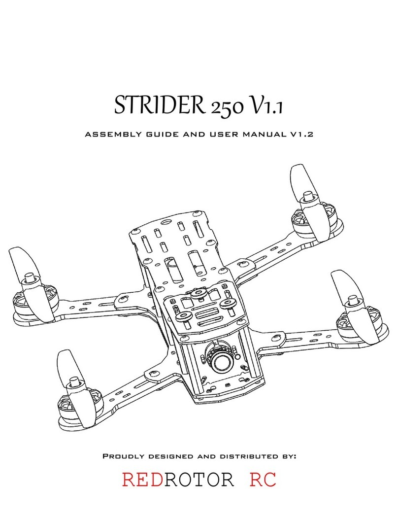
Sparrow R4 User manual

sparrowquad.com
©2015 QuadQuestions LLC All Rights Reserved. Patent Pending.
1

sparrowquad.com
©2015 QuadQuestions LLC All Rights Reserved. Patent Pending.
2
Print on 8.5”x11” paper for proper scale.

sparrowquad.com
Introduction
Thank you for purchasing the Sparrow R4 Quadcopter and welcome to the Team Sparrow
Family!
This manual details how to physically assemble the frame. There is a diverse array of electrical
components that can be used with quadcopter frames, an example set is included in this
document and further examples are available on the quadquestions.com website.
There is also a growing array of upgrades and customizations, both functional and cosmetic
available from quadquestions.com
If you have any questions, please feel free to contact us.
A great amount of thought and care has been put into this quadcopter frame and we want you to
be successful in your FPV adventure.
We have included ample hardware to build the kit and you will find that we have given you extra
screws and nylon standoffs. These will come in handy throughout your Sparrow’s life, so make
sure to put the extra hardware into your crash kit for when the time comes.
We have also designed and continue to design many gadgets for the frame such as Sparrow
Claws (nylon landing gear), angled camera mounts, Sparrow Armor (titanium screw sets) and
more. Please visit QuadQuestions.com for more information
Warning- Carbon fiber is a conductive material and care
should be taken when using electronics with carbon fiber.
Carbon can cause shorts and catch fire if directly
shorted between power and ground.
We would like for you to take caution when building our kit. One of the main problems that we
see people have when building quadcopters is using motor mounting screws that are too long.
Warning- If your motor screws are too long you will short the motor to
ground through the frame and this will cause many problems for you.
Please make sure that you're using motor screws that are the correct length for your motor.
©2015 QuadQuestions LLC All Rights Reserved. Patent Pending.
3

sparrowquad.com
In addition to the hardware scale part quantities, you should also have included with
your kit:
1 Sparrow main plate (A)
1 Sparrow Power distribution Board (B)
1 Velcro strap (C)
2x Multicolor LED strips (D)
1x XT-60 Battery Connector (D)
1x top 2mm front plate (E)
1x top 2mm rear plate (F)
1x Battery plate (G)
1x 2mm Allen Key (H)
1x 3D printed FPV camera holder with aluminum insert (J)
4x Sparrow 270mm Arms (K)
1x FPV Hanger Plate (L)
1X sparrow Bumper plate (M)
3x Anti-vibration mounts with screws and locknuts (N)
©2015 QuadQuestions LLC All Rights Reserved. Patent Pending.
4

sparrowquad.com
Tools Required
Soldering Iron
6 in one screwdriver
Solder
Heat Shrink
Additional Parts recommended to complete build
BASIC COMPONENTS
4X motors such as Cobra 2000KV for 6” configurations, or 2300KV for 5” configurations
4X Escs Such as DYS BLheli Sn20s or Kiss 18a ESCs (or Lumenier 20A with BEC included)
1X flight controller, Such as a Naze32,Openpilot CC3D, SP3Racing, or other
1X BEC for powering your Flight Controller (can be taken care of with OSDOGE See below)
Propellers CW/CCW -We recommend high quality propellers such as HQ Prop or ATG.
Radio and receiver such as An FrSky Taranis and a D4R-II
Appropriate to battery supply AWG wire for XT-60 connector, along with other wire for
providing power to additional components.
FPV GEAR:
LC Power Filter (already included if using an OSDoge)
Video transmitter Such as a TS58500 (please be aware of national laws)
Sony Superhad CCD camera or other CCD camera
OSD such as an OSDoge or Minim OSD
Cloverleaf antenna
To simplify your FPV setup, we recommend a DTF UHF OSDoge board when using a Naze32
flight controller. As well as an OSD, this board will provide clean (filtered) power for the Video
transmitter and 12V or 5V cameras.as well as powering the Naze32..
YOU SHOULD PLAN A FEW HOURS FOR YOUR BUILD, A QUAD BUILD CAN TAKE QUITE A BIT OF
TIME TO GET RIGHT, SO TRY NOT TO RUSH THROUGH IT!
©2015 QuadQuestions LLC All Rights Reserved. Patent Pending.
5

sparrowquad.com
Step 1- Solder your power wires.
It is at this time that we recommend that you solder the LED wires, and XT-60 Connector to your
PDB. It is good practice to dry fit the XT-60 connector to the frame and measure the wire
lengths needed for this. We have found that 60mm (about 2.5”) is a good starting length. We
recommend you check and double check your wiring orientation (positive to positive, negative to
negative as getting this wrong can result in the failure of multiple electronic components.
©2015 QuadQuestions LLC All Rights Reserved. Patent Pending.
6

sparrowquad.com
Step 2- Solder your ESCs
Solder ESCs to the Power distribution board. The Sparrow PDB is arranged in such a way that
your ESCs will be installed with two facing upright and two facing down. This has been done to
space out the positive and negative leads as much as possible to avoid shorting, Again it is
important to get the orientation correct.
Step 3- install the PDB Standoffs
Install the Standoffs onto the PDB (B) as shown in the diagram below.
©2015 QuadQuestions LLC All Rights Reserved. Patent Pending.
7

sparrowquad.com
Step 4 - Prepare Main Plate.
To prepare the main plate (A) install the (D) spacers and Flight Controller mounting hardware
(not shown or included) as pictured in the diagram below. There are mounting holes in the main
plate to position a 36x36mm Flight Controller such as the Naze32 as close to the center of
gravity as possible.
©2015 QuadQuestions LLC All Rights Reserved. Patent Pending.
8

sparrowquad.com
Step 5- Attach PDB plate to main plate.
Having set up the PDB and prepared the main plate, the next step is to attach the two together.
Carbon fiber is a conductive material, please take care to ensure that the ESCs and
connections to them do not make an electrical contact with the main board. Typically ESCs are
appropriately insulated however if this has been removed, for example to solder motor wires
directly to the ESCs, please ensure appropriate insulation (heat shrink or electrical tape) has
been re applied. It is also good practice to prevent undue stress on solder joints to secure the
ESCs with tape, zip ties or glue..
©2015 QuadQuestions LLC All Rights Reserved. Patent Pending.
9

sparrowquad.com
Step 6- Prepare front and rear top plates
The next step is to install all hardware into the front (E) and rear(F) top plates. At this time you
should also install your flight controller (the flight controller should have already been prepared
in accordance with the manufacturers’ manual (all soldering completed) and other components
to the main frame. Be sure at this point to install the aluminum anodized washers under the
inner bolts as shown in the diagram below:"
©2015 QuadQuestions LLC All Rights Reserved. Patent Pending.
10

sparrowquad.com
Step 7- Install the FPV Dampener Assembly
©2015 QuadQuestions LLC All Rights Reserved. Patent Pending.
11

sparrowquad.com
Step 8- Install the arms
The next step is to install the arms (K) on to the front plate (E). Install the arms onto the top
plates of the quad, and then install the completed upper front and rear assemblies onto the
bottom plate as shown in the diagram below:
The arms only go on one way, please pay attention to the detail of their orientation. If the arms
are difficult to fit onto the bolts, then you can try to loosen the 3 screws that go through each
arm to make their installation a bit easier.
©2015 QuadQuestions LLC All Rights Reserved. Patent Pending.
12

sparrowquad.com
Step 9- Install the top assemblies onto the main plate.
Fit the front and rear top plate assemblies onto the main plate. It is at this time that you will also
install the landing gear and arm-bolt locknuts as shown in the diagram below:
©2015 QuadQuestions LLC All Rights Reserved. Patent Pending.
13

sparrowquad.com
Step 10- Fasten the front and rear top plates
Complete the attachment of the front and rear top plates to the main frame. "
©2015 QuadQuestions LLC All Rights Reserved. Patent Pending.
14

sparrowquad.com
Step 11- Assemble the camera assembly.
The FPV camera is not included. The Sparrow Racing Quadcopter can use both 36mm board
mount cameras and cased cameras such as the Runcam Sky. The diagram below shows the
mounting procedure for a 36mm board camera. The 2.5x16mm screws and the 3x8mm
standoffs for board mounted cameras are optional and not included in the kit.
©2015 QuadQuestions LLC All Rights Reserved. Patent Pending.
15

sparrowquad.com
Step 12- Attach the FPV camera assembly to the
vibration dampener plate.
©2015 QuadQuestions LLC All Rights Reserved. Patent Pending.
16

sparrowquad.com
Step 13- Attach the FPV Camera assembly to the main
frame.
©2015 QuadQuestions LLC All Rights Reserved. Patent Pending.
17

sparrowquad.com
Step 14- Install the Front Bumper Plate
The next step is to complete the electronics installation such as wiring up the flight controller,
hooking up the FPV gear, installing the radio receiver, routing the antennas and Installing the
motors. (This is also the ideal point to check motor rotation is in the correct direction and
calibrate the ESCs – please refer to the documentation for the relevant flight controller
firmware). After which the front bumper plate (M) can be installed as shown in the diagram
below:
©2015 QuadQuestions LLC All Rights Reserved. Patent Pending.
18

sparrowquad.com
Step 15- Install the battery plate
The final step is to install the battery plate (G) this should be done once all of the electrical items
have been installed and tested (the configuration of some combination of electrical components
requires extensive physical access, please refer to the documentation of the components being
used).
Either the 3x10 standoffs provided can be used as shown, or if a larger stack is in use, 3x18can
be used instead.
©2015 QuadQuestions LLC All Rights Reserved. Patent Pending.
19

sparrowquad.com
Please have fun and be safe with your new Sparrow Racing Quad. As
always, if you have any questions, please reach out to us at
www.sparrowquad.com.
A special thanks to Cheredanine for helping to edit this manual. Written
By Anthony Jacobs-Cad images and assembly procedure by Dick Lam
©2015 QuadQuestions LLC All Rights Reserved. Patent Pending.
20
Table of contents
