LotusRC T580 User manual

T580 Basic Quadcopter LOTUS
1
RC
Manual Edition: 2011-March-12
Safety Precautions
1. Please read this manual before building and flying the aircraft.
2. The product is a radio-controlled model with exposed rotating blades.
Therefore it poses some safety risk.
3. Do take the necessary steps to prevent being hit by the rotating blades or
motors and avoid personal injury.
4. If you have never built a quadcopter before, we advise you to seek help and
guidance from someone who has.
Disclaimer
1. Do not use this product for illegal reasons or purposes.
2. LotusRC and our dealers bare no responsibility on how this product is utilized.
3. This model contains a large number of sophisticated components and
electronics, which may fail over time. LotusRC and our dealers assume no
responsibility to any losses, be it direct and indirect as a consequence to this
failure.
Agreement
Upon purchasing this product, you automatically accept to the above
agreement.

T580 Basic Quadcopter LOTUS
2
RC
Table of Contents
T580 BASIC COMPONENTS AND FUNCTION .........3
TOOLS NEEDED TO COMPLETE THE T580........................................................................................ 3
PARTS LIST..................................................................................................................................... 4
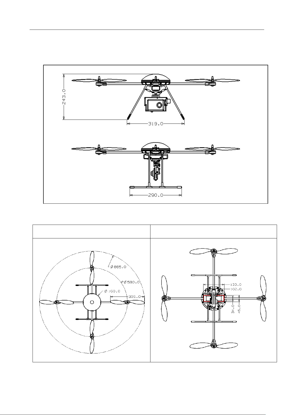
AIRCRAFT DIMENSIONS (MM):....................................................................................................... 5
TECHNICAL PARAMETERS............................................................................................................... 6
T580AIRCRAFT COMPONENTS ...................................................................................................... 7
ELECTRONIC COMPONENTS ........................................................................................................... 8
PROCESSOR SOFTWARE.................................................................................................................. 8
AIRCRAFTASSEMBLY .................................................................................................................... 9
Main body.................................................................................................................................. 9
Remote Control Receiver Installation..................................................................................... 12
RADIO SETTINGS .................................................................................................................. 13
Powering Up for the First Time............................................................................................... 13
Initialization Beep Tones:........................................................................................................ 13
FIRST FLIGHT........................................................................................................................ 14
WARNING: PLEASEREAD BEFOREYOUR FIRST TESTFLIGHT ............................. 14
4. Control Direction.............................................................................................................. 14
BUILIT IN SAFETYFEATURES.............................................................................................. 17
1. Loss of RC Signal............................................................................................................. 17
2. Start-Up throttle protection:............................................................................................. 17
3. In-flight Protection during RC Signal lost ....................................................................... 17
4. Low battery protection ..................................................................................................... 17
5. Beeping Tone Summary:................................................................................................... 18
FEEDBACK ................................................................................................................................... 18
UPGRADE PARTS ..................................................................................................................... 19
PAN TILT ZOOM (PTZ) CAMERA MOUNT........................................................................... 19

T580 Basic Quadcopter LOTUS
3
RC
T580 Basic Components and Function
a) The T580 Quadcopter is a high precision four-rotor aircraft designed for
stable recreational flight and aerial photography.
b) The aircraft arrives fully built and flight tested. However, to ship it to you
the landing gear and propellers had to be dismantled - a 15 minute
reassembly job.
c) To get this unit flying, you will need your RC Gear (at least 4 Channel
Receiver) and 3s1p LiPo battery (2200mAh).
d) Lift is achieved using four high efficiency 12-inch propellers with direct drive
low KV brushless motor. Maximum lifting efficiency of 12g per Watt.
e) The T580 utilizes a high-performance MEMS sensor for 6 DOF stabilization
with low drift. Altitude hold is achieved via an integrated barometric
sensor.
f) The T580 can take off and land vertically, hover, altitude hold, fly left, right,
forward and back with ease.
g) Upgrading this basic quadcopter for aerial photography is easy via
plug-n-play camera mount and stabilization system. Check our website to
purchase these upgrade.
Tools needed to complete the T580
•2mm Hex Screwdriver
•Loctite
•5 mm socket Hex Screwdriver or a good Plier
•Minimum 4 channel receiver

T580 Basic Quadcopter LOTUS
4
RC
Parts List
Note: The part lists may vary depending on T580 version purchased:
No. Part Specifications QTY Units
1 Main shell ABS composite material 1 Set
2 Arm Fiberglass / carbon fiber 4 Pcs
3 Landing Gear Fiberglass, rubber, aluminum 1 Set
4 Motor C2806 600KV High Efficiency brushless motor 4 Pcs
5 Propeller 1260, 1260 R Nylon composite slow flyer 4 Pcs
9 ESC 2-3S, 12A high-speed electronic transfer 1 Set
10 Flight control system Inertial self-stabilizing system with Barometric
Sensor 1 Set

T580 Basic Quadcopter LOTUS
5
RC
Aircraft Dimensions (mm):
Rotational diameter (mm): Recommended battery placement (mm):

T580 Basic Quadcopter LOTUS
6
RC
Technical parameters
No. Part Parameter
1 Aircraft size 608 mm × 608 mm × 243 mm
2 Maximum expandable size
885 mm × 885 mm × 243 mm
3
Motor to Motor Diagonal distance between two motor centers:
580 mm
4 Propeller
1260, pusher and normal high efficiency props
(12 Inches)
5 Battery LiPo 3S1P 2200mAh 20C
6 Aircraft weight (kit only) 730 grams
7
Take-off weight 950 grams
(3S 2200mAh 1P Battery, receiver, cover)
8 Recommended Payload
(Camera and mount)
230 grams
(recommended)
9 Maximum payload 580 grams
10 Maximum takeoff weight 1800 grams
11 Flight distance Depends on user Radio system and battery
capacity
12 Flight Time 12 minutes
(3S1p 2200mAh 20C Battery)
13 Wind Resistance Class S4

T580 Basic Quadcopter LOTUS
7
RC
T580 Aircraft Components
No. Component Name Quantity
1 Blade Holder 4
2 Shim 4
3 Propeller 4
4 Rubber Damper Gasket 1
5 Brushless Motor 4
6 Cross Beam 2
7 Side Arm (Landing Gear) 4
8 Rubber Plug (Landing Gear) 4
9 Bar (Landing Gear) 2
10 Cover 1
11 Flight Control Panel 1
12 ESC 1
13 Bottom Body Shell 1
14 Quadcopter Arm 4
15 Locking Block 4
16 Lateral Axis 2
17 Center Coupling 1
18 Rubber Tee (Landing Gear) 4

T580 Basic Quadcopter LOTUS
8
RC
Electronic Components
1) 4 units integrated brushless motors, 12 A maximum load.
2) Motor and ESC overload and burn-out protection – motors are
gradually turned off if overloading is detected by the ESCs.
3) Flight controller with six high-performance MEMS transducer to achieve
the stable, reliable and drift-free stabilization.
4) Flight controller is ready for PTZ stabilization (
see last page
).
Processor Software
1. The fuzzy logic algorithm, the aircraft stabilization is proprietary and
intellectually protected worldwide.
2. The T580 system has been fully field tested and intuitively easy to fly.

T580 Basic Quadcopter LOTUS
9
RC
Aircraft Assembly
Main body
1. To ensure the optimum
configuration, the main
body of the T580 has been
fully assembled and flight
tested before shipping.
2. To complete the aircraft, you only need to install the propellers, landing gear
(LG) and your RC Receiver.
3. Install the LG by utilizing
the M3 bolts located at
the bottom of the body
shell. Tighten the nuts
until the LG sits snugly in
place (to prevent
damaging the plastic
chassis, please do not
over tighten).
4. The flight control power switch (switch may be removed with current
shipment) and battery T-plug is installed on the body shell bottom. Please
note that you will need to use a female T-plug of the same design (a
standard Deans Ultra connector).

T580 Basic Quadcopter LOTUS
10
RC
5. To hold your 3s battery in place, install the provided Velcro onto the LG
crossbeams.
Propeller Installation
1. The T580 comes with 4 pieces 12-inch high efficiency slow flyer propeller;
two pushers and two normal.
2. Install the threaded brass sleeve of the propeller onto the motor shaft,
followed by the washer and
Blade Holder.
Warning: Do not over
tighten the Blade Holder as
this may cause the propeller
to press down and bind with
the motor housing. This
increases power consumption
and may lead to motor
overheating.

T580 Basic Quadcopter LOTUS
11
RC
3. Important: Use Loctite or
other thread locker when
installing the Aluminum
Blade Holder. This is to
prevent it coming off during
flight.
4. Propeller rotation (note aircraft Front):

T580 Basic Quadcopter LOTUS
12
RC
Remote Control Receiver Installation
1. A minimum 4 channel Receiver is required to fly this system.
2. The T580 has been tested to work with major brands of RC Radios,
including Spektrum (DX7), JR (DSX7, 9XII), Sanwa (RD8000), Futaba (6EX,
10C, FF9), Hi-TEC (Eclipse 7), GWS, WFLY (FT06-C), ESKY, etc.
3. Plug in the channels as shown below to the corresponding channels to your
RC Receiver:
T580 Input Corresponding Receiver
Channel
Example:
Futaba Receiver
Example:
JR Receiver
CH 1 Aileron Input Channel 1 Channel 2
CH 2 Elevator Input Channel 2 Channel 3
CH 3 Throttle Input Channel 3 Channel 1
CH 4 Rudder Input Channel 4 Channel 4
CH 6
Camera Angle Control
Input (Optional)
Channel 5
Channel 5

T580 Basic Quadcopter LOTUS
13
RC
RADIO SETTINGS
1. Set your transmitter on fixed wing mode.
2. Set the end points of Channel 1, 2, 3, and 4 to between 0~100%.
(Recommended dual rate or expo setup to reduce control sensitivity)
3. Remove or disable any mixing between channels.
4. Set a straight line curve for Throttle channel. You may fine tune this curve
later.
Powering Up for the First Time
1. Turn on your Radio Transmitter. Move
the Throttle stick to the lowest position
(zero throttle).
2. Place the aircraft on level ground,
install your LiPo battery and power up
(make sure the power switch is in the
OFF position). You will hear some
beeps indicating power is on.
3. Turn the Power Switch ON. Do not
move the aircraft until the initialization
process is complete (indicated by the 3
beep-beeo-beep tones).
Initialization Beep Tones:
No. Beep Indication
1 First Beep Tones after 2 seconds Indicate battery is connected.
2 Second Beep Tones
after Power
Switch is turned ON.
RC signal in detected and the lowest
throttle position is identified.
3 Final Beep Sound after 6 seconds:
“Beep Beep Beep”
Flight Control System is initialized and
aircraft is ready to fly.
4 Beep before flight (after throttle stick
is pushed up).
The aircraft confirms throttle stick has
been moved and propeller will now start
to rotate.

T580 Basic Quadcopter LOTUS
14
RC
FIRST FLIGHT
WARNING: PLEASE READ BEFORE YOUR FIRST TEST FLIGHT
1. Default factory setting for the T580 ‘Cross Mode’configuration.
2. One of the Motor Arm is coloured yellow as a marker to indicated the
‘front’ of the aircraft:
3. To ensure your safety, the following flight tests must be done carefully with
small controlling increments.
4. Control Direction
To check your RC Transmitter control settings, carefully test as instructed
below. If the movement is incorrect, Reverse the channel accordingly.
Safety Note: This can be successfully done without the propeller installed.
No. Control Input Aircraft Reaction
1 Increase Throttle
Gently (do not lift
off!)
Motor revs up and down as per throttle input:

T580 Basic Quadcopter LOTUS
15
RC
2
Manually checking
control direction.
1. Carefully hold the aircraft by hand.
2. Gently increase throttle until the motors just begin to
rotate.
3 Roll left / Right
1. Move the Aileron stick to the left, you should observe
the right motor speed up while the left motor slows
down.
2. Observe the opposite when rolled to the right
4 Forward / Back
1. Move the Elevator stick to the front.
2.
You should observe the back motor speed up while the

T580 Basic Quadcopter LOTUS
16
RC
front motor slows down.
3. Observe the opposite when Elevator stick is moved to
the back.
5 Rudder left / right
(direction of rotation)
1. It is easier to check correct rotation if the aircraft is
allowed to lift off slightly (do not hold the aircraft
in your hand if you do this!).
2. If you move the rudder stick to the left, the aircraft
should rotate to the left, and vice versa.
5. Lift off and hover
a) After you have tested and confirm all 4 channels in your RC radio is
correctly set up, its time for your first flight.
b) As before, put the aircraft on the flat ground, turn on the power and go
through the initialization process. Do not move any control sticks or the
aircraft during this process.
c) Gently move your throttle to start all motors. Push the throttle stick higher
until the aircraft begins to lift off and fly.

T580 Basic Quadcopter LOTUS
17
RC
d) If the aircraft looks stable, allow it to hover, maintain altitude before gently
bringing the throttle stick down for a soft landing.
e) Continue to test hover the aircraft, flying low and slow until you get used to
its flight characteristics before going into higher altitude and forward flight.
BUILIT IN SAFETY FEATURES
1. Loss of RC Signal
a) In case of RC signal is not detected during flight, the aircraft will automatically enter
the
security protection mode (SPM)
.
b) In
SPM
, the aircraft will emit a long “beeeeeep” tone intermittently.
c) The aircraft will not fly until a RC signal is received by the controller.
2. Start-Up throttle protection:
a) During power up, if your radio throttle stick is not in the lowest position (zero
throttle), the SPM will be activated.
b) In this state, the aircraft will not respond to any command until the throttle stick is
placed in the lowest position.
3. In-flight Protection during RC Signal lost
a) If RC signals is lost or interrupted while in flight, the aircraft will immediately self
land.
b) And intermittent beep tone would also be emitted.
c) When RC signal is regained, this protection will be deactivated and the aircraft can
continue flying.
4. Low battery protection
a) Upon detecting low battery, the aircraft will beep intermittently while still flying.
b) Please land as soon as possible and change the battery.
c) If this warning is ignored, the aircraft will slowly power down and self-land. You still
have flight control during this time, but not throttle control.

T580 Basic Quadcopter LOTUS
18
RC
5. Beeping Tone Summary:
No. Alarm sound Indicator for: Action Required
1
Beeping sound during
flight. Motor power down. Low battery Replace battery
2
Intermittent long beeps
No RC signal detected or
throttle stick is not zero
at start up.
Check your radio
transmitter
3
Quick Beeps during flight Low battery or the RC
signal was lost
Check battery voltage
and RC connection.
4 Quick Beeps and flight
control is not allowed
Low battery or the RC
signal is lost
Check the batteries and
RC Connection
6. X-Mode setup
The model shipped with default at + mode. If you need to fly at X mode, you need to install
the X-mode Ring to the landing gear.
Change the firmware for X-mode:
a) Turn on Transmitter and the T580
b) After one beep, immediately move Throttle to full, you will hear one long beep
c) Move Aileron to Right for X-Mode, you will hear two rapid beep
d) Move the Throttle back to minimum and you will hear one beep, follow by 3 slow beep
e) You are now ready to fly at X-Mode
To change back to + mode, follow the above but at step C move Aileron stick to Left and
you will hear one beep
Feedback
We would like to hear from you to improve both the product and our services.
Please do not hesitate to contact us via email:
Wetsite: www.lotusRC.com
Technical services:flyi[email protected]om

T580 Basic Quadcopter LOTUS
19
RC
UPGRADE PARTS
PAN TILT ZOOM (PTZ) CAMERA MOUNT
1. There are 3 upgrades available to convert the Basic T580 to an Aerial
Photography platform:
Upgrade
name
Part Description
Monopodium
A
Single axis camera mount
a) A single axis (pitch up & down)
camera mount, constructed of
carbon fibre & aluminum.
b) Pitch axis stabilization
achieved with an all-metal
geared digital servo.
c) Vibration damping ring and
suspension system.
d) Camera shutter servo
mounting and control.
Monopodium
B
3 axis camera mount
a) Pitch up & down controlled via
an all metal geared digital
servo.
b) Triple axis (pitch, roll & pan)
camera movement suspension
system with vibration damping
ring.
c) Pitch axis stabilization
achieved with an all-metal
digital servo.
d) Camera shutter servo
mounting and control.
Biaxial head To be updated To be updated
Other manuals for T580
1
Table of contents
Other LotusRC Quadcopter manuals