Simex PL 4520 User manual
USE AND MAINTENANCE MANUAL
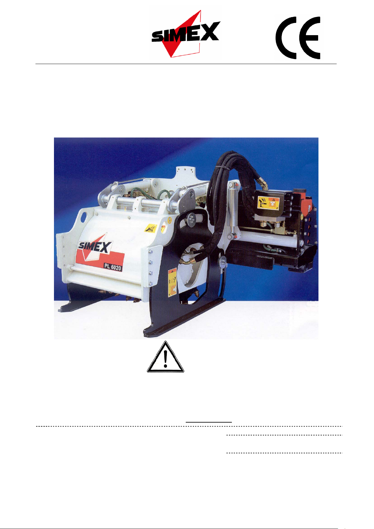
COLD PLANER
PL 4520 - PL 5020 - PL 5520 - PL 6020 - PL 7520
SIMEX s.r.l.
Via Newton,31
40017 - San Giovanni in Persiceto (BO) Italy
Tel +39.051.6810609 fax +39.051.6810628
www.simex.it - simex@simex.it
No part of this manual may be reproduced or translated
without prior written permission from its owner. The
information and illustrations contained in this manual are for
illustrative purposes only. SIMEX S.r.l. reser
ves the right to
make changes to the machine at any time without any prior
notice.
Code: SXNM153D07 (English)
Type:
……………………………(C.A.T.)
Serial n° ……………………..

TABLE OF CONTENTS
1. Sound power levels detected ................................................................................................................4
2. Declaration of conformity ......................................................................................................................5
3. Symbols...................................................................................................................................................6
4. Safety and hazard stickers ....................................................................................................................7
5. General precautions for use..................................................................................................................9
6. Technical characteristic.......................................................................................................................10
6.1 Machine description ............................................................................................................................10
6.2 Overall dimensions..............................................................................................................................11
6.3 Specifications and performance..........................................................................................................12
6.4 Main machine parts.............................................................................................................................13
6.5 Environmental conditions....................................................................................................................15
6.6 Permitted uses ....................................................................................................................................15
6.7. Residual risks......................................................................................................................................15
6.8 Safety devices.....................................................................................................................................16
7Delivery and unloading ........................................................................................................................17
8Handling, transportation and lifting....................................................................................................18
9Use .........................................................................................................................................................19
9.1 Preliminary checks..............................................................................................................................19
9.2 Procedure for getting on and off the prime mover ..............................................................................19
9.3 Machine/prime mover matching..........................................................................................................20
9.4 Hydraulic connection of the standard machine with 3-line hydraulic system to the prime mover.......22
9.5 Hydraulic connection of the standard machine with 5-line hydraulic system to the prime mover.......23
9.6 Hydraulic disconnection of the standard machine with 3- or 5-line hydraulic system from the prime
mover ..................................................................................................................................................24
9.7 Disconnecting the machine from the prime mover..............................................................................25
9.8 Planing depth adjustment....................................................................................................................26
9.8.1. Setting the zero position for planing depth adjustment.......................................................................27
9.9 Cutter drum removal and refitting........................................................................................................28
9.10 Mechanical floating tilt device with spring jack....................................................................................29
9.11 Starting up standard machines ...........................................................................................................30
9.12 Side shift operation on the standard machine with 3-line hydraulic system .......................................32
9.13 General operating conditions..............................................................................................................33
9.14 Side-by-side planing............................................................................................................................34
9.15 Stopping the machine in normal conditions ........................................................................................35
9.16 Emergency stops.................................................................................................................................35
9.17 Parking ................................................................................................................................................35
10 Maintenance................................................................................................................................................36
10.1 Cutter drum inspection........................................................................................................................37
10.2 Tool integrity assessment (teeth)........................................................................................................38
10.3 Tool replacement (teeth).....................................................................................................................40
10.4 Machine cleaning ................................................................................................................................40
10.5 Structural integrity assessment...........................................................................................................40
10.6 Nut and bolt tightness test...................................................................................................................40
10.7 Check the support skids for wear........................................................................................................41

3
10.8 Depth adjustment mechanism lubrication...........................................................................................41
10.9 Shock absorber lubrication..................................................................................................................42
10.10 Lubrication of the depth adjustment shaft mounts..............................................................................42
10.11 Hose inspection...................................................................................................................................43
10.12 Drain line safety cap check.................................................................................................................43
11 Storage instructions...................................................................................................................................44
12 Recommissioning.......................................................................................................................................44
13 Spare parts and accessories.....................................................................................................................44
14 Disposal.......................................................................................................................................................44
15 Troubleshooting .........................................................................................................................................45
16 Optionals .....................................................................................................................................................47
16.1 Special drums......................................................................................................................................47
16.2 Removable skid...................................................................................................................................48
16.3 Misting unit..........................................................................................................................................49
16.4 Hydraulic tilt adjustment......................................................................................................................50
16.5 Hydraulic depth adjustment.................................................................................................................51
17 Charts.....................................................................................................................................................53
17.1 Maximum screw tightening torques.....................................................................................................53
17.2 Tightening torques for hose fittings.....................................................................................................53
17.3 Tightening torques for hoses...............................................................................................................53
18 Guarantee....................................................................................................................................................54
19 Control circuit diagrams............................................................................................................................55

Dear Customer,
Thank you for choosing a “SIMEX s.r.l.” product! We are pleased to give you this manual, which we hope will
help you get the most out of our product and enhance your work.
Inside this manual the user will find all the information required to use the machine correctly. The trade name
of the machine is stated on the front cover of this manual. You are advised to follow all the instructions
contained in this handbook exactly and to store it carefully in an appropriate, accessible place. The manual
must be kept for future reference until the machine is scrapped. If the machine is sold, the vendor is required
to pass on the manual to the new owner.
The information in the manual is arranged into topic-based chapters. The information is originally supplied by
the manufacturer in Italian. In order to meet certain legal or business requirements, the original information is
translated into the other official languages.
The contents of this manual may be altered without prior notice, with no further duties ensuing, in
order to include changes or upgrades made to the units already despatched.
Please note that, for reasons of visibility and clarity, certain figures may show the equipment
arranged in ways which do not correspond to the correct set-up for use.
No part of this handbook may be reproduced or translated without the manufacturer’s permission.
“Original Instructions”
1. Sound power levels detected
The table below shows the sound power levels detected (LwA) according to EN ISO 3744, for the various
self-levelling planers.
SELF-LEVELLING PLANER PL 4520 LwA 86 dB +/- 3dB
SELF-LEVELLING PLANER PL 5020 LwA 87 dB +/- 3dB
SELF-LEVELLING PLANER PL 5520 LwA 86 dB +/- 3dB
SELF-LEVELLING PLANER PL 6020 LwA 87 dB+/- 3dB
SELF-LEVELLING PLANER PL 7520 LwA 87 dB+/- 3dB

5
2. Declaration of conformity
The declaration of conformity is filled in and signed by SIMEX S.r.l.’s legal representative, and attached to this
manual. Following an example of the declaration of conformity.

6
3. Symbols
The chart below outlines the symbols used in this handbook (those considered the most important).
WARNING – HAZARD: this alerts the user to situations or problems which could either
jeopardise personal safety or lead to fatal injuries.
IMPORTANT: this alerts the user to situations or problems linked to machine efficiency rather
than safety.
“OPERATOR”: This is the appropriately trained staff member who is authorised to install,
operate, adjust, clean and transport the machine.
“MAINTENANCE ENGINEER”: This is the person(s) trained and authorised to work on the machine for
routine maintenance and the replacement of certain components.
“MACHINE”: This is the interchangeable equipment outlined in section 6.1.
“PRIME MOVER”: This is the vehicle on which the interchangeable equipment is fitted. The
abbreviation “p.m.” may also be used in this manual.
“RIGHT-HAND SIDE AND LEFT-HAND SIDE”: These are the sides of the equipment determined in relation
to the prime mover driving point.

7
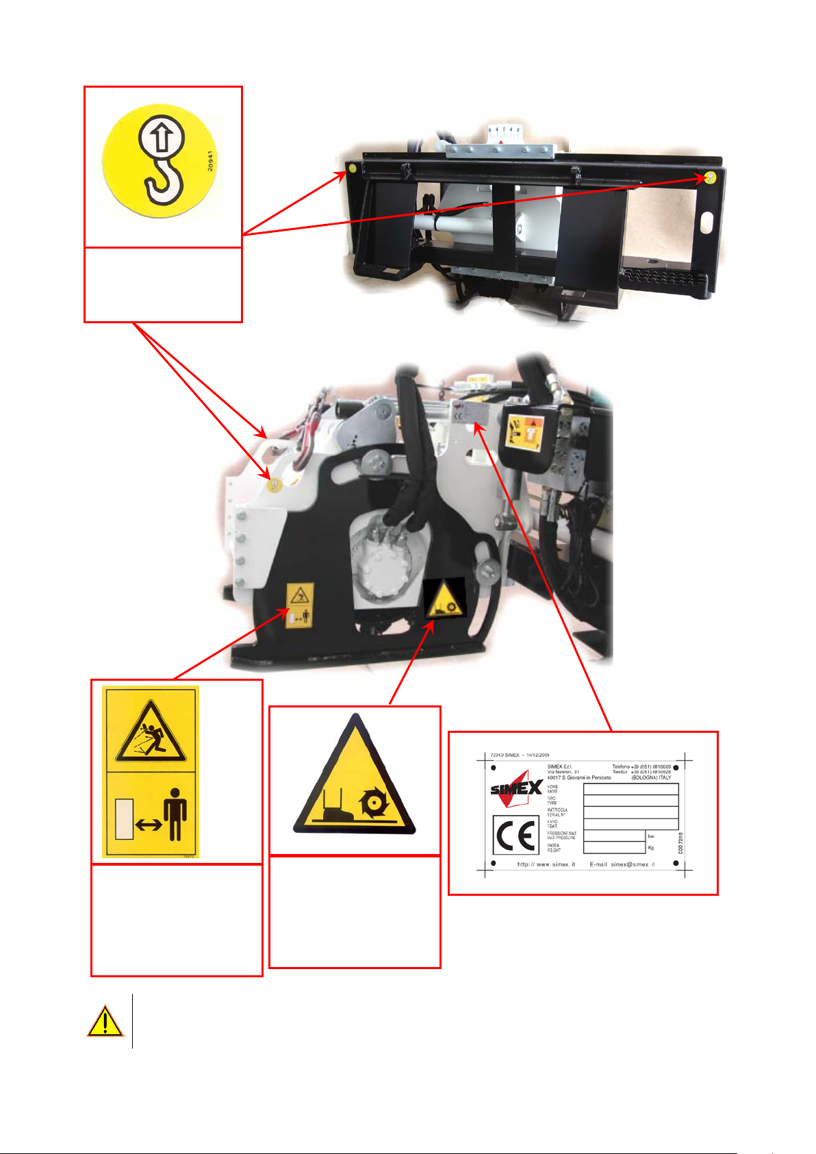
4. Safety and hazard stickers
Location of the data plate and the safety and hazard stickers on the machine.
Warning:
READ THE MANUAL
CAREFULLY BEFORE
USING THE MACHINE
Code: 20944
Warning:
RISK OF CRUSHING STICKER;
DO NOT ACCESS THE AREA OF RISK
Code: 20937
Warning:
NO WORK MAY BE CARRIED OUT ON
THE MACHINE
UNTIL DRUM
ROTATION HAS STOPPED
Code: 20942
Warning:
READ THE MANUAL
CAREFULLY AND
REMOVE THE KEY
FROM THE CONTROL
PANEL BEFORE
MAINTENANCE OR
REPAIRS
Code: 20943
Requirement:
YOU ARE REQUIRED TO
WEAR APPROPRIATE
PERSONAL PROTECTION
EQUIPMENT
Code: 75104
8
Always heed the warnings on the plates and transfers/stickers. Failure to do so may result in death or
serious injury. Make sure the plates and transfers/stickers are always in place and legible. If this
is not the case, affix or replace them, obtaining the materials required from the manufacturer.
4 stickers
HOOK UP POINT
FOR LIFTING PURPOSES
Code: 20941
Affixed to both sides of
the machine
Warning:
KEEP CLEAR OF THE
MACHINE (MIN. 10 m)
Code: 75572
Warning:
CUTTER DRUM ROTATING
Code: 74796

9
5. General precautions for use
•The operator is directly accountable for the machine’s safe operation.
•Read this manual carefully before proceeding with installation, start-up, use or any servicing
of the machine.
•The aim of this handbook is to familiarise the operator, through the figures and explanations,
with the basic rules and criteria to follow during machine use and maintenance.
The following procedures are essential to guarantee safe operation:
•Check that the machine has not suffered any damage during transportation and i
f it has,
advise the manufacturer or area agent straight away.
•Make sure the machine is only used by authorised adults with appropriate training.
•Make sure the prime mover due to be used has all the dead-man’s controls fitted and that
they are in perfect working order.
•Ensure all non-members of staff are kept clear of the machine when it is in use (safety
distance of at least 10 metres). Cordon off the work area. This operation has to be done by
the operator.
•Stop working if anyone or any animals should enter the work area.
•Clean the machine regularly, removing all foreign matter which could impair operation or
cause injury to the operator.
•Before using the machine, make sure all the safety devices are correctly in place and in
good condition; if any broken devices are found, replace them immediately.
•Make sure all the hoses and fittings are properly attached.
•Do not carry out any maintenance work until you have read the instruction manual, and
always remove the ignition key from the prime mover before starting.
•Any repairs needed must be carried out solely by authorised personnel using original spare
parts. If this rule is not applied, the user could be exposed to serious risks.
•All inspections of the hoses and fittings must be carried out using
suitable personal
protection equipment (goggles, gloves and clothing to protect against contact with the skin).
•Do not leave the machine installed on the p.m. when the p.m. is unattended
in the work
area.
•Do not wear anything which might get caugh
t in the moving parts, such as unsuitable
clothing, shoes, shirts etc. You are recommended to wear garments approved for accident-
prevent purposes, e.g. helmets, non-slip shoes, headphones, and safety goggles and gloves.
Check with your employer as to the safety regulations in force and the accident-prevention
devices required.
•Do not wear rings, bracelets, necklaces, watches, or scarves.
•If you have long hair, keep it tied back.
10
6. Technical characteristic
6.1 Machine description
The Self-levelling Planer, hereinafter referred to as the ‘machine’, is a cold planer for working on flat surfaces
made of asphalt or concrete. It can be fitted onto the majority of skid steer loaders, and is ideal for lengthwise
trench cutting on horizontal ground.
The self-levelling feature of the side support side plates ensures the side plates are kept parallel to the
ground, guaranteeing the utmost stability and perfect spoil containment. It also maintains the set planing
depth in all conditions. The depth can be uniform or set differently for each side (RH/LF) using adjustment
screws (standard version) or hydraulic cylinders (optional accessories).
The planer must be positioned so that the sides grip the ground. For increased safety, it is advisable to lift the
rear wheels of the skid steer loader a few centimetres off the ground.
To facilitate planing on a surface which is not parallel to the surface on which the primer mover wheels are
resting, the planer can be tilted transversally either automatically (on the standard machine) or using a
hydraulic cylinder (optional).
If planing is required up to and beyond the external edge of the prime mover, a side shift, operated by a
hydraulic cylinder, allows the operator to shift the machine from the central position to the right-hand side.
There is also an optional water misting system available, which features a tank that can be mounted on either
the side shift or the prime mover's roof and is used for dust abatement during planing.
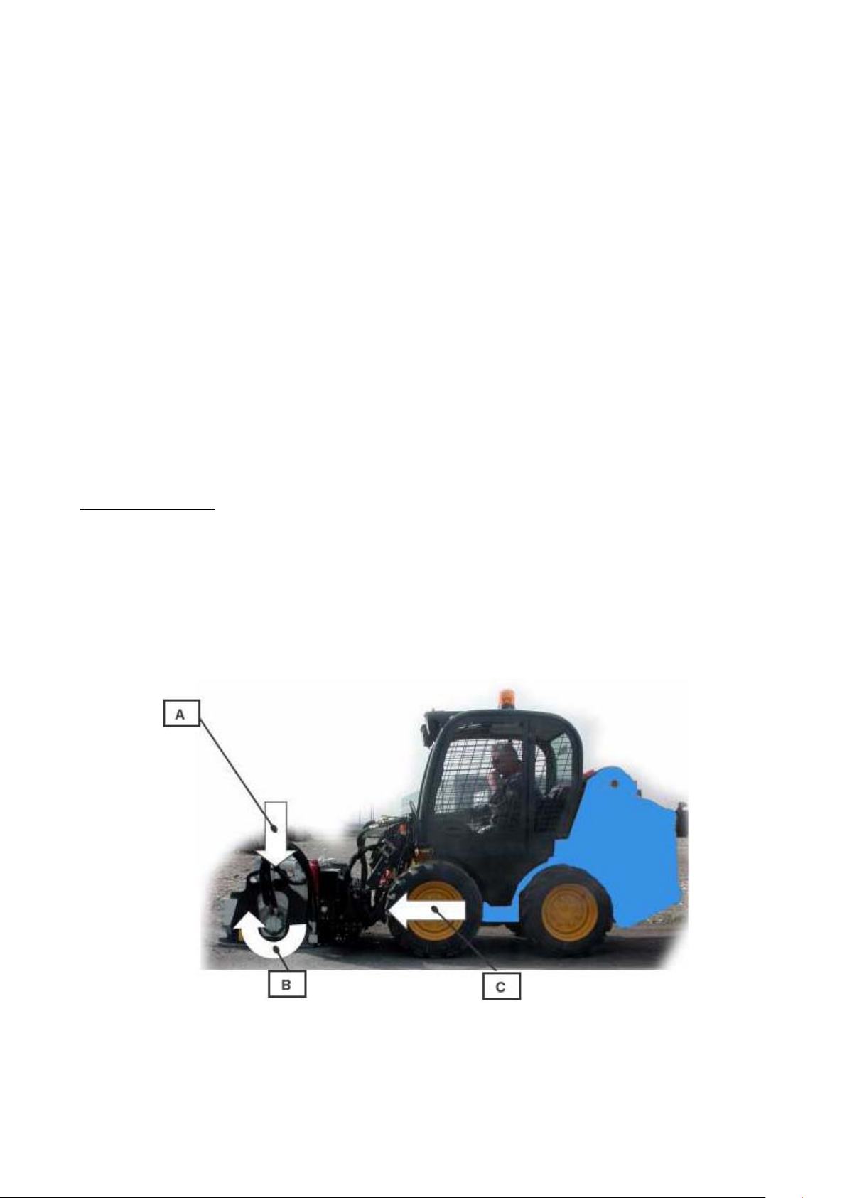
Operating principle:
The planing action is obtained by combining the rotary motion of the cutter drum (driven by the hydraulic
motor onto which it is fitted directly) and - at the same time - the side shift motion of the prime mover on which
the machine is installed.
The hydraulic motor drives the cutter drum directly, which rotates in the direction indicated by the arrow in the
figure, cutting away and crushing up the material in question (asphalt, concrete and suchlike). The material is
removed by hard metal teeth positioned on the said drum.
The hydraulic power is transmitted by the prime mover to the machine via hoses.
A = Maintenance of grip on ground
B = Cutter drum rotation direction
C = Direction of work

11
6.2 Overall dimensions
PL A B B1 (*) C D E
4520 1680 1180 1270 900 450 610
5020 1680 1250 1350 950 500 665
5520 1680 1180 1270 900 550 710
6020 1680 1250 1350 950 600 765
7520 1680 1300 1400 960 750 910
(*) Version with water tank mounted on side shift unit.

12
6.3 Specifications and performance
Technical characteristic Unit of
measurement
Models
PL 4520 PL 5020 PL5520 PL 6020 PL 7520
Operating pressure
Bar 300÷160 300÷160 300÷160 300÷160 300÷180
Required oil flow
l/min 65÷140 90÷160 70÷140 90÷160 110÷180
Drum speed
rpm 150÷230 130÷200 150÷230 130÷200 120÷190
Max. hydraulic motor power kW 35 45 35 45 50
HP 48 61 48 61 68
Weight (*)
kg 770 840 825 930 1050
(*) Standard machine set-up, with no optionals, no built-in water system, and with a universal adapter
plate.
IMPORTANT In the event of set-ups featuring optionals, the correct weight (which is different to the
one stated in the table) will be specified on the CE data plate.
Example of how to calculate the hydraulic motor power:
Q (l / min) x P (bar)
= A (HP) / 1.36 = A (kW)
450
Key:
Q= Capacity P= Pressure A= Power
N.B. The flow and pressure rates stated in the equation above must be measured at exactly the same time,
using a precision tool. The measurement must be carried out by a skilled member of staff.
Quoting the "model" and the "serial number" will make it easier for our Service Department to respond to your
enquiries quickly and effectively.
Make sure you have the machine’s model and serial number to hand whenever you have to contact our
Service Department. The registration details can be found on the identification plate (see chapter 4).
13
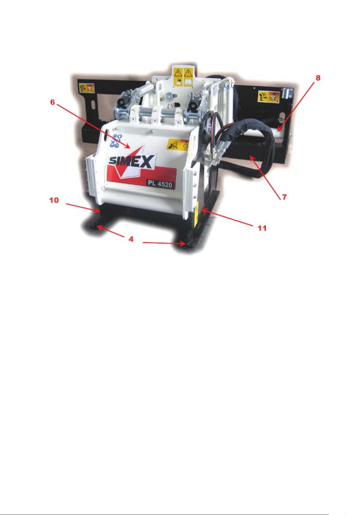
6.4 Main machine parts
1. Cutter drum;
2. LH work depth adjustment screw;
3. RH work depth adjustment screw;
4. Skids;
5. Hydraulic motor;
6. Drum inspection cover;
7. Side shift;
8. Side shift hydraulic cylinder;
9. Transversal tilt signal light;
10.Right-hand side plate;
11.Left-hand side plate;
12.Spring jack;
13.Valve for electro hydraulic controls (on machines with 3 hydraulic lines only);
14.By-pass valve lock (on machines with 5 hydraulic lines only);
15.Depth adjustment crank;
16.Tool removal spanners.

14

15
6.5 Environmental conditions
When temperatures are below -10°C, before starting the machine, check that the prime mover has warmed
up the hydraulic system to correct temperature.
The use environments must comply with the regulations in force concerning hygiene and safety in the
workplace.
•No naked flames and suchlike near the machine.
•Do not use the machine in areas where there is a risk of explosion or fire. This machine is not
built to work in an explosive environment (ATEX Directive).
6.6 Permitted uses
The machine is designed to be mounted on a prime mover in order to carry out cold planing on hard, compact
materials such as asphalt and concrete.
Use of the machine is only permitted if mounted on a prime mover carrying a declaration of conformity with
directive 98/37/EC and/or 2006/42/EC and the legislation in force, and if it meets the technical requirements of
the machine to be mounted (outlined in paragraph 6.3.).
Any other use than that expressly provided for herein should be considered mishandling and
therefore not permitted.
When working in tunnel or during night time or with low visibility due environmental conditions, the working are
has to be illuminated (min 200 lux) either by the prime mover or by working area fir o mobile lights.
SIMEX S.r.l. cannot be held responsible for any mishandling of the machine or any changes or alterations
made to it.
•
The machine must never be shifted sideways when the drum is in use.
•Any use of the machine which does not comply with the us
es specified in this
installation, use and maintenance manual is strictly prohibited.
•Do not stand, move or work on floors or any non-bearing structures.
•
Planing must never be carried out on curved ground where the radius of the curve is
below 25 m.
6.7. Residual risks
When the machine is in use, the following risks may arise:
- electric shocks from contact with underground power lines;
- fire and explosions through contact with underground gas lines;
- explosion of explosive devices buried in the area as a result of wars/conflicts that may have occurred
in the past.
Anyone standing in the vicinity of the machine may be exposed to the following risks:
- risks originating from blows, catching or shearing, as result of accidental contact with the cutter
drums;
- risk of crushing between the machine and the prime mover;
- risk of rubble (stones, blunt objects, etc.) being thrown out;
- risk of falling spoil (when working on uneven ground or on surfaces at different heights).

16
6.8 Safety devices
•The safety guards must NEVER be tampered with.
•The machine must NEVER be used without the safety guards fitted.
•Use always suitable PPE for any maintenances’ operation.
•The working tools (teeth) while working can reach an high temperature level. Before
touch the working tools (teeth) wait until they cool down and suitable protection gloves
MUST be used.
1-
Guard for the motor hoses - only featured on the
version with 3 hydraulic lines (pressure, return and
drain);
2- Drum inspection cover. To open the cover the
fixing bolts needs to be unscrewed. Te bolts have
retaining fastener seeger rings that will not allow to
loose the bolts when they are unscrewed. Do not
remove the bolts from the cover after it is opened.

17
7 Delivery and unloading
The machine is normally transported and delivered securely fastened to a pallet, in a stable position, and duly
wrapped in plastic sheeting. The type of packing, though, may vary according to the desired means of
transport and the destination. For carriage by air, the machine is packed inside a suitable wooden crate. All
the equipment despatched is checked prior to delivery to the customer.
On receipt of the machine, check it for any damage (major breakages or dents) caused during
transportation. If any are found, the carrier must be alerte
d immediately and the statement
“Accepted conditionally” must be added to the delivery note.
In the event of damage, give notice of the fact to the carrier in writing within 8 days of receipt of the
machine.
If, upon delivery, major damage caused during transportation is noted, or any parts that should be
included are found to be missing, SIMEX s.r.l. must be notified of the situation promptly.
It is also essential to check the equipment delivered against the information given in the itemised
shipping document.
The packed unit must be unloaded with the utmost care using lifting means with a suitable
capacity (e.g. fork lift truck or other appropriate means).
Next, the entire unit must be placed on a flat, stable surface.
All load handling operations must be carried out in compliance with the regulations in force
concerning safety in the workplace.
Dispose of the packing in compliance with the regulations in force in the country of use; do not
fly tip it.
18
8 Handling, transportation and lifting
If the type approval of the prime mover to travel on normal roads does not extend to the
machine, it must be removed before transportation on open roads.
Only small movements may be performed on the worksite when the machine is mounted on
the prime
mover; during these movements shifting must be carried out at low speeds with
the machine located close to the ground and the prime mover arms as closed up as
possible; all people and things must be kept a safe distance away.
The machine must always be removed from the prime mover before the vehicle is driven up
loading ramps.
The machine must not be operated during handling.
Handling over short stretches (in the workplace):
A- Use the prime mover, leaving the machine attached.
B- Secure the machine to a pallet, and handle it with a fork lift truck or a transpallet.
Handling over long stretches:
−Secure the machine to a pallet, using a fork lift truck or a transpallet for handling, then load it onto the
means of transport (lorry, train, etc.).
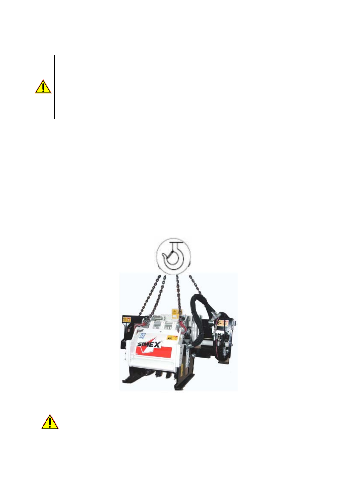
Lifting from one surface to another (e.g. to load onto a lorry):
−Use a lifting crane or truck with a suitable capacity for the weight specified on the CE plate. Connect the
cables or chains at the four points shown with the relative stickers (see chapter 4). When lifting, use
hooks with the CE marking (see figure below).
Check that the capacities of the cables, chains and lifting and transportation means in general are
compatible with the machine weight specified on the EC data plate.
When attached to the prime mover, keep the machine close to ground level (safety height: 0,5 m)
during handling.
Shifting is only permitted on flat, or slightly loose ground, as long as stability is never jeopardised.
Check that the pallet on which it will be stored is in suitable condition.

19
9 Use
The fitter is responsible for checking that the prime mover meets the equipment’s
specifications (see section 6.3).
The machine may only be fitted on prime movers carrying a declaration of
conformity to directive 98/37/EC and or 2006/42/EC (e.g. those fitted with dead-man’s
controls, which disable the machine’s controls when, for example, there is no-one in
the driving seat, etc).
9.1 Preliminary checks
Before proceeding with the connection to the machine, the prime mover must undergo checks to ensure:
A. that all the featured safety devices work properly;
B. that all the quick couplings and other components related to the coupling to the prime mover
are in good condition.
9.2 Procedure for getting on and off the prime mover
(for self-levelling planers applied to skid loaders where the driver’s seat is accessed from the
front of the p.m.)
GETTING ON (on the right-hand side of the machine).
A= place your left foot on the lower step on the self-levelling planer (fig. 1);
B= with your weight on your left foot, step up onto the self-levelling planer, placing your right foot on the upper
step (fig. 2);
C= with your weight on your right foot, step up onto the prime mover, placing your left foot on the non-slip step
(fig. 3).
To GET OFF, carry out the steps outlined in figures 1, 2 and 3 in reverse order.
If the lower step is fitted on the left-hand side of the machine, the procedures to get
on and off must be carried out as outlined above but using the opposite foot to that
specified for each movement.
When getting on and off the prime mover, always use the non-slip steps.
Make sure your shoes are not muddy or covered with anything else that could make you
slip.
On no account should you get off or on from the front of the machine.
20
9.3 Machine/prime mover matching
The machine must be mounted on the prime mover’s arm instead of the standard bucket, using any of a
number of connection types. Apart from the general instructions given below, the procedures outlined in the
prime mover’s manual (see specific section on the application of equipment) must also be followed.
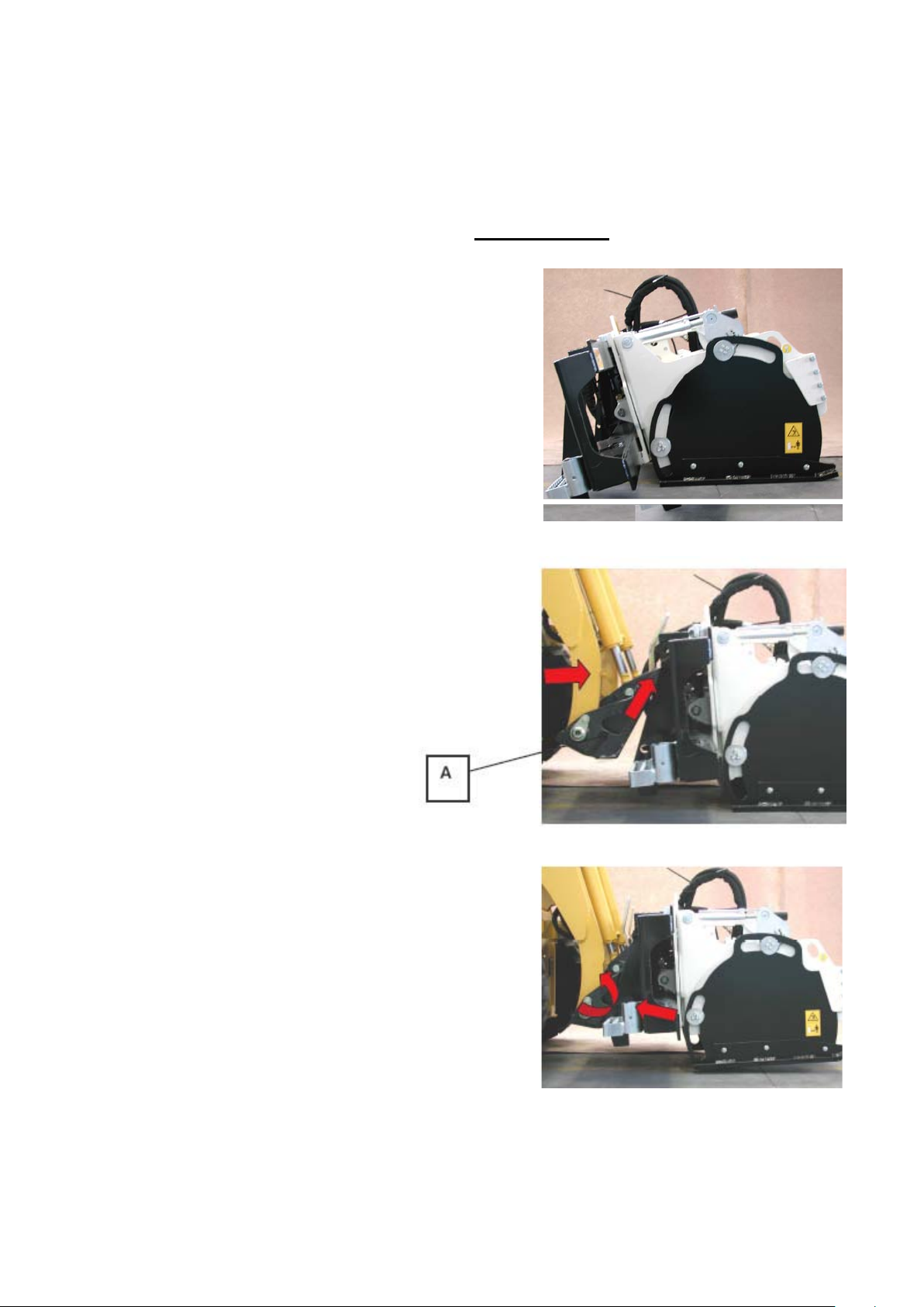
Example of the operations that must be carried out for a standard coupling
:
1- Position the self-
levelling planer on flat,
compact ground, in the non-operative position,
and away from ditches, stores of fuel or any
other substances, and electrical substations
(fig. 1 opposite).
1
2- Move the prime mover towards the machine
slowly, with the loader arm lowered, so that
the adapter plate can be positioned (ref. “a” in
fig. 2 opposite) beneath the upper lip of the
adapter plate fitted on the machine.
Move forwards until it is resting on the lip, as
shown in figure 2 opposite.
2
3-
Manoeuvre the prime mover using the
hydraulic controls so that the adapter plate
moves back towards it (ref. “A” in fig. 2
opposite) until it is resting fully on the
machine’s coupling area, as shown in fig. 3
opposite.
3
This manual suits for next models
4
Table of contents


