Spartan Utilimaster W Series User manual

1
03103436-A10005 Rev. B 574-848-2200
Service
Guide
Rear Roll-up Door
W-Series
Door, W-Series Rear Roll-up
Do NOT use the rear door pull strap to support yourself when entering or exiting the rear. The strap can
break or pull the door down on you. Use the grab handles for aid getting in and out of the back.
A roll up-door counterbalance spring is wound under high tension. Only qualied technicians should
adjust this spring.
A moving door can cause injury or death. Stand clear of the opening while the door is moving.
Read the safety and warning decals provided by the manufacturer. Never paint over the decals, and
replace them if they are faded.
To prevent damage to the cargo or vehicle, be sure that the rear door is closed and latched before driving
the vehicle.
The information in this document applies to our most common roll-up door option. If your vehicle is
equipped with a different roll-up door, refer to the door manufacturer's service guide for operation,
adjustment, and maintenance instructions.

2
03103436-A10005 Rev. B 574-848-2200
To unlock the door from the outside, insert the key in the lock and turn clockwise 1/4 turn until thumb
lock pops out. Rotate key
counter-clockwise 1/4 turn, and remove the key from the lock.
To open the door from the outside, push down on the lower door lift handle to relieve tension on the
latches and rotate the release handle clockwise until the latches release.
To open the door from the inside, push down on the door to relieve tension on latches, and push the
lever toward the passenger’s side of vehicle until the side latches release.
To lock the door from the outside, insert the key and turn clockwise
and push in on thumb lock.
Rear roll-up door lift handle
Rear roll-up door release handle

3
03103436-A10005 Rev. B 574-848-2200
Adjustment
Adjusting the roller bracket up moves the panel in. Adjusting the roller bracket down moves the panel out.
The door may jam if adjusted too tightly.
1. Check that the door does NOT bind in the track, and is centered in opening.
2. Position top roller brackets so that the top panel is vertical and seals along both the top and sides.
3. Tighten nuts.
Nut location on top roller bracket

4
03103436-A10005 Rev. B 574-848-2200
Removal
The counterbalance springs are wound under high tension and can cause severe injury or death. Release
the tension as described prior to performing repairs.
Installation, repairs, and adjustments must be made by trained service personnel using proper tools and
instructions.
Use two heavy-gauge steel winding bars with the proper dimensions. Do NOT use bent winding bars,
screwdrivers, or punches for spring winding.
1. Close door.
2. Remove cables.
3. Remove the nuts, washers, and bolts from stops located at the
end of each track and set aside.
4. Slowly move door up and remove from tracks.
Installation
1. Lift and slowly slide door into top of tracks.
2. Install cables.
3. Secure stops located at the end of each track with bolts,
washers, and nuts.
4. Adjust spring.
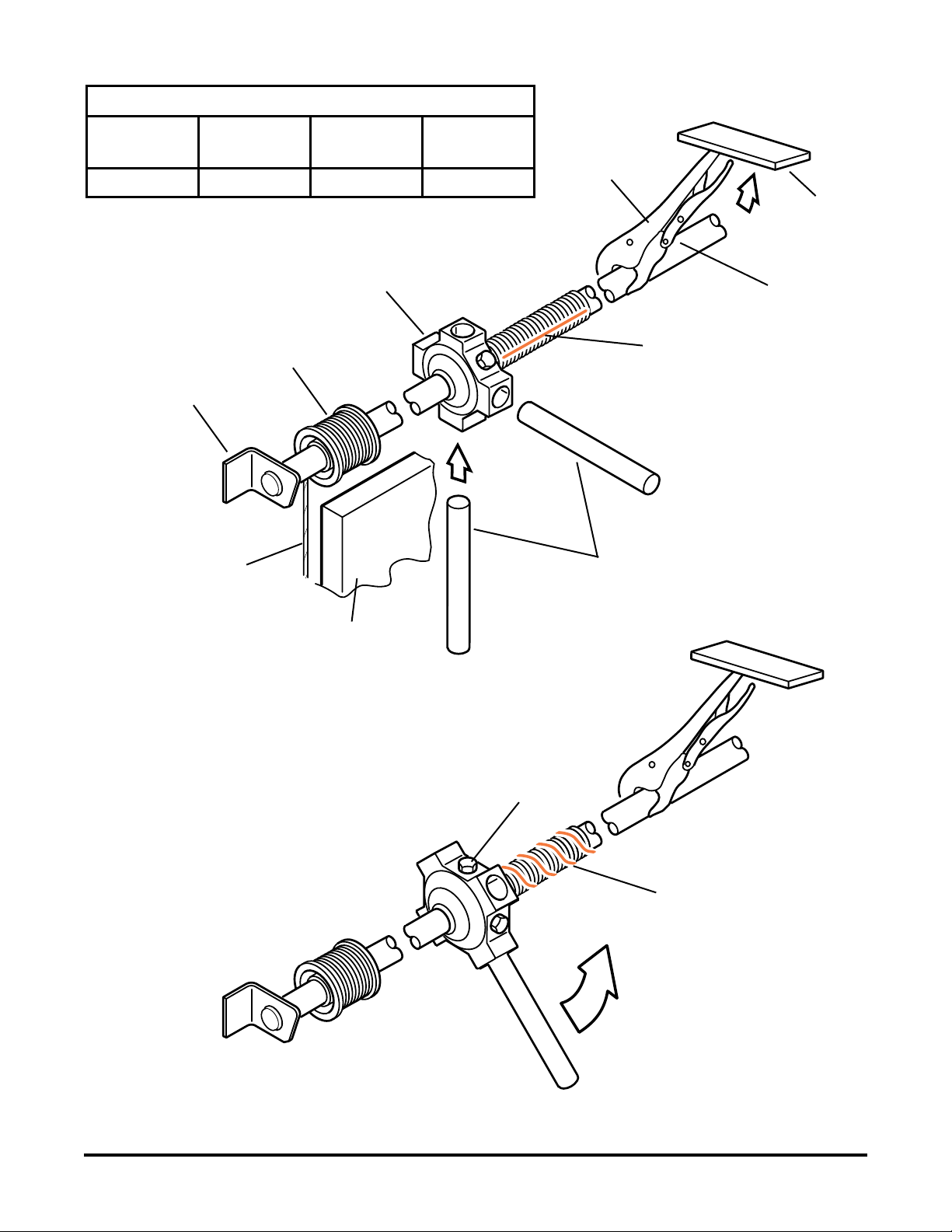
Cables
Removal
To avoid injury or damage to the equipment, do NOT raise the door with the winding bar in place.
It is recommended to replace both cables even if only one cable is frayed or damaged.
1. Close door.
2. Insert a winding bar that is 1/2" in diameter by 10" long into one of
the spring-winding plug holes.
3. Raise the bar to allow insertion of a second winding bar into the
lower hole.
4. Release the tension enough to allow the second bar to rest against
the top panel.
Stop bolt
Spring winding plug holes

5
03103436-A10005 Rev. B 574-848-2200
5. Release the cable drum from the shaft by loosening (2) set screws on the cable drum and remove
cable.
6. Remove the cotter and anchor pins to remove cable from bottom door panel.
Installation
Ensure the drums are against the counterbalance shaft bearings, the setscrews are properly tightened,
and the cables have equal tension.
Rotating the counterbalance assembly too far may cause the cables to jump off the cable drum.
The cable must be wound from the outermost groove toward the inside of the drum.
1. Secure the cable end to the anchor bracket with an anchor pin.
2. Secure anchor pin with a cotter pin.
3. Enter loose end of cable into slot in open end of cable drum.
4. Kink cable to follow rst groove in drum and wind the spring so that the cable follows the
grooves tightly. Cable must come off the bottom of the drum to be installed properly. Rotate
spring by hand to put tension onto cable.
5. Slide spring assembly along shaft until cable from bottom of drum is in line with cable anchor
and tighten setscrews.
6. Adjust spring.
Cable drum
Cotter and anchor pins

6
03103436-A10005 Rev. B 574-848-2200
Panels
Do NOT drill through the outside panel of a hollow core door.
Removal
Before removing the bottom panel, the cables needs to be removed.
Remove hardware from panels to be used on replacement panels.
1. Close door and clamp track below panel to be removed.
2. Remove rivets in hinges. Insert a punch in one of the rivet holes to stabilize the panel while
removing the remaining rivets.
If removing the top panel, remove the bolts and washers in both top rollers.
3. Remove rollers.
4. Lift the door panels, above panel to be replaced, into horizontal track and secure with clamps on
the track.
5. Remove punches and lift out the panel.
Top roller bracket
Roller hinge
Do NOT drill through the outside panel of a hollow core door.

7
03103436-A10005 Rev. B 574-848-2200
Installation
1. Clamp the panel into position and lower the door from the horizontal track.
2. Drill the holes on the new panel, using the holes on the hinge as a guide.
If installing the top panel, secure the bolts and washers in both top rollers.
3. Install rollers.
4. Secure hinges with rivets.
If installing the bottom panel, the cables need to be installed.
Install any applicable hardware on panels.
Rollers
Removal
1. Open door.
2. Remove nuts that secure the roller retainer.
3. Remove roller from track and set aside.
Installation
1. Insert hinge or roller bracket into retainer.
2. Place roller into track.
3. Install the hinge or roller bracket and tighten the nuts.
4. Lubricate with a light oil (P/N 10997689).
Bottom roller bracket
Roller hinge
RIVETS

8
03103436-A10005 Rev. B 574-848-2200
Seals
Brush Seal Removal
1. Open door.
2. Remove rivets.
3. Use a at-blade screwdriver to pry apart the crimped extrusion.
4. Remove seal and discard.
Brush Seal Installation
1. Test t brush seal and cut to proper length with bolt cutters.
2. Insert the brush seal into the extrusion end.
3. Crimp the extrusion.
4. Secure seal with rivets.
Top Seal Removal
1. Open door and clamp track to prevent door from moving.
2. Use a at-blade screwdriver to pry apart the crimped extrusion
and remove seal.
Top Seal Installation
1. Slide seal into extrusion.
2. Crimp the extrusion.
Threshold Seal Removal
1. Open door and clamp track to prevent door from moving.
2. Remove the Phillips head screws from the threshold seal.
3. Remove seal and discard.
Threshold Seal Installation
1. Place the seal, angle edge rst, into the extrusion and rotate into position.
2. Secure with #8 screws.
Top seal
Uncrimp both ends of the
bracket to remove the old seal.
Brush seal
Bottom seal

9
03103436-A10005 Rev. B 574-848-2200
Spring
Adjustment
A properly counterbalanced door should remain in the same position when stopped. If the door leaves
the oor by itself, the spring is wound too tightly, and a few quarter turns should be released. If the door
tends to drop when stopped, a few more quarter turns should be added.
1. Close door and clamp counterbalance shaft from the inside with handle of locking pliers against
the ceiling to keep cables tight. Protect the roof from the pliers with a piece of plywood or sheet
metal.
2. Insert a winding bar that is 1/2" in diameter and 10" long into one of the spring-winding plug
holes.
3. Loosen setscrews on spring-winding plug.
4. Insert a second winding bar into one of the spring-winding plug holes.
5. Raise the bar to allow insertion of second winding bar into next spring-winding plug. Continue
to raise bar to wind spring, approximately 11 complete revolutions.
6. Tighten setscrews.
7. Remove locking pliers and winding bars.
8. Cycle door to check operation.
9. Adjust again if necessary.
10. Lubricate with a light oil (Utilimaster P/N 10997689).
10
03103436-A10005 Rev. B 574-848-2200
Winding counterbalance spring
Right Hand
(Curbside)
Left Hand
(Roadside)
Chalk mark
Support Bracket
Chalk Mark
(Compressed Spring)
Winding Bars (See
Dimensions Table)
Locking Pliers
Against Ceiling
Rotate Toward the
Ceiling to Compress Spring
Spring Winding Plug
Cable
Door Top Panel
Cable Drum
Protective
Flat Stock
Setscrew
NOTE: This vehicle was designed
using English (S.A.E.) measurements.
Utilimaster provides metric
conversion equivalents as a courtesy,
but Utilimaster does not warrant
metric values given in this
manual.
Winding Bar Dimensions
Door
Type
Diameter
(Inches)
Diameter
(Millimeters)
Approximate
Length
W-Series 3/8" 95.2 mm 10"
Counterbalance
Shaft

11
03103436-A10005 Rev. B 574-848-2200
Removal
1. Remove cables.
2. Remove (2) bolts located on anchor brackets.
3. Remove spring and set aside.
Installation
1. Place spring into anchor brackets and secure with (2) bolts, lock washers, and nuts.
2. Install cables.
Anchor bracket bolts
12
03103436-A10005 Rev. B 574-848-2200
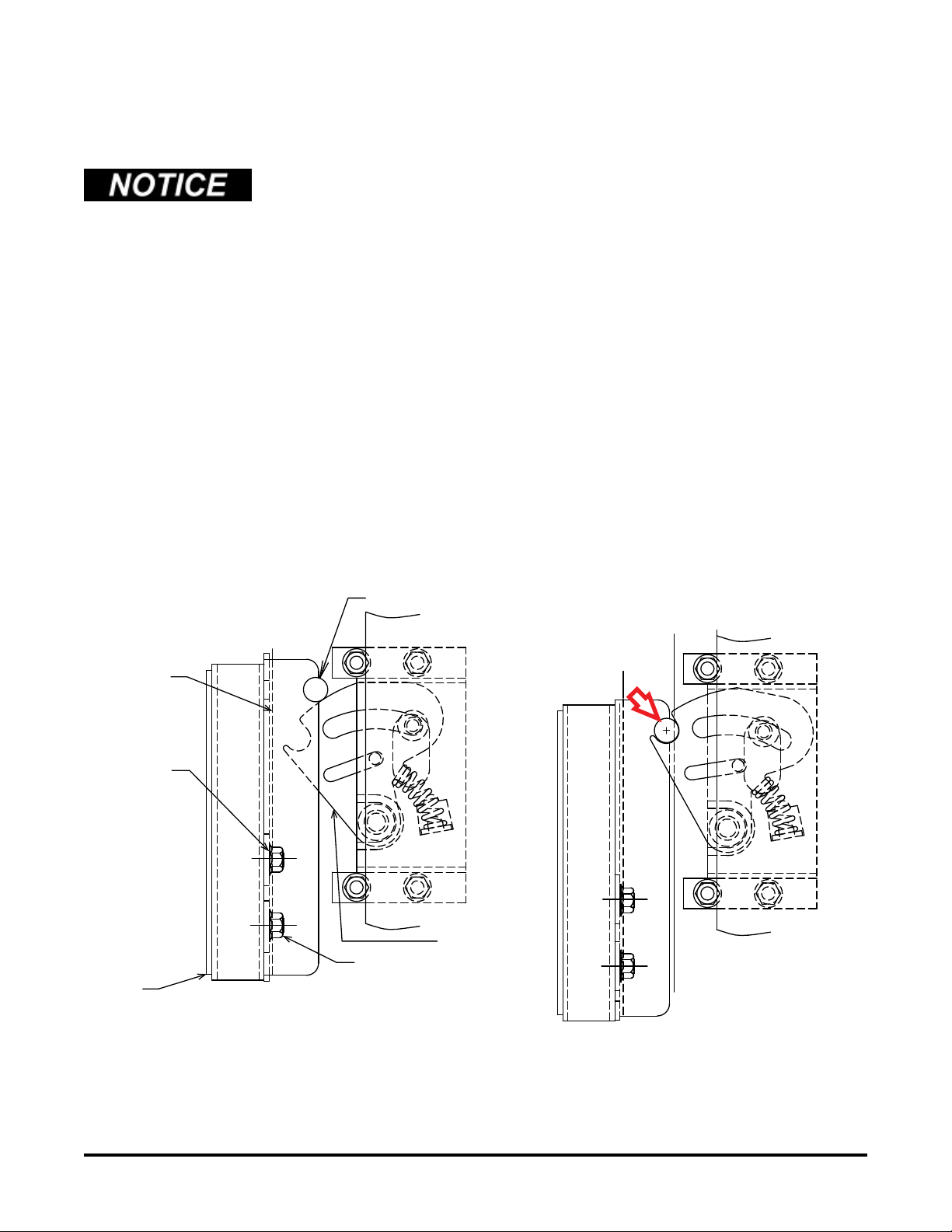
Rear Roll-up Door Slam Lock Adjustment
On rear roll-up doors with slam locks, adjust the latch if problems occur with the door latching or
sealing.
Some doors may have a two-point fan-type latch with primary and secondary positions. Adjustment
principles for both are similar.
1. Read and understand all the instructions before starting.
2. From inside the truck, close the door tightly, so it is sealed on the bottom.
3. A fan-type latch should consistently latch in the primary position, with the latch plate rod resting
on the top of the fan of the latch assembly. If the latch is not properly adjusted, it might latch in
the secondary position.
4. If necessary, use a socket wrench to loosen slightly the (2) nuts on the stud base bolts.
Secondary latch and striker position
Primary latch and striker position (RH rear door)
LATCH PLATE ROD
STUD BASE
COVER
NUT
BOLT ON
STUD BASE
WELD
FAN LATCH
13
03103436-A10005 Rev. B 574-848-2200
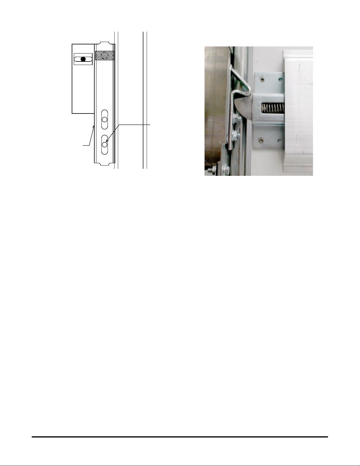
5. Reposition the latch plate so that the latch plate ts snugly against the latch (primary position for
a fan type).
6. Ensure that the latch plate is level and square with the latch and tighten the nuts.
7. After latches on both sides of the door are properly adjusted, cycle the door several times to
check proper engagement (primary position). Check that the latching and unlatching is smooth
and that the door seals at the bottom.
One-position latch
Utilimaster Customer Service
574-848-2200
Email: CustSvc@Utilimaster.com
Door Rear Roll-up, W-Series, July 2016
©Utilimaster Corp., 603 Earthway Boulevard, Bristol, Indiana 46507 USA
Square latch plate with latch (facing outboard)
BOLT IN STUD
BASE
LATCH PLATE
LEVEL
DOOR
TRACK
Table of contents
Popular Garage Door Opener manuals by other brands


Roger
Roger AYRON Series INSTRUCTIONS AND RECOMMENDATIONS FOR THE INSTALLER

Doco
Doco RES STF Manuals

EINHELL
EINHELL TAF 362 Mounting and operating instructions

Chamberlain
Chamberlain LM50 Assembly and operating instructions

Dormakaba
Dormakaba ED50 owner's manual

Beninca
Beninca DU.45E operating instructions


