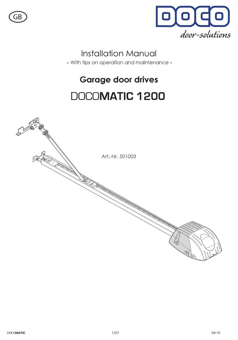
Doco RES STF User manual

Manual
Sectional door with front springs (RES STF)
Conform TÜV / CE EN 13241-1
©All rights reserved.
DOCO International BV
2006
EN

8-8-2006
Handleiding
EN STF V1.0 www.doco-international.com
2
Contents
1 Symbols and warning signs 3
2 General warnings 3
2.1 Safety instructions for assembly, commissioning and maintenance 3
2.2 Warranty and liability 3
3 Directives, applications and limitations 4
4Assembly 5
4.1 Preparingtheassembly 5
4.2 Mounting materials and instructions 6
4.3Tools 6
4.4Torques 7
4.5 Assembly instructions 8
5Electric operation (optional) 23
5.1 Adjusting the drive 23
6Commissioning 23
7Troubleshooting 23
8 Disassembly 24
8.1Removal 24
9Yoursupplier 24
Annex A Overview hardware and panel combination 25
Annex B Operators 25
Annex C Kits 26
Annex D Assembled galvanised spring sets 31
Annex E Panelhardware 32

8-8-2006
Handleiding
EN STF V1.0 www.doco-international.com
3
1. Symbols and warning signs
General symbol for DANGER!!
Symbol for ATTENTION!!
Carefully read the text with this symbol!!
Symbol: Risk of physical injury!!
Carefully read the text with this symbol!!
Use safety gloves Use Face protection
2. General warnings
This manual has been prepared for use by qualified personnel and therefore not by
trainees or “do it yourselfers”
In case of doubt about the assembly and/or maintenance, please contact DOCO
International.
To avoid severe personal injury, carefully read and observe all indications and warnings in this manual.
-This manual describes the assembly and disassembly of residential set of fittings ST ; this may be
supplemented by other manuals, for instance the door operator manual (if applicable.)
-Your set of fittings has been designed according to the latest European standards; however you have to
check yourself whether this standard corresponds with the local national standard.
-Adding or leaving out parts can affect the working and therefore the safety of the eventual sectional
door and is therefore strongly discouraged!
-All indications concerning the assembly the mounting right / left are always viewed from the assembly
location, that is from the inside to the outside!
-All measures are in millimetres unless otherwise specified.
-Check after the assembly whether the CE marking has been completed and attached.
-Keep this manual in a safe place.
-Subject to technical changes, without written notice.
2.1 Safety requirements for assembly and first use.
-The garage door may only be mounted, connected and put into operation by qualified personnel.
-Make sure that the power is switched off and remains switched off while electrical work is carried out!
-Never bridge safety devices !
-Some parts contain sharp edges: use protective gloves.
-Never use the sectional door in case or visual damage on the safety devices.
-When performing assembly/maintenance, always wear at least gloves and safety boots and during
drilling wear safety goggles!
-Make sure that you can always perform your work in a stable environment.
-Secure the assembly/maintenance site with safety ribbon to keep others (children!) at a distance.
-Maintenance must only be performed by a qualified company and/or qualified personnel.
-Make sure there is enough light.
-Only use appropriate tools, especially when tensioning the torsion springs.

8-8-2006
Handleiding
EN STF V1.0 www.doco-international.com
4
2.2 Guarantee and liability
Unprofessional assembly, any changes made to the garage door or changes in the door operator that do not
comply with this manual will annul the guarantee and liability.
This also applies to damage caused by incorrect operation, failure to observe the instructions in this manual
and/or poor maintenance or care.
3. Directives, applications and limitations
Doco garage doors comply with the following Directives:
•EMC Directive*
•LVD Directive*
•Machine Directive*
•CPD Directive*
(* E driven doors).
DOCO International developed this hardware set, which is intended for mounting in residential garages:
•Max. width 5000 mm
•Max height 2580 mm
•Weight door panel: max 162 kg
•Noise production: : <70 dBa
•Temperature range: –20º to + 40ºC
•Service-life 25,000 cycles
•CE approved according to SP certificate for use with the correct DOCO parts (see parts lists SET 1 to 4)
DOCO International had the “Product Test“ (ITT Initial Type testing) of this set of fittings carried out by the
institute SP in Sweden, known as Notified Body No. 0402.
Documents of this “ITT” are available from DOCO upon request.
The person or the company installing this door must thoroughly check if the door can be operated safely in
combination with the selected E-drive and panel, see “Product test report (ITT Report)”; Annex A and B.
This “ITT” does NOT include a pass door. If you want to install a pass door, a separate Product Test must be
carried out. This is the responsibility of the garage door manufacturer.
If parts are mounted that are not mentioned or if other parts are used that are not listed in this manual, the CE
certification will be invalid!

8-8-2006
Handleiding
EN STF V1.0 www.doco-international.com
5
7 Assembly
This set of fittings does not include the mounting material needed to mount this rail set on walls and/or the
ceiling! It is the responsibility of the installer to check whether the construction of the mounting place is strong
enough to support this garage door. The installer is also responsible for choosing the appropriate fixing materials
for the foundation (stone, concrete, steel, wood).
4.1. Preparation of the assembly
-Check if the place where you want to mount the rail set is level and if the construction of the mounting
place is strong enough to support this rail set. If not: reinforce
-Before you start the assembly, check if the garage has the required dimensions (figure 1).
W = Clear width
H = Clear height
OH = Upper space
Z = Lateral space
D = Built-in depth
System STF OH = 190
Angle Max Height (H) Z D ( 21182-L / 21226-L) D ( 21226-L / 21270-L) D ( 21270-L / 21340-L)
23699 2140 80 2600 3040 3480
23698 2580 80 3040 3480

8-8-2006
Handleiding
EN STF V1.0 www.doco-international.com
6
4.2 Mounting materials
4.3 Tools

8-8-2006
Handleiding
EN STF V1.0 www.doco-international.com
7
4.4 Toque instructions
Omschrijving Bevestigingsmateriaal Aantal Vastzetmoment (Nm)
Angle (23699/23698) with coverplate (24714) 14022 4x 20
14023 4x 20
Coverplate (24714)) with short horn (22979) 14022 4x 10
14023 4x 10
Curve (22301-L/22251-L) with angle (23699/23698) 14022 20x 20
14023 20x 20
J track (21182-L / 21226-L / 21270-L /21340-L) with connection plate
(24604) 14022 8x 20
14023 8x 20
J track (21182-L / 21226-L / 21270-L /21340-L) with connection plate
(24809) 14022 6x 20
14023 6x 20
J track (21182-L / 21226-L / 21270-L /21340-L) with short horn (22979) 14022 2x 10
14023 2x 10
J trackl (21182-L/21226-L/21270-L) with angle (24621) 14022 2x 20
14023 2x 20
Angle (24621) with mounting plate (24620) 14022 2x 20
14023 2x 20
End bearing plate (13022) and spring break device (25649…) 14022 4x 20
14023 4x 20
End bearing plate (13018 / 13022) and bearing supports (13026/27) 14022 4x 15
14023 4x 15
Spring break device (25649…) and spring plug (12002 S /12003 S) Moer 3/8" 4x 15
Spring break device (25649…) and ratchet wheel (25649….) Inbus 1/8" 4x 4.5
Spring plug (12002 W / 12003 W) and shaft (25018 / 25016) 14001 4x 34
Cable drum ( 11000 /11001 / 11014) and shaft (25018 / 25016) 14001 4x 34
Cable drum (11001 / 11014) and cable (25111-…) Bolt 3/8"-16UNC-1 1/4"
spec. 2x 18
Coupler (25042) with shaft (25016 /25018) / key (25064 / 25073) 14001 4x 34
Coupler (25042) between the two halves Bolt 3/8"-16UNC-1 3/4" 3 34
Nut nylon 3/8"-16UNC 3 34
Coupler (25034) and shaft (25016 /25018) / key (25064 / 25073) 14001 3x 34
Bottom bracket (25029) and panel 14017 12x 15
Side hinges and panel (per side hinge) 14017 6x 12
Roller carrier and basis side hinge (per hinge) 14022 2x 15
14023 2x 15
Intermediate hinges and panel (per intermediate hinge) 14017 4x 10
Top roller carrier (25046 / 25043) and panel 14017 4x 10
Top roller carrier (25046) and adjustable bracket (25046) 14022 2x 18
14023 2x 18

8-8-2006
Handleiding
EN STF V1.0 www.doco-international.com
8
4.5 Assembling instructions
1) Cut the verticale angle
View: right side.
2) Mount the steel cover plate (24714)
View: right side.
3) Mount the weatherstrip (24740)
View: right side.

8-8-2006
Handleiding
EN STF V1.0 www.doco-international.com
9
4) Position the vertical tracksets
- Floor not level? Fill up at position “3”!
- Height position verticale tracks = underside track, position 4.
5) Mount verticale track part agains the wall.
View: right side

8-8-2006
Handleiding
EN STF V1.0 www.doco-international.com
10
6) Mount the short horn, hand fix,
moveable!
View: right side

8-8-2006
Handleiding
EN STF V1.0 www.doco-international.com
11
7) Cut the curved track on the right dimension.
Vesion 2140 : L=2140-H+35
Version 2140 till 2580 : L=2580-H+35
View: right side
8) Mount the J track with curve.
Offset 25029 : 38 mm (with 40 mm panel)
Offset 25350 : 36 mm (with 40 mm panel)
View: right side

8-8-2006
Handleiding
EN STF V1.0 www.doco-international.com
12
9) Connecting horizontal J track.
View: right side
.
10) Put the connected J track into the verticale trackset part.
View: right side
11) Connect the track with the sleeve.
View: right side

8-8-2006
Handleiding
EN STF V1.0 www.doco-international.com
13
12) Put the short horn against the J track.
View: right side
13) Fasten the short horn with bolts and nuts.
View: right side

8-8-2006
Handleiding
EN STF V1.0 www.doco-international.com
14
14) Mount the suspension to the roof, to this Left and Richt
View: right side.

8-8-2006
Handleiding
EN STF V1.0 www.doco-international.com
15
15) Check following:
C=D
A=B
16) Mounting C-track (only if W= >3000 )
Detail: View: right side

8-8-2006
Handleiding
EN STF V1.0 www.doco-international.com
16
17) Mounting of the lintel sealing:
18) Mounting of the end brackets:

8-8-2006
Handleiding
EN STF V1.0 www.doco-international.com
17
19) Mounting the shaft and springs:
Use : seperate manual residential spring break device (25649-50 / 25649-67)
Doorsize : width < 3000 mm
Doorsize :width > 3000 mm <5000 mm
.
*

8-8-2006
Handleiding
EN STF V1.0 www.doco-international.com
18
20) Montage van de panelen:
General :
Hereby a general description for mounting the panels.
Always ask the manufacturer of your panel which additional measures, if any, are needed to guarantee the finger
guard Scharnieren voorboren met een Ø 4,5 mm boor ,echter raadpleeg uw paneel fabrikant voor de juist
voorboor maat! Generally, sandwich panels (steel plates with PUR foam) need pre-drilling with Ø 4.5 mm.
However always check with the manufacturer of your panels which exact size you need for pre-drilling!
The entire door blade including aluminium profiles and bottom seal must have the following dimensions.
.

8-8-2006
Handleiding
EN STF V1.0 www.doco-international.com
19
21) Voormontage bodemsectie:
Important: NEVER shorten the bottom panel to
determine the total height of the door blade; always
shorten the top panel!
Consult Annex: A to select the correct hinge and panel combination.
The distance between the central hinges must be distributed evenly over the panel length, see table 1. The
recommended maximum torque of the different parts is listed in table 2.
Tabel 1 Tabel 2
Deurbreedte
Aantal middenscharnieren
0-2749
2749-3999
3999-5000
1
2
3
-Saw the panel (1) to the right length.
-Mount the end caps (2) on the panel (1) using
blind rivets.
-Slide the aluminium profile (5) along the
entire length of the panel (1) and secure it
with blind rivets. Slide the sealing rubber on
the aluminium profile.
-Mount the bottom bracket 25029.
-Mount the side and intermediate hinges
Plaat schroef
Art. 14017 Aandraaimoment
Bodenkonsole
Zijscharnier
Middenscharnier
Toprolhouder
12 Nm
12 Nm
10 Nm
12 Nm

8-8-2006
Handleiding
EN STF V1.0 www.doco-international.com
20
22) Pre-mounting the intermediate sections :
.
23) Placing the panels:
Ensure that you do not forget spacer 25630! Otherwise there is a risk of
damaging the cable set.
-Slide the finger guards (25700) over the track roller body before
mounting the track rollers.
-Place the intermediate sections on the bottom sections and
connect them with the hinges. Adjust the nylon rollers in such a
way that the plastic tread lies in the rounding of the rail and that
the play between panel and side seal (24740) is reduced to a
minimum. You should be able to turn the plastic with your hand.
Table of contents
Other Doco Garage Door Opener manuals
Popular Garage Door Opener manuals by other brands

B&D
B&D Controll-A-Door 5 instruction manual

Chamberlain
Chamberlain WeatherDrive LM555EVGBSA Installation and operating instructions

Genie
Genie SC 1500 Operation & maintenance manual

Craftsman
Craftsman 139.53904D owner's manual

Chamberlain
Chamberlain MT5011U installation manual

Chamberlain
Chamberlain Security+ 1215EM FS2 owner's manual