Spartus 130XT User manual
130XT
230XT 330XT
930XT
User’s manual
WELDING HELMETS
430XT
©

WELDING EQUIPMENT SUITABLE FOR TODAY’S NEEDS
Thank you for purchasing our product!
You have made a right choice. Plasma welding and welding processes are
carried out in difficult conditions that expose welding equipment to extreme
tests of its strength. Only high quality equipment can ensure required reliability
and performance during realization of the above-mentioned processes. SPAR-
TUS® products are characterized by precisely such features: they are primarily
reliable and durable, but they are also versatile. We listen carefully to clients’
needs.Therefore, our offer covers such a wide assortment of products. Thank
you very much for your trust in our company. We would like to invite you to
familiarize yourself with the remaining products and offer at www.spartus.
info or directly at alocal distributor of SPARTUS® products.

Before using this product, read the instruction manual in its entirety, with understanding.
Keep the instructions for quick reference to it if necessary. Pay special attention to safety
instructions provided for your protection. In the event of any points of misunderstanding
instructions, contact your supplier or supervisor.
IMPORTANT!
TABLE OF CONTENTS
1. SAFE USE ....................................................................................................................................................................... 2
1.1 Welding arc radiation can be dangerous ......................................................................................................................... 2
1.2 Symbols used in instructions ................................................................................................................................................ 3
2.
CONFORMITY WITH STANDARDS ........................................................................................................... 3
3.
GENERAL DESCRIPTION ............................................................................................................................. 3
3.1 Purpose of use ............................................................................................................................................................................. 3
4.
TECHNICAL SPECIFICATIONS .................................................................................................................... 4
4.1 Operation, storage and transport ....................................................................................................................................... 4
4.2 Technical parameters of welding helmet ......................................................................................................................... 4
4.3 Used markings ............................................................................................................................................................................ 5
5.
OPERATION AND USE .................................................................................................................................. 6
5.1 Description of construction ................................................................................................................................................... 7
5.2 Using of welding helmet ....................................................................................................................................................... 11
6.
MAINTENANCE ........................................................................................................................................... 12
6.1 Replacing the lters covers .................................................................................................................................................. 13
6.2 Battery changing ...................................................................................................................................................................... 13
6.3 Cleaning instructions ............................................................................................................................................................. 13
7.
LIST OF SPARE PARTS FOR HELMETS .................................................................................................. 14
8.
ENVIRONMENTAL PROTECTION ........................................................................................................... 15
9.
TROUBLESHOOTING ................................................................................................................................. 15

USER’S MANUAL EN
2
1. SAFE USE
Arc welding and plasma cutting are processes that can pose hazards for the operator and persons
in his vicinity. The operator and his close surroundings are exposed, among others, to the risk
of fire, explosion, electric shock, burning, as well as the risk of getting injured by moving parts
of the device.
Once proper safety measures are provided, electric welding and plasma cutting are relatively
safe processes. For this reason, it is crucial to strictly follow the valid OSH principles during
welding operations.
The information provided below does not release the operator from the obligation to follow
the OSH rules that are binding in his plant/workplace.
Only professionally trained and qualified personnel may install, operate, maintain and repair
the device.
For operators and their supervisors training is essential in: the safe use of the equipment; the
processes; the emergency procedures.
1.1 WELDING ARC RADIATION CAN BE DANGEROUS
In order for maximum user safety we would like to remind the rules limiting the risks arising
from radiation emitted by the welding arc.
Spawanie łukowe i cięcie plazmowe to procesy, które mogą stwarzać zagrożenie dla operatora
i osób znajdujących się w pobliżu. Operator i jego najbliższe otoczenie wystawieni są między
innymi na ryzyko zagrożenia pożarem, wybuchem, porażenia prądem, oparzenia, a także
ryzyko poniesienia obrażeń w wyniku kontaktu z częściami ruchomymi urządzenia. Po
zapewnieniu odpowiednich środków ochronnych, spawanie elektryczne i cięcie plazmowe
to procesy stosunkowo bezpieczne. Z uwagi na to, kluczowe podczas przeprowadzania prac
spawalniczych jest bezwzględne stosowanie się do panujących zasad BHP. Poniższe informacje,
nie zwalniają operatora z obowiązku przestrzegania zasad BHP obowiązujących w zakładzie
Przy wykonywaniu prac spawalniczych, należy stosować się również do wymagań BHP
zawartych w aktualnych wersjach aktów prawnych, do których należą między innymi:
• Rozporządzenie Ministra Infrastruktury z dnia 6 lutego 2003 r. w sprawie bezpieczeństwa
i higieny pracy podczas wykonywania robót budowlanych (Dz. U. 2003, Nr 47, poz. 401) -
Rozdział 16
• Rozporządzenie Ministra Gospodarki z dnia 27 kwietnia 2000 r. w sprawie bezpieczeństwa i
higieny pracy przy pracach spawalniczych. (Dz. U. z 2000 r. Nr 40, poz. 470)
• Rozporządzenie Ministra Gospodarki, Pracy i Polityki Społecznej z dnia 23 grudnia 2003 w
sprawie bezpieczeństwa i higieny pracy przy produkcji i magazynowaniu gazów, napełnianiu
zbiorników gazami oraz używaniu i magazynowaniu karbidu (Dz. U. 2004 nr 7 poz. 59)
• Rozporządzenie Ministra Spraw Wewnętrznych i Administracji z dnia 7 czerwca 2010 r. w
sprawie ochrony przeciwpożarowej budynków, innych obiektów budowlanych i terenów (Dz.
U. 2010 nr 109 poz. 719)
• oraz wszelkich nowych rozporządzeń.
Tylko profesjonalnie przeszkolony i wykwalikowany personel może zainstalować, obsługiwać,
konserwować i naprawiać urządzenie. Dla operatorów (użytkowników) i ich przełożonych
niezbędne jest posiadanie odpowiednich szkoleń i kwalikacji: z zakresu bezpiecznego
użytkowania sprzętu; nt. prowadzonych procesów; nt. procedur awaryjnych.
1.1. PROMIENIOWANIE ŁUKU MOŻE BYĆ NIEBEZPIECZNE
W trosce o jak największe bezpieczeństwo użytkowników, przypominamy zasady ograniczenia
zagrożeń wynikających z emitowanego promieniowania przez łuk spawalniczy.
Łuk spawalniczy generuje:
• Promieniowanie ultraoletowe (może uszkodzić skórę i oczy)
• Światło widzialne (może oślepić oczy i upośledzić widzenie)
• Promieniowanie podczerwone (może uszkodzić skórę i oczy)
Promieniowanie łuku spawalniczego może oddziaływać bezpośrednio lub być
odbite od gładkich powierzchni metalowych lub kolorowych przedmiotów.
1. BEZPIECZEŃSTWO UŻYTKOWANIA
3
INSTRUKCJA OBSŁUGI * PRZYŁBICA SPARTUS
PL
The arc generates:
• ultraviolet radiation (can damage skin and eyes),
• visible light (can dazzle eyes and impair vision),
• infrared (heat) radiation (can damage skin and eyes).
Such radiation can be direct or reflected from surfaces such as bright metals and light
coloured objects.
1.1.1 Eye and face protection
• Use welder’s helmet/shield with an appropriate filter to protect you face and eyes against
sparks and welding arc radiation.
• Welding helmet/shield should prevent injuries from flying particles, e.g. slag, fragments
from grinding or wire bristles, etc.
• Welding helmet/shield should be made in accordance with applicable standards.
1.1.2. Body protection
• The body should be protected by suitable clothing in accordance
with applicable standards.
• Use appropriate protective clothing made of durable and fire-resistant material,
to ensure proper skin protection.
• The use of neck protection can be necessary against reflected radiation.

USER’S MANUAL
EN
3
1.1.3. Protection of persons in the vicinity of an arc
• Protect the remaining personnel present in the vicinity of welding works against negative
impact of arc radiation and welding splatters. Warn them about the hazard resulting from
exposure to the welding arc.
• In the vicinity of an arc, non-reflective curtains or screens should be used to isolate
persons from the arc radiation. A warning, e.g. a symbol for eye protection, should refer
to the hazard of arc optical radiation.
• Welder’s assistants should also wear appropriate protective clothing.
1.2. SYMBOLS USED IN INSTRUCTIONS
We use those symbols to pay your attention about important informations.
2. CONFORMITY WITH STANDARDS
The SPARTUS®welding helmets are in conformity with the relevant Union harmonization legislation:
Directive 2016/425/UE PPE Personal protective equipment
and that the following harmonized standards applied:
EN 175 Personal protection. Equipment for eye and face protection
during welding and allied processes
EN 379 Personal eye-protection. Automatic welding filters
CE marking was placed on the product.
3. GENERAL DESCRIPTION
SPARTUS®helmets have been designed to protect welder’s eyes and face against the harmful
radiation and weld spatters during welding: TIG, MIG/MAG, MMA. Additionally devices have
afunction of grinding.
SPARTUS®helmets are equipped with automatic welding filter with manual protection level
adjustment. Built-in 4 sensors ensures maximum filter sensitivity. Filter includes possibility of
regulation: filter darkening grade, time of filter brightening and filter sensitivity. The preview
of the view is presented in real colors (true color).
Helmets are made of tough polyamide (Nylon). Adjusted headband enables easy adaptation
to welder’s needs.
3.1 PURPOSE OF USE
Automatic welding helmets SPARTUS® are designed to protect the face and eyes of the welder,
against sparks and welding spatter and against harmful radiation which arises under normal
conditions when:
• GMAW gas metal arc welding (MIG/MAG)
• Tungsten inert gas welding (TIG)
• Manual metal arc welding (MMA) (SMAW – shielded metal arc welding)
SPARTUS® welding helmets can be also used to protect face and eyes during grinding elements
made of metal.

USER’S MANUAL EN
4
It is forbidden to use the SPARTUS® helmet for eye and face protection during welding
and gas cutting, welding and laser cutting. The welding helmet does not protect against
explosive devices or corrosive liquids. It is forbidden to use misused.
4. TECHNICAL SPECIFICATIONS
4.1 OPERATION, STORAGE AND TRANSPORT
Conditions during operation, storage and transport
Range of ambient air temperature during operation from -5°C to +50°C
Range of ambient air temperature during storage and transport from -20°C to +70°C
Store and transport packaging protects against mechanical damage to the helmet.
Do not store or transport, when external and internal covers are taken off.
4.2 TECHNICAL PARAMETERS OF WELDING HELMET
Easy
130XT
Master
230XT
Pro
330XT 430XT 930XT
Application arc welding: MMA, TIG, MIG/MAG and grinding
WELDING FILTER PARAMETERS
Type of welding filter automatic with manual adjustment degree of protection
true color
Number of sensors 4
Active field of view [mm] 98 x 55 100 x 65 100 x 73 100 x 65
Filter size [mm] 110 x 90 x 9 122 x 125 x 9
Shading (standby) DIN 4 DIN 3.5
Variable welding shades
(operating) DIN 9 – 13 DIN 4 – 8 or DIN 9 – 13
UV/IR protection degree to DIN 16
Light to dark switching time [s] 1/25 000 1/30 000
Delay control light
to dark switching time [s] 0.25 – 0.8 0.3 – 0.9 0.25 – 0.85 0.2 – 1.0
Sensitivity infinitely adjustable
Power supply solar cells and lithium battery
Optical class 1
Diffusion of light class 1
Variations in Luminous
transmittance class 1
Angle dependency class 2 1
Test function
Grinding mode

USER’S MANUAL
EN
5
OTHER
Helmet shell material poliamid (PA, Nylon)
Mechanical resistance B acc. EN 175
Headgear adjustable
Weight [g] 520 480 490 500 540
Adjustment knob and switch external internal external
4.3 USED MARKINGS
4.3.1 Welding filter SPARTUS®Easy 130XT
Marking: 4/9-13 ART 1/1/1/2 EN 379
4 Light shade
/9 The lightest shade
-13 The darkest shade
ART Identication
1 Optical class
/1 Diusion of light class
/1 Variations in Luminous transmittance class
/2 Angle dependency class
EN 379 Number of standard
4.3.2 Welding filter SPARTUS® Master 230XT
Marking: 4/4-8/9-13 ART 1/1/1/1 EN 379
4 Light shade
/4 The lightest shade (range I)
-8 The darkest shade (range I)
/9 The lightest shade (range II)
-13 The darkest shade (range II)
ART Identication
1 Optical class
/1 Diusion of light class
/1 Variations in Luminous transmittance class
/1 Angle dependency class
EN 379 Number of standard

USER’S MANUAL EN
6
4.3.3 Welding filter SPARTUS® Pro 330XT
Marking: 4/4-8/9-13 ART 1/1/1/1 EN 379
4 Light shade
/4 The lightest shade (range I)
-8 The darkest shade (range I)
/9 The lightest shade (range II)
-13 The darkest shade (range II)
ART Identication
1 Optical class
/1 Diusion of light class
/1 Variations in Luminous transmittance class
/1 Angle dependency class
EN 379 Number of standard
4.3.4 Welding filter SPARTUS® Pro 430XT
Marking: 3/4-8/9-13 ART 1/1/1/1 EN 379
3 Light shade
/4 The lightest shade (range I)
-8 The darkest shade (range I)
/9 The lightest shade (range II)
-13 The darkest shade (range II)
ART Identication
1 Optical class
/1 Diusion of light class
/1 Variations in Luminous transmittance class
/1 Angle dependency class
EN 379 Number of standard
4.3.5 Welding filter SPARTUS® Pro 930XT
Marking: 3/4-8/9-13 ART 1/1/1/1 EN 379
3 Light shade
/4 The lightest shade (range I)
-8 The darkest shade (range I)
/9 The lightest shade (range II)
-13 The darkest shade (range II)
ART Identication
1 Optical class
/1 Diusion of light class
/1 Variations in Luminous transmittance class
/1 Angle dependency class
EN 379 Number of standard

USER’S MANUAL
EN
7
4.3.6 Helmet shell SPARTUS®
Marking: EN 175 B
EN 175 Number of standard
B Mechanical resistance: medium Energy impact
5. OPERATION AND USE
WARNING!
SPARTUS®welding helmet is intended for professional and industrial applications. Installation
and use of the device may only be carried out appropriately trained professionals.
Qualified person (def.)
A person who has gained the relevant technical education, training took place and / or gained
experience to perceive the risk and avoid hazards during use of the product (IEC 60204-1). (IEC 60204-1).
5.1 DESCRIPTION OF CONSTRUCTION
WARNING!
It is forbidden to make any unauthorized modifications to the welding filter and / or other
components of a SPARTUS® welding helmet.
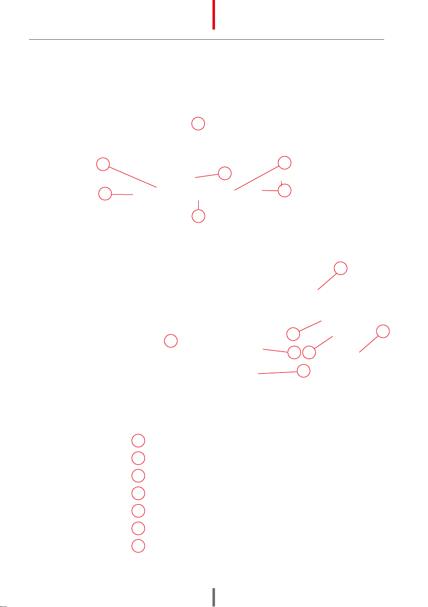
5.1.1 Automatic welding filter
SPARTUS®Easy 130XT
1
2
4
5
3
SPARTUS®Master 230XT
1
2
3
4
5
6
USER’S MANUAL EN
8
1Welding/grinding switch
2Shade adjustment knob
3Delay time adjustment knob
4Sensitivity adjustment knob
5Test button
6Battery socket CR2450 3V
7Inner polycarbonate lter shield
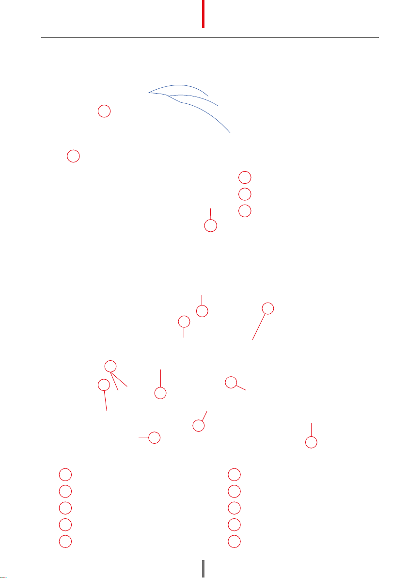
SPARTUS®Pro 930XT
7
1
2
3
5
6
4
SPARTUS®Pro 330XT / Pro 430XT
10
7
1
23
5
6
4
USER’S MANUAL
EN
9
8Welding helmet shell
9Outer polycarbonate lter shield
10 Screw nuts (headgear)
8
9
10
5.1.2 Welding helmet SPARTUS®
5.1.3 Headband of SPARTUS® helmet
11 Sweatband (cloth)
12 Headband top pad
13 Front headband
14 Headband back pad
15 Headband regulator assembly
19
18
17
16
14
15
20
12 13
11
16 Left band & right band
17 Angle adjusting shim (left/right)
18 Headband xing screw (left/right)
19 Headband rack (left/right)
20 Adjusting the distance of the visor
USER’S MANUAL EN
10
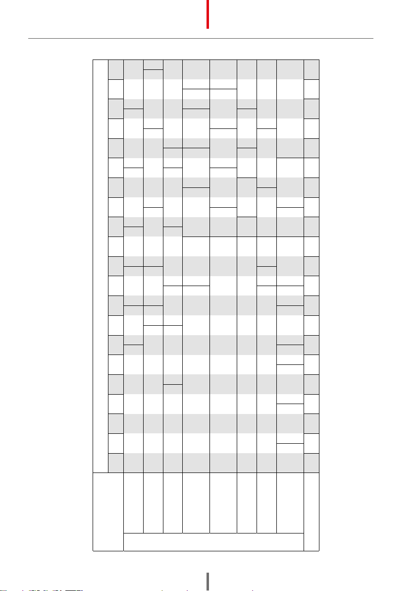
RECOMMENDED SHADING
* prepared by SPARTUS®according to EN 379
** term „heavy metals“ applies to steel, steel alloys, copper, copper alloys, etc.
Current [A]
1,5 6 10 15 30 40 60 70 100 125 150 175 200 225 250 300 350 400 450 500 600
Level of security* for the process:
MMA 8 9 10 11 12 13 14
MAG 8 9 10 11 12 13
14
TIG 8 9 10 11 12 13 14
MIG
heavy metals** 9 10 11 12 13 14
MIG
light alloys 10 11 12 13 14
electroerosion 10 11 12 13 14 15
plasma cutting 9 10 11 12 13
microplasma
welding 4 5 6 7 8 9 10 11 12
1,5 6 10 15 30 40 60 70 100 125 150 175 200 225 250 300 350 400 450 500 600

USER’S MANUAL
EN
11
5.2 USING OF SPARTUS® WELDING HELMET
WARNING!
Scratched or damaged protection shields (inner and outer) have to be replaced for the
new one. Optical sensors must be kept clean. Remember to do not cover them.
Before first use
(or first use after a short break at work) of welding helmet you should check its technical
condition and operation of the welding filter by using the „TEST” button
5
. NextYou
should check that the shading degree
2
is correct to work carried out and the
corresponding mode is enabled operation
1
.
It is forbidden to weld, when theswitch
1
is in „GRIND”position.
5.2.1 Working principle (concerns welding filter)
Automatic welding filter switches automatically from light state to dark state upon the welding
arc ignition. In light mode the protection degree equals DIN 3.5 to DIN 4. The protection degree
in dark mode (when exposed to welding arc) equals DIN 4 to DIN 8 or DIN 9 to DIN 13. DIN value
in dark mode could be selected manually by the welder. Switching from dark state to light state
becomes after welding arc expires.
5.2.2 Selecting and adjusting the protection degree
To select and adjust shade number you should use the knob
2
. The user can choose between
values DIN 4 to DIN 8 or DIN 9 to DIN 13, depending on the selected knob 1position :
– for Easy 130XT model
a) 9 – 13
– for Master 230XT, Pro 430XT, Pro 930XT models
a) 4 – 8
b) 9 – 13
5.2.3 Sensitivity and delay adjustment
The sensitivity of the filter is responsible for the welding filter response to changes in light.
Before each use, set its value to the maximum. In the sunny rooms or when are multiple light
sources may be necessary to reduce the sensitivity of the filter.
The highest sensitivity: knob 4SENSITIVITY: HIGH.
Delay time is to which when filter passes from the dark state to the light state DIN 4. It is
recommended to set this value to maximum.
The maximum delay time: knob 3DELAY: LONG.
5.2.4 Adjusting headgear
Too loose headgear can cause an excessive down slope of the
welding helmet. When headgear is too tight can cause excessive
pressure on head and consequently causes to discomfort. To
adjust the right size of headband (loose or tighten) use the
adjustment knob 15 .
The headgear should not fall too much on the operator’s face.
The helmet depth is adjusted using the top strap 12 .

USER’S MANUAL EN
12
5.2.5 Adjusting the distance between face and helmet
If the distance between the welder’s face and the helmet body is too small, change the distance
settings. Headgear has 3 levels of distance regulation. To set right distance from the face use
the mechanizm
20
.Release pin and set the right distance level. Remember that it has to be
simetrical regulated on both sides of headgear.
5.2.6 Incline angle adjustment
An inappropriate angle of inclination may cause discomfort during operation or cause the visor
to move over the head of the operator when tilting the head.
Incline angle adjustment can be made by using angle adjusting shim 17 in to both sides.
5.2.7 Automatic welding filter lifting system
SPARTUS® Pro 930XT helmet has been
designed and equipped with a special
mechanism for raising and lowering the
welding filter. When lifted, the helmet’s
center of gravity is lower and coincides with
the head’s center ofgravity.This reduces the
welder’s neck tiredness and significantly
increases his comfort of work. The field of
view also increases – 165x72mm, and the
welder’s eyes are protected by aprotective
glass.
Warning! The lever should be adjusted simultaneously with two hands – up (when lifting) and down (when
lowering).
5.2.8 Turning on the grind mode
SPARTUS®helmets have a grinding function. To enable the grinding function, set the switch
1
into GRIND position. The degree of protection for the grinding function is DIN 4.
In SPARTUS® Pro 930XT model it is also possible to lift the automatic welding filter with special
levers. We get a larger field of view – 165x72mm, while maintaining eye protection through an
external protective glass.
6. MAINTENANCE
Maintenance and repair work may be performed only by qualified personnel with the appropriate
permissions. Regular maintenance provides adequate service life and trouble-free operation of the
welding helmet.
Daily: (before use/installation):
• Perform visual inspection of the helmet, knobs, welding filter.
• Check for proper operation of welding filter using TEST button 5.
• Visually inspect the technical condition of the outer guard and the inner guard. Worn or
damaged covers should be replaced by a new one.
• Visually inspect the technical condition of the optical sensors.

USER’S MANUAL
EN
13
At least once a month:
• Visually inspect the sweatband. When worn replace by a new one.
Once a year:
• You should send welding helmet to an authorized service center for an interim review.
• Replace the battery that powers the welding filter.
6.1 REPLACING THE FILTERS COVERS
Regular replacement of the filter welding shield is needed to do the correct operation of the
helmet. Excessively worn or damaged filter covers must be replaced by a new one.
6.1.1 Replacing outer filter cover
Step 1: Carefully remove the filter cartridge. In order to remove the cartridge from the welding
filter gently loosen the locking tabs.
Step 2: Replace protective plate for the new one.
Step 3: Place the filter cassette in welding helmet, and then lock the latch.
x
z
6.1.2 Replacement of the internal protective glass
Step 1: Unlock the latch on both sides of the glass x, z.
Step 2: Remove the used protective glass.
Step 3 : Install a brand new protective glass by pushing it into the
appropriate latches on both sides of the helmet.
6.2 CHANGING BATTERY IN THE HELMET
Use lithium batteries CR2450 3V.
6.3 CLEANING INSTRUCTIONS
Clean the welding filter and protection/cover plates with lint-free tissue or cloth. Do not immerse
in water or spray directly with liquids.

USER’S MANUAL EN
14
A
E
D
B
F
C
D
A
B
D
D
AHelmet shell
BAuto darkening lter
CComplete headband
DHeadband knob
EFront cover lens
FInside cover lens
7. LIST OF SPARE PARTS OF HELMETS
WARNING!
Use only original parts of the helmet, supplied by an authorized retailer or an authorized service.
Unauthorized modifications and spare parts can expose the user to the risk of injury.

USER’S MANUAL
EN
15
8. ENVIRONMENTAL PROTECTION
The product must not be disposed of into an ordinary waste container. It is totally
forbidden to dispose of electric or electronic equipment marked with a crossed-
out trash can symbol by throwing it into ordinary waste containers. According
to the WEEE directive (directive 2012/19/UE), binding within the European Union,
such products should be disposed of according to local regulations.
We hereby inform the client that, according to the regulations, each commodity is burdened
with waste disposal costs (WDC) according to charging rates valid for a given year.
9. TROUBLESHOOTING
Problems with the operation of the device, are not always an evidence of its failure. You can independently
carry out an analysis in search of probable failure. In case of doubt, please contact to SPARTUS® dealer or
authorized service center.
During the warranty period all repairs should be carried by authorized service center. Repairs carried
out by unauthorized persons will void the warranty.
HELMET
Filter cannot darkening or ashes
Damaged or dirty front protection plate
Dirty optic sensors
Damaged automatic lter
Worn battery
Too low sensitivity (see 5.2.3)
Poor visibility Damaged or dirty front/inner protection plate
Incorrect setting of the degree of protection (see 5.2.2)
Slow lter reaction Too low ambient temperature
Worn battery
The helmet falls from the head Incorrect adjustment of headgear

Notes
07.2021

Simple solutions and an attractive price – these are
the features of SPARTUS® Easy series devices. Our
equipment has been designed with ease of use and
ergonomics at work in mind.
A masterly combination of high quality production,
excellent parameters and ergonomics – these are fea-
tures of the SPARTUS® Master series of devices, which
were created with demanding welding jobs in mind.
Precision, functionality, excellent parameters and
resistance to high workloads – these are the features
of the SPARTUS® Pro industrial series of devices. This
series consists of specialised solutions which will
satisfy even the most demanding users.

Videopresentation of products
Subscribe to the channel SPARTUS.INFO
This manual suits for next models
4
Table of contents
Other Spartus Welding Accessories manuals

Popular Welding Accessories manuals by other brands

Lincoln Electric
Lincoln Electric LN-7 Operator's manual

Chicago Electric
Chicago Electric 46092 Owner's manual & safety instructions

Telwin
Telwin TW3000 manual

FRONIUS
FRONIUS TransSynergic 4000 operating instructions

Abicor Binzel
Abicor Binzel ABITIG Little 24G Original operating instructions

Jegs
Jegs 81544 installation instructions

Parkside
Parkside PSHL 2 D1 Operation and safety notes

Miller
Miller 5 TURNTABLE owner's manual

Rossi
Rossi 255318 Assembly guide

Miller Electric
Miller Electric XR A owner's manual

Bohler
Bohler GUARDIAN 62F instructions

Harbor Freight Tools
Harbor Freight Tools CHICAGO ELECTRIC 46092 Owner's manual & safety instructions


