Spearhead Multi-Cut 420 User manual

Spearhead Multi-Cut 420
1
Spearhead
Multi-Cut 420
Handbook
1st Edition – April 2007
Important Note
The information contained in this manual is correct at the time of publication.
However, in the course of constant development, changes in specification are
inevitable. Should you find the information given in this book different to the
machine it relates to please contact the “After Sales Department” for advice.
© Spearhead Machinery Limited 2007
Please ensure that this manual is handed to the operator before using the
machine for the first time. The operator must fully understand the contents
of this manual before using this machine.
(
If the machine is resold the Manual must be
g
iven to the new owner.
)
Spearhead Machinery
Green View
Salford Priors
Evesham
Worcestershire
WR11 8SW
Tel: 01789 491860
Fax: 01789 778683
www.spearheadmachinery.com

Spearhead Multi-Cut 420
2
EC Declaration of Conformity,
Conforming to EEC Directive
89/392/EEC, 98/37/EC & 98/38/EC
We, Spearhead Machinery Ltd, Green View, Salford Priors, Evesham,
Worcestershire, WR11 8SW declare under our sole responsibility that the :
Product ……………………………………………………………
Product Code ……………………………………………………………
Serial No ……………………………………………………………
Flail Head Serial No ……………………………………………………………
Type ……………………………………………………………
Manufactured by the above company complies with the required provisions
of the directive 89/392/EEC, 98/37/EC and 98/38/EC and AMD
91/368/EEC, AMD 93/44/EEC, AMD 93/68/EEC and conforms with
European norm. BSEN 292; Part 1: 1991 Safety of Machinery – Technical,
Methodology; Part 2: 1991 Safety of Machinery - Technical Specifications
and other national standards associated with its design and construction
as listed in the Technical File.
Signed………………………………………………………………………………………..
(On behalf of Spearhead Machinery Ltd)
Status General Manager
Date.....................................

Spearhead Multi-Cut 420
3
Contents
Contents 3
Safety 4
Recommendations 5
Introduction 7
Tractor Requirements 7
Attaching to the Tractor 7/8
Setting up your Machine 9
Operation 10
Transportation 11
Machine protection 12
Servicing & Maintenance
SafetyFirst 13
Daily 14
Every 8 Hours 15
Torque Settings 15
Regularly 16
Blades 16
SlipClutchSettings 17
Skids 18
Wheels 18
Storage 19
Trouble Shooting Guide 20
Warranty 21

Spearhead Multi-Cut 420
4
Safety
Warning
Avoid fluid escaping
under pressure. Consult
technical manual for
services procedures.
Warning
Danger – flying objects
keep safe distance from
the machine as long as
the engine is running.
Warning
Stay clear of mower blade
as long as engine is
running.
Warning
Stay clear of swinging
area of implements.
Warning
Shut off engine and remove
key before performing
maintenance or repair work.
Warning
Check all nuts are tight
every 8 hours.
Warning
Carefully read operator’s
manual before handling this
machine. Observe
instructions and safety rules
when operating.

Spearhead Multi-Cut 420
5
Recommendations
Beware of the following Potential Dangers associated with the use of
this machine:
Becoming trapped when hitching or unhitching
Machine overbalancing when wing is raised.
Getting caught on rotating power take off (PTO)
Being hit or caught by any moving part, e.g. Blades, drive shaft and wings.
Being hit by flying debris or machine parts due to machine damage
Machine overbalancing when not in use
Injection of high pressure oil from damaged couplings or hydraulic hoses
Accidents due to collision with other machines, or debris left on road
Beware of free-swinging blades over centering and falling when wings are
folding.
ALWAYS:
Ensure the operator has read this handbook and has been trained to use the
machine.
Ensure all safety guards are in place and all tractor windows closed.
Impact resistant shielding to the tractor is recommended
Before leaving the tractor cab always ensure that the wings are firmly on the
ground, no weight is on the machine’s hydraulics and the rotor has stopped
spinning.
Check that all guards are properly fitted and there are no damaged or loose
parts. Particular attention should be given to the blades to ensure they are not
damaged, cracked or missing.
Inspect work area for wire, steel posts, large stones and other dangerous
materials and remove before starting work.
Ensure that all warning labels are always visible and that they are not
damaged, defaced or missing.
Fit locking bars to height and to wings before transport and before unhitching
when applicable.
Wear ear defenders if operating without a quiet cab or with the cab windows
open
Ensure tractor guards are fitted correctly and are undamaged
Work at a safe speed, taking into account terrain, passing vehicles and
obstacles
Ensure that the tractor meets the minimum weight recommendations of the
machine manufacturer and that ballast is used if necessary
Check that machine fittings and couplings are in good condition
Follow the manufacturer’s instructions for attachment and removal of machine
from the tractor
Ensure blades are of the type recommended by the manufacturer, are
securely fitted and are undamaged
Ensure hydraulic pipes are correctly routed to avoid damage from chafing,
stretching, pinching or kinking.
Check condition of tyres and tightness of wheel nuts.
Ensure all blades have stopped spinning before folding wings into transport
position.

Spearhead Multi-Cut 420
6
Disengage the machine, stop the engine and remove the key before leaving
the tractor cab for any reason
Clean up any debris left at the work site.
Ensure that when you remove the machine from the tractor it is secured in a
safe position using the stands provided, on level concrete base.
NEVER:
Never operate the machine with other people present, as it is possible for
debris, including stones, to be discharged from the front and rear.
Never operate the machine until you have read and understood this
handbook and are familiar with the controls.
Never use a machine that is poorly maintained or has guards that are
damaged or missing
Never allow an inexperienced person to operate the machine without
supervision.
Never use or fit a machine onto a tractor if it doesn’t meet the
manufacturer’s specification.
Never use a machine if the hydraulic system shows signs of damage.
Never attempt to detect a hydraulic leak with your hand, use a piece of
card.
Never allow children to play on or around the machine at any time.
Never attempt any maintenance or adjustment without first disengaging
the PTO, lowering the wings to the ground, stopping the tractor engine
and applying the tractor parking brake.
Never leave the cab without removing the ignition key.
Never operate the tractor or any controls from any position other than
from the driving seat.
Never stop the engine with the PTO engaged.
Never operate with blades missing.
Never operate PTO above recommended speed, 1000 r.p.m.
Never operate with wire around the rotor. Stop immediately.
Never use the wing raised which may throw debris towards the cab.
Never attempt to use the machine for any purpose other than that it was
designed for.
Never transport with the PTO engaged.
Never enter the working area of the machine (risk of injury!).
Never engage the P.T.O with wings folded.

Spearhead Multi-Cut 420
7
Introduction
The Spearhead 420 is a heavy-duty rotary mower for a set-aside, stubble and
pasture topping. By carefully following the instructions in this handbook, the 420 will
give many years of trouble free operation.
Safety First
Never start using the machine until the handbook has been read and understood.
The 420 rotary mower is a potentially lethal machine if used incorrectly and it is
essential that the operator fully understand the working before starting up.
Tractor Requirements
Spearhead recommend tractors of between 85 and 120hp.
Category 2 three-point linkage.
Stabilisers or check chains must be in good working order to hold the
machine firmly. Do not operate without ensuring the check chains or
stabilisers are tight. Spearhead particularly recommend “turnbuckle” type
check chains.
Set tractor lift rods of equal length.
Before hitching, ensure position control is selected. Do not attempt to hitch in
draft control.
Ensure there is sufficient weight on front wheels of the tractor for safe
transport and stability. The tractor should have a minimum weight of 3700 kg.
The tractor should have a 1000rpm P.T.O.
One external hydraulic service required, single acting with float facility for
wings.
Attaching To The Tractor
Fit the machine to the tractor in the standard way, ensuring the correct match of
linkage (category 2). Check that the top link is in good order and the threads are well
lubricated. Use stabilisers to eliminate any sideways sway.
Before lifting the machine with the tractor linkage you should ensure there is
sufficient front weight to keep the front wheels in contact with ground. This is most
important for safe transport and stability when turning on sloping ground.
It is essential to ensure that the tractor drawbar cannot foul the P.T.O. shaft, we
advise to remove it altogether if there is any doubt.
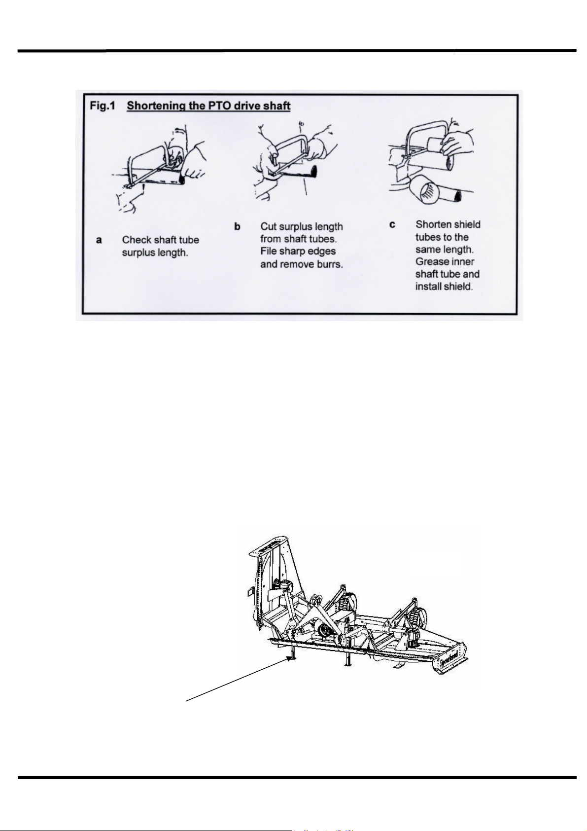
Before fitting the PTO for the first time, it may be necessary to adjust the length.
There should be maximum engagement of the sliding tubes without bottoming at the
shortest operation position. To check, first connect the mower to the tractor. Pull the
PTO shaft apart and connect to the tractor PTO output shaft and the gearbox input
shaft. Hold the half shafts next to each other in the shortest working position. If
necessary, shorten the inner and outer guard tubes equally (Fig. 1). Shorten the
inner and outer sliding profiles by the same length as the guard tubes. File all sharp
edges and remove burrs. Grease sliding profiles.
Spearhead Multi-Cut 420
8
Before fitting the PTO, first clean and grease. Remove the clamp bolts on the yoke
and slide onto the machine gearbox, refit the bolts into the grove tighten 150Nm. Pull
back the PTO release ring and slide onto tractor stub shaft until it engages.
The PTO shaft is fitted with a non-rotating safety guard. It should be secured to the
machine and tractor with the two retaining chains provided.
Connect the hydraulic hose, to a single acting service, with a dump facility. This is
important so the wings can follow the ground contours in work.
Connect the top link and adjust to ensure there is some slack in the wire ropes,
before raising the machine.
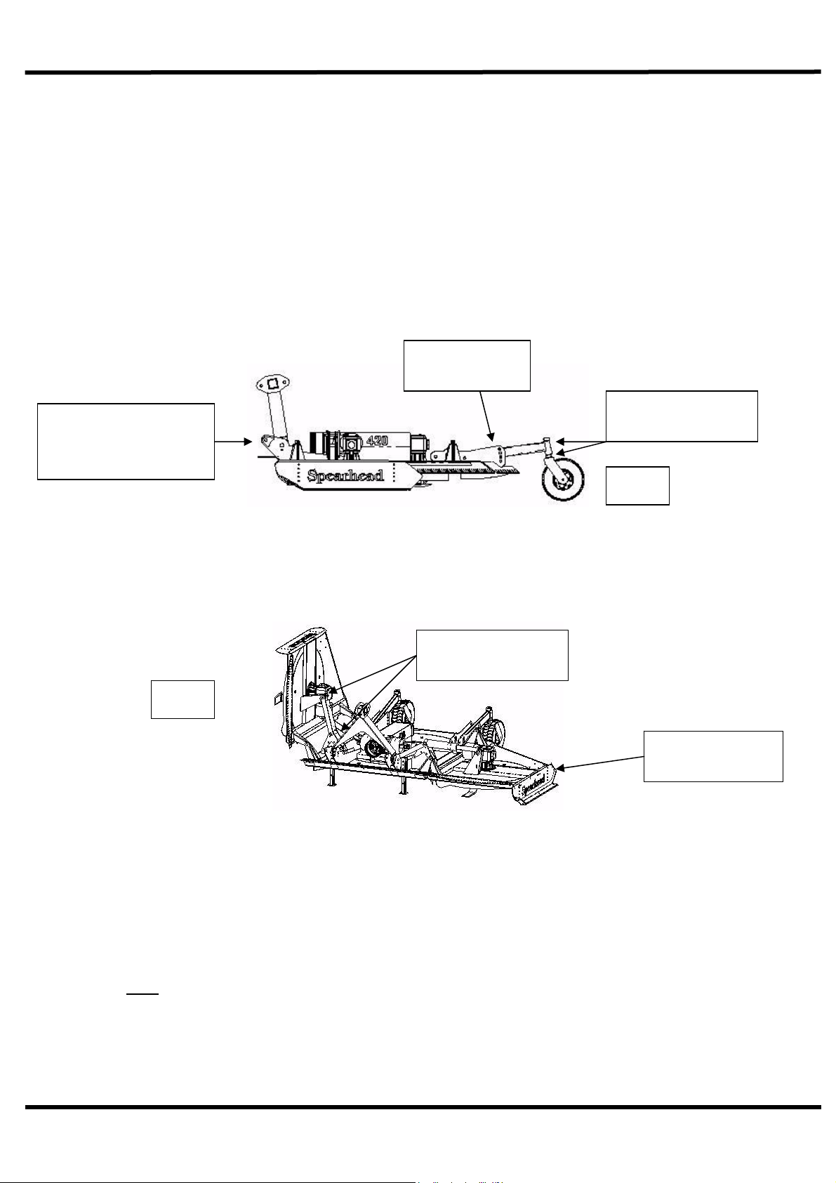
Raise the parking stands and secure locking pin.
Parking
stands
Fig 2
Spearhead Multi-Cut 420
9
Setting Up Your Machine
Height
To alter the height of cut; raise the machine so the wheels are clear of the ground,
remove pin a (Fig. 3) adjust the wheel arm, replace pin a (Fig 3) and gently lower the
machine until the wheel contacts the ground. Fine adjustment can be made by
moving the spacers on the wheel fork above or below the wheel arm, spacer b(Fig
3). Now adjust the height of the tractor link arms so the front of the mower is 25mm
(1”) higher at the front c.
The top link must be adjusted to ensure the wire ropes are slack, so the machine can
follow undulating ground fore and aft, but still allow the machine to lift when the
tractor link arms are fully raised.
Wings
Unfolding the wings if the machine is in the transport position, first pressurise
hydraulic rams before releasing locking bar (Fig 4), lower both wings by releasing
hydraulic pressure, leaving tractor spool in float position (Fig, 5).
Levelling the wing cutting height LH & RH
With the wings lowered, adjustable skids alter cutting height, these should be set to
maintain minimum cutting height 12mm (1/2”) above the centre blades. When fitted
with optional wheels to the wings, the skids should be raised above the ground and
the cutting height controlled by the height of these wheels.
Note
To achieve a level cut with the wing wheels, they need to set lower than the centre
wheels.
Height adjusting
spacer b
Cutting height
adjustment a
Ensure front of c
machine is 25mm
(1”) higher than rear Fig 3
Fig 4
Adjustable side
skids
Transport locking
bar

Spearhead Multi-Cut 420
10
Operation
Once ready for work with the wings unfolded, raise the mower clear of the ground
and slowly engage the PTO with the tractor engine at low revs to prevent shock
damage to the machine. Slowly increase the engine revs to achieve the
recommended PTO speed of 1000r.p.m. As indicated by the decal on top of the
centre guard and not the number of splines on the P.T.O shaft. Lower the machine
onto the ground, select a sensible forward speed bearing in mind the density of
growth, the terrain, the available horsepower and proceed. If at any time serious
vibration occurs, stop the engine immediately and check the blades, following all
safety precautions.
The quality of finish is determined by the forward speed, i.e. a slow speed will
produce a high quality of cut, where as faster forward speeds are used when high
output is first priority.
When in work, always ensure the hydraulic spool valve that operates the folding of
the wings is in float position to enable the wings to freely follow all contours of ground
(Fig. 5).
Whilst mowing it is possible to continue working when turning the 420 Rotary Cutter
on the headlands, however we recommend the machine is slightly raised to prevent
the skids marking the ground and reduce the wear on the skids.
When operating in confined areas it is possible to cut going backwards, but it is
advisable to slightly raise the machine, particularly if in scrub, where there is the risk
of hitting hidden solid obstacles obscured by dense undergrowth.
Always exercise particular care when operating over uneven ground surfaces. Do not
allow the blades and blade holder to frequently hit the ground.
Do not allow debris to build upon the cutting decks in dry conditions, as this can be a
fire hazard, in wet conditions it will place unnecessary strain on the machine and may
foul the drive shaft causing damage.
Fig. 5 contours of the ground
Spearhead Multi-Cut 420
11
Options
An extra two wheels are available for the wings to improve contour following
on uneven ground and reduce wear on the skids.
Three blades per rotor (standard 2) to improve cutting and mulching.
Lighting kit.
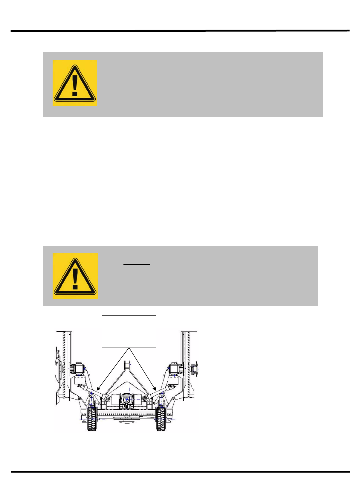
Transportation
First disengage the PTO drive and half raise the machine, fold the wings fully upright
and secure rams with locking bar (Fig. 6). Never transport along public highways with
the wings only supported by the hydraulics.
Please observe Public Highway Regulations, concerning the towing of implements,
and securely attach a registration and lighting board.
Warning
Do not run the machine with the wings raised, serious
damage will result to the drive line.
Warning
Avoid transporting machine at high speed over rough ground
Maximum speed on highway – 20mph (30kph).
Fig. 6
Transportation position
Secure wings
with transport
locking bar

Spearhead Multi-Cut 420
12
Machine Protection
To prevent gearbox damage all rotors are protected by slip clutches fitted to each of
the three rotor gearboxes. When cutting in extreme conditions where stumps, rocks
and other such solid objects are likely to be found it is recommended that the
operator reduces the engine revs to allow the blades to pivot more easily when
striking solid objects, and proceed with caution.
The clutch settings should not be altered without reference to Service and
Maintenance. Never over-tighten the pressure springs on the slip clutches (Fig. 7) as
this could result in severe damage to the gearbox and drive lines, as well as
invalidating the warranty.
If the machine has been laid up for any length of time, there is a risk of the
clutch plates rusting and seizing together. Never operate the machine in this
condition, as there will be no protection to the driveline and gearboxes against
shock loading. To free the clutch plates first slacken all pressure spring bolts and run
up the machine for a short period, deliberately try to cause the clutch to slip. Finally
re-tighten the tension spring bolts to their original length, taking great care not to
over-tighten. Alternatively refer to page 17.
If in any doubt, consult Spearhead’s Service Department or your local Spearhead
Dealer for further advice.
Fi
g
. 7 Sli
p
Clutch

Spearhead Multi-Cut 420
13
Service & Maintenance
Safety First
Never leave the tractor seat without first disengaging the PTO and
stopping the engine.
Ensure all rotating parts have stopped turning.
Never attempt any repairs, maintenance, service or any other
checks with the machine carried on the tractor hydraulics.
Always fully lower to the ground, or securely prop the machine on
substantial servicing stands.
Always replace all guards and retaining chains after
servicing/maintenance completed.
It is imperative that the following checks are carried out in order not to
invalidate your warranty; these are carried out before the first
operation, after the first hour, then after 4 hours.
These checks are:
1. Wheel nuts and tyre pressure (40psi).
2. Gearbox bolts, including the splitter box.
3. Retaining bolts on the drive shafts.
4. Grease all points including drive shaft tubes.
5. After the first 50 hours drain and replace the gearbox
lubrication. Replace with liquid grease (NLGI 000).
6. All other nuts and bolts
Warning
Never carry out any servicing or maintenance work without
first disengaging the PTO and then stopping the tractor
engine before leaving the seat.
On delivery of your machine check that the dealer has
completed the P.D.I form, ensure the warranty registration
form is completed and returned.

Spearhead Multi-Cut 420
14
Servicing & Maintenance
Daily
Grease all points.
Check bolts are tight on all gearboxes.
Check condition of blades and blade bushes; ensure all retaining bolts are
fully tight.
Check wheel nuts are tight.
Check tyre pressures – 40 P.S.I.
Check gearbox lubrication, replenish as necessary to the correct level line on
the dipstick, provided with each gearbox.
Fig. 8 Lubrication points
A Wing rams
B Wheel stem grease points
C Wheel bearings
D Wing hinges
E Input PTO shaft
F Wing PTO shafts
G Centre PTO coupling
H Headstock
Fig 8
RH blade rotation
Anti clockwise
LH blade rotation
Clockwise

Spearhead Multi-Cut 420
15
Service & Maintenance – Every 8 hours
Dismantle and clean the main P.T.O shafts sliding surfaces and re-grease;
failure to do this will result in serious damage to the gearboxes.
Grease all universal joints, if under-greased this joint will soon fail.
Grease the wing drive shaft tubes.
Lubricate the retaining collar on all the drive shaft guards (Fig. 9).
Grease PTO inner tube and push pins (Fig. 9).
Check all bolts are tightened to the correct Torque (Fig.10).
Torque Settings
The Torque figures given below are recommended maximum settings only.
Size: Tensile strength: Description: Torque setting:
Nm.
M16 8.8 Rotor gearbox bolts 280
¾ UNC 8.8 Splitter gearbox 280
M24 8.8 Blade bolts 950
Wheel nuts 270
M14 PTO clamp bolt 150
For maximum life and performance, the UJ must be greased regularly. Lubricate the driveline
up to 6 pumps of grease may be required.
The metal drive tubes must be greased to telescope properly.
Shielding is subject to damage from abuse and weathering. Replace all damaged
components and all shielding removed during maintenance.
Do not use PTO adapters drivelines. Replace special clamp bolts only with genuine OEM
parts, periodically check tightness of nuts.
Primary Input Shaft
Fig 10
Fig 9

Spearhead Multi-Cut 420
16
Servicing & Maintenance
Regularly
Check there is no wrapping of string, plastic, grass or other debris between
rotor boss and gearbox oil seal.
Inspect gearbox seals for leaks.
Clear grass and other debris from the deck.
Regularly check the rotor boss retaining castle nut for tightness. First remove
the split pin, select the correct size socket in 3/4” drive and fully tighten the
nut. When replacing the split pin, do not slacken the nut to align the hole,
always tighten. Failure to regularly check this nut will result in serious wear to
hub, which is expensive to repair.
It is most important that all gearbox bolts are regularly checked to be very
tight. When the machine is new there will be a ‘bedding in’ period where very
frequent checking is important.
Blades
Caution! When carrying out maintenance work on or near the blades be careful
of free-swinging blades over-centering and falling. It is recommended that
protective clothing including hardhat and goggles are worn.
The blades can be re-sharpened by grinding the cutting edges, care must be taken
that the blades are of the same weight and length after grinding. Do not overheat
when grinding, as this will affect the hardness of the blades. All the blades are free
swinging and swivel on hardened steel bushes, which are replaceable. When
replacing blades, it is important that blades are replaced in sets, in order to retain
balance of the rotor. Bushes must be replaced when new blades are to be fitted.
If the blades are showing any signs of severe wear, damage or cracking, they must
be replaced immediately. Never attempt to weld the blades, as this will make them
very brittle thus extremely dangerous. Do not take risks with the cutting blades - if in
doubt, replace.
L LH Blade
Spearhead Multi-Cut 420
17
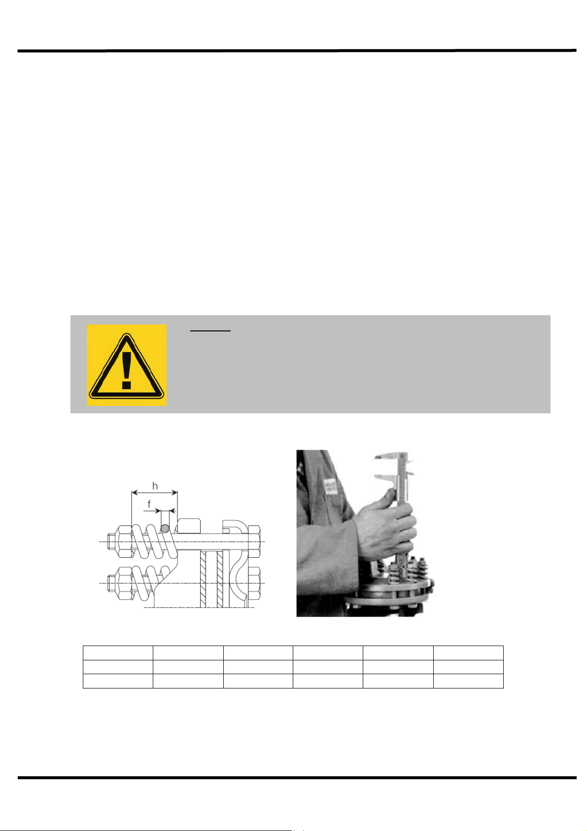
420 Slip Clutch Maintenance & Settings
Check the condition of the friction discs before use and following periods of storage.
Release the tension from the springs and turn the clutch body while holding the inner
P.T.O hub stationary, if unable to turn freely strip down clutch and free off seized
parts ensuring to remove all traces of rust. Rebuild and adjust the spring
compression to the original setting.
Following seasonal use, unload the spring tension and store clutch assembly in a dry
place. Check condition of friction linings and reset spring compression to original
height before use.
Should the assembly overheat due to frequent or prolonged clutch slipping, dismantle
for inspection. The original thickness of the lining is 3.0 mm, replace them when worn
to 2.0 mm. Clean up all contact surfaces and replace any damaged components
before assembly.
Fig 12 (h) Fig 12 (f) Position Setting Machine Part no
33.2 mm 7mm Centre 1000Nm 420 5770409
33.2 mm 7mm Wing 1000Nm 420 5770410
Warning
The slip clutch is there to protect the gearbox. If the
blades strike a large obstacle they may get damaged or
break - avoid these conditions.
Fig 12
Spearhead Multi-Cut 420
18
Servicing & Maintenance
Skids
When operating on abrasive soils, particularly in stubbles and similar conditions with
thin ground cover, excessive skid wear may be expected. To provide extra
protection and to prolong life of the skids, special hard facing rods are available.
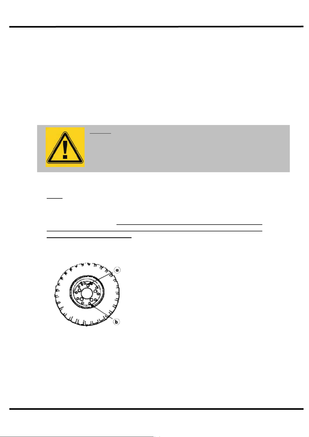
Wheels
When removing the wheels only remove the five larger hub nuts.
Never undo the smaller outer nuts (which are painted red for danger) when removing
the wheel.
The outer nuts must not be loosened until the valve has been removed and the inner
tube is entirely deflated. Then, and only then may the outer bolts can be
loosened. Failure to observe these precautions could seriously injure and
could even result in loss of life.
If in any doubt consult a tyre repair specialist or Spearhead’s Service Department.
Warning
Heavy-duty industrial tyres have been fitted to 420 Rotary Cutter for
convenience of tyre removal, the wheel rims are of the split rim type.
A Hub Nuts
B Outer Nuts (painted red)

Spearhead Multi-Cut 420
19
Storage
Before storing away, thoroughly wash the machine removing all traces of grass and
dirt. Great care must be taken when washing with high-pressure hoses, do not hold
the water jet close to the paintwork. Use steam cleaners with caution and be sure to
remove all detergents to avoid any discoloration or damage to the paintwork.
Grease all grease points until fresh grease shows. Liberally apply used engine oil
along the whole length of the hinges of each wing section. The centre clutch coupling
and wing shafts must be removed and stored under cover. Smear grease on the
hydraulic ram chromed rods for protection
After Storage
Disassemble clutches and with an emery cloth remove all traces of rust on the metal
clutch plates. Check condition of the friction plates, if there is any sign of over
heating, wear or cracking, replace with new. Do not attempt to use the machine with
damaged slip clutch plates.
Reassemble the clutch units and tighten the bolts to achieve the correct spring
length. Do not over tighten or the clutches will not work.
Check condition of tyres and pressure then follow the maintenance procedure
covered in the servicing part of this manual. Pay particular attention to the condition
of guards and blades.
Remember the 420 Rotary Cutter is designed to withstand the most rigorous
conditions and, with a little care and attention, will give many years of trouble free
service. So as not to invalidate the warranty and to avoid problems, use only genuine
parts and make sure the machine is not driven at a speed in excess of 1000r.p.m. on
the PTO.

Spearhead Multi-Cut 420
20
Trouble Shooting Guide
Broken or Damaged Blades
1. Raise cutting height to avoid
striking the ground
2. Remove or avoid obstacles
such as rocks
3. Check rotor speed
4. Ensure a steady feed into drive
(Do not snatch the PTO)
Damaged Blade Holder
1. As above
2. Failure to keep tight centre
retaining nut
Damage Gearboxes
1. Seized slip clutch.
2. Telescopic shafts bottoming out
3. Engaging drive with too much
power / revs
4. Lack of grease on sliding tubes
of drive shaft
Damage To PTO Shaft
1. Seized slip clutch
2. Telescopic tube bottoming out
3. Engaging drive with too much
power / revs
4. Turning too sharp
5. Not enough overlap
6. Lack of grease
7. Build up of Debris under drive
shaft
Gearbox Overheating
1. Incorrect oil/grease level
2. Incorrect grade of oil/grease
3. Incorrect operating speed
4. Machine overloaded
5. Rubbish around the gearbox
reducing air circulation
Slip Clutches Overheating
1. Machine overloaded
2. Incorrect operating speed
3. Incorrect setting
4. Blades hitting the ground
Oil Leak From Gearbox
1. Damaged shaft seal check for
foreign matter (wire-string)
2. Faulty breather
3. Damaged gasket
4. Incorrect oil/grease level
Metal Fatigue On Frame
1. Too fast a traveling / operating
speed for conditions
2. Wings not floating i.e. following
the ground contours (check tractor spool)
3. Used in a manner or condition
contra to its intended purpose
Excessive Skid Wear
1. Fit optional wheel kit to wings and set skids
above the ground.
Table of contents


