Ryobi RCT2800AD User manual

2-Cycle Petrol Trimmer
OPERATOR’S MANUAL
IMPORTANT MANUAL DO NOT THROW AWAY
RCT2800AD

2
INTRODUCTION
Read the Operator’s Manual(s) and follow all warnings and safety instructions. Failure to do so
can result in serious injury to the operator and/or bystanders.
WARNING!
RULES FOR SAFE OPERATION
DANGER:Failure to obey a safety warning
will result in serious injury to yourself or to
others. Always follow the safety
precautions to reduce the risk of fire,
electric shock and personal injury.
WARNING:Failure to obey a safety
warning can result in injury to yourself and
others. Always follow the safety
precautions to reduce the risk of fire,
electric shock and personal injury.
CAUTION: Failure to obey a safety warning
may result in property damage or personal
injury to yourself or to others. Always follow
the safety precautions to reduce the risk of
fire, electric shock and personal injury.
SAFETY ALERT SYMBOL: Indicates
danger, warning or caution. Attention is
required in order to avoid serious personal
injury. May be used in conjunction with
other symbols or pictographs.
SYMBOL MEANING
The purpose of safety symbols is to attract your
attention to possible dangers. The safety symbols,
and their explanations, deserve your careful attention
and understanding. The safety warnings do not by
themselves eliminate any danger. The instructions or
warnings they give are not substitutes for proper
accident prevention measures.
NOTE: Advises you of information or instructions vital
to the operation or maintenance of the
equipment.
SYMBOL MEANING
THANK YOU
Thank you for buying this quality product. This modern
outdoor power tool will provide many hours of useful
service. You will find it to be a great labor-saving device.
This operator’s manual provides you with easy-to-
understand operating instructions. Read the whole
manual and follow all the instructions to keep your new
outdoor power tool in top operating condition.
PRODUCT REFERENCES, ILLUSTRATIONS
AND SPECIFICATIONS
All information, illustrations and specifications in this
manual are based on the latest product information
available at the time of printing. We reserve the right to
make changes at any time without notice.
Copyright©2003 MTD SOUTHWEST INC
All Rights Reserved.
NOTE: PROOF OF PURCHASE WILL BE REQUIRED
FOR WARRANTY SERVICE.
Make sure you carefully read and understand this
manual before starting or operating this equipment.
TABLE OF CONTENTS
Introduction . . . . . . . . . . . . . . . . . . . . . . . . . . . . . . .2
Rules for Safe Operation . . . . . . . . . . . . . . . . . . . . .3
Know Your Unit . . . . . . . . . . . . . . . . . . . . . . . . . . . .5
Assembly Instructions . . . . . . . . . . . . . . . . . . . . . . .6
Oil and Petrol Information . . . . . . . . . . . . . . . . . . . .7
Starting/Stopping Instructions . . . . . . . . . . . . . . . . .8
Operating Instructions . . . . . . . . . . . . . . . . . . . . . . .9
Maintenance and Repair Instructions . . . . . . . . . . .10
Cleaning and Storage . . . . . . . . . . . . . . . . . . . . . . .14
Troubleshooting Chart . . . . . . . . . . . . . . . . . . . . . .15
Specifications . . . . . . . . . . . . . . . . . . . . . . . . . . . . .16

3
READ ALL INSTRUCTIONS
BEFORE OPERATING
•Read the instructions carefully. Be familiar with the
controls and proper use of the unit.
•Do not operate this unit when tired, ill or under the
influence of alcohol, drugs or medication.
•Children under the age of 15 must not use the unit;
teens may operate the unit with adult guidance.
•Inspect the unit before use. Replace damaged parts.
Check for petrol leaks. Make sure all fasteners are in
place and secure. Replace cutting attachment parts
that are cracked, chipped or damaged in any way.
Make sure the cutting attachment is properly installed
and securely fastened. Be sure that the cutting
attachment shield is properly attached, and positioned
as recommended. Failure to do so can result in
personal injury to the operator and bystanders, as well
as damage to the unit.
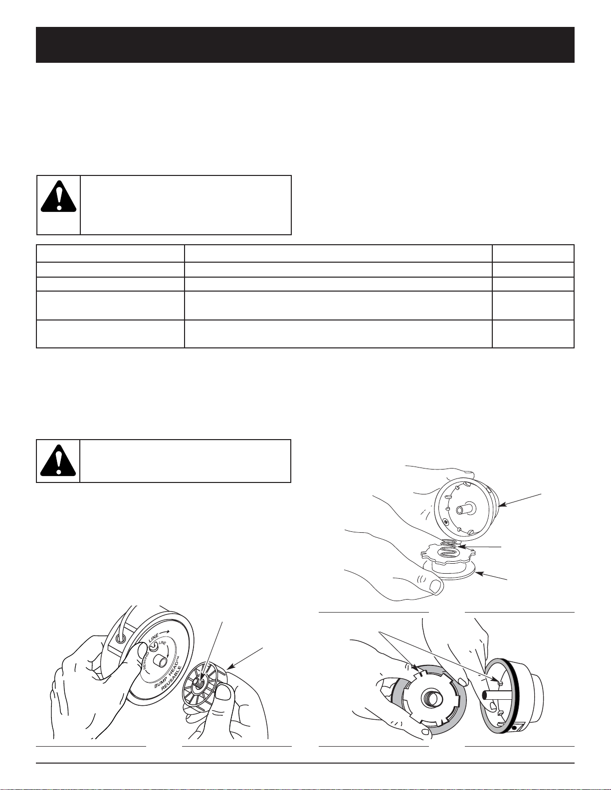
•Use only 0.080 inch (2.03 mm) diameter original
equipment manufacturer replacement line. Never use
metal-reinforced line, wire, chain or rope. These can
break off and become dangerous projectiles.
•Be aware of risk of injury to the head, hands and feet.
•Clear the area to be cut before each use. Remove
rocks, broken glass, nails, wire, string and other
objects which may be thrown or become entangled in
the cutting attachment. Clear the area of children,
bystanders and pets; keep them outside a 50-foot
(15 m.) radius, at a minimum. Even then, they are still
at risk from thrown objects. Encourage bystanders to
wear eye protection. If you are approached, stop the
unit immediately.
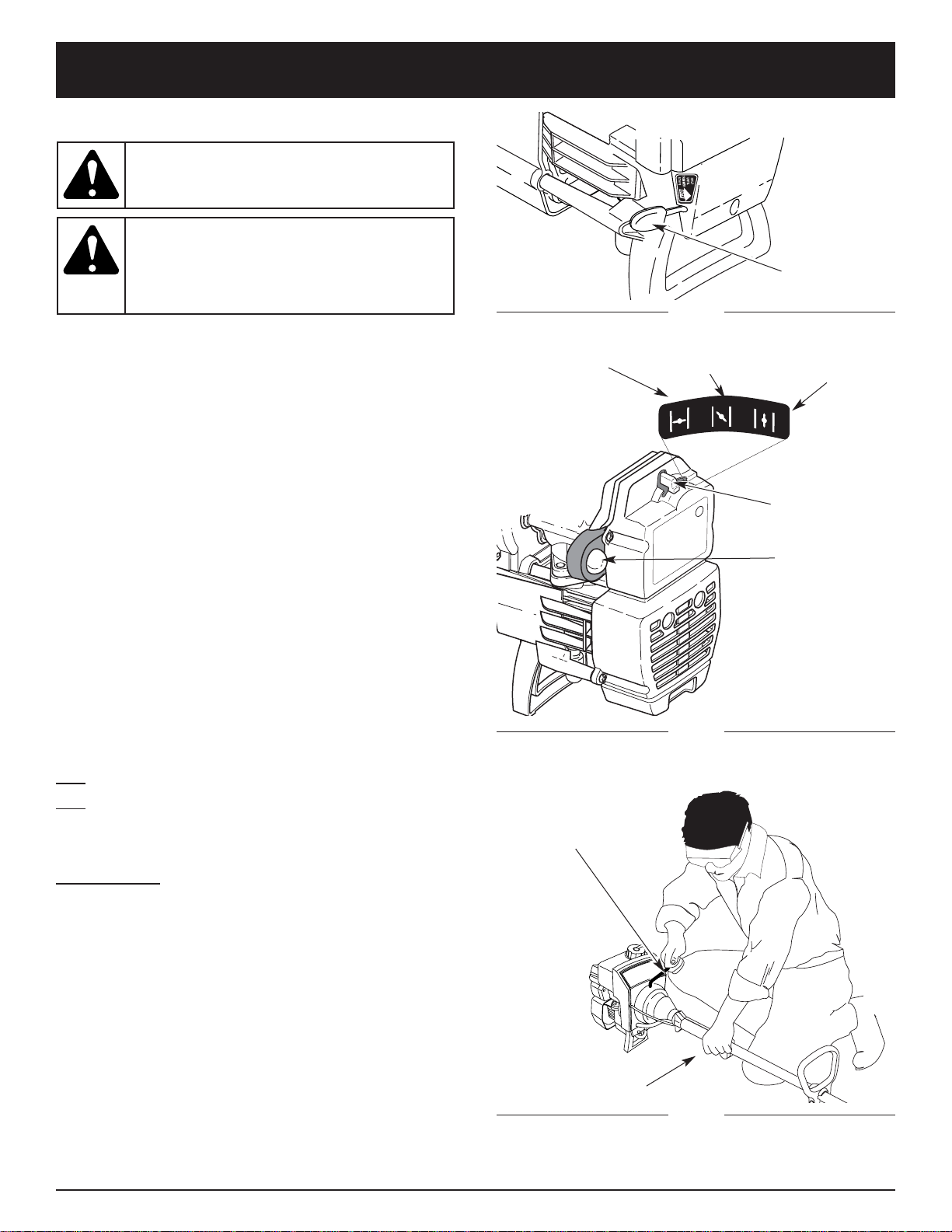
•Squeeze the throttle control and check that it returns
automatically to the idle position. Make all adjustments
or repairs before using the unit.
•This unit was not designed to be used as a brushcutter.
Do not attach or operate this unit with any type of
brushcutting blade or brushcutting attachment.
SAFETY WARNINGS FOR PETROL TRIMMERS
•Store petrol only in containers specifically designed
and approved for the storage of such materials.
•Avoid creating a source of ignition for spilled petrol.
Do not start the engine until petrol vapors dissipate.
• IMPORTANT SAFETY INFORMATION •
•Always stop the engine and allow it to cool before
filling the petrol tank. Never remove the petrol tank
cap or add petrol when the engine is hot. Never
operate the unit without the petrol cap securely in
place. Loosen the petrol tank cap slowly to relieve any
pressure in the tank.
•Add petrol in a clean, well-ventilated outdoor area
where there are no sparks or flames. Remove the
petrol cap slowly, and only after the engine stops. Do
not smoke while fueling or mixing petrol. Wipe up any
spilled petrol from the unit immediately.
•Move the unit at least 30 feet (9.1 m) from the fueling
source and site before starting the engine. Do not
smoke. Keep sparks and open flames away from the
area while adding petrol or operating the unit.
WHILE OPERATING
•Never start or run the unit inside a closed room or
building. Breathing exhaust fumes can be fatal.
Operate this unit only in a well-ventilated outdoor area.
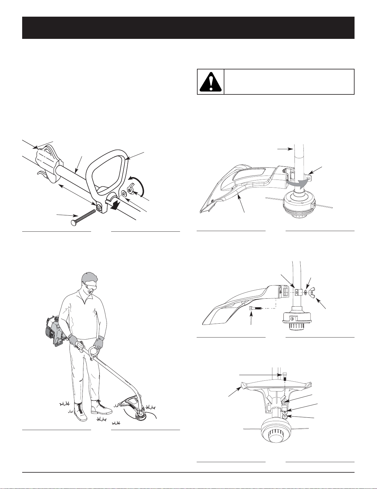
•Wear safety glasses or goggles that meet ANSI Z87.1
standards and are marked as such. Wear ear/hearing
protection when operating this unit. Wear a face or
dust mask if the operation is dusty.
•Wear heavy long pants, boots, gloves and a long
sleeve shirt. Do not wear loose clothing, jewelry, short
pants, sandals or go barefoot. Secure hair above
shoulder level.
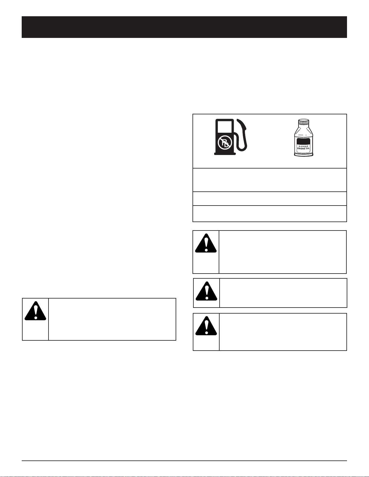
•The cutting attachment shield must always be in place
while operating the unit. Do not operate unit without
both trimming lines extended, and the proper line
installed. Do not extend the trimming line beyond the
length of the shield.
•This unit does not have a clutch. The cutting
attachment continues rotating when the engine is
idling. If it does not, have the unit adjusted by an
authorized service technician.
•Adjust the D-handle to your size in order to provide the
best grip.
•Be sure the cutting attachment is not in contact with
anything before starting the unit.
•Use the unit only in daylight or good artificial light.
•Avoid accidental starting. Be in the starting position
whenever pulling the starter rope. The operator and
unit must be in a stable position while starting. Refer
to Starting/Stopping Instructions.
•Use the right tool. Only use this tool for its intended
purpose.
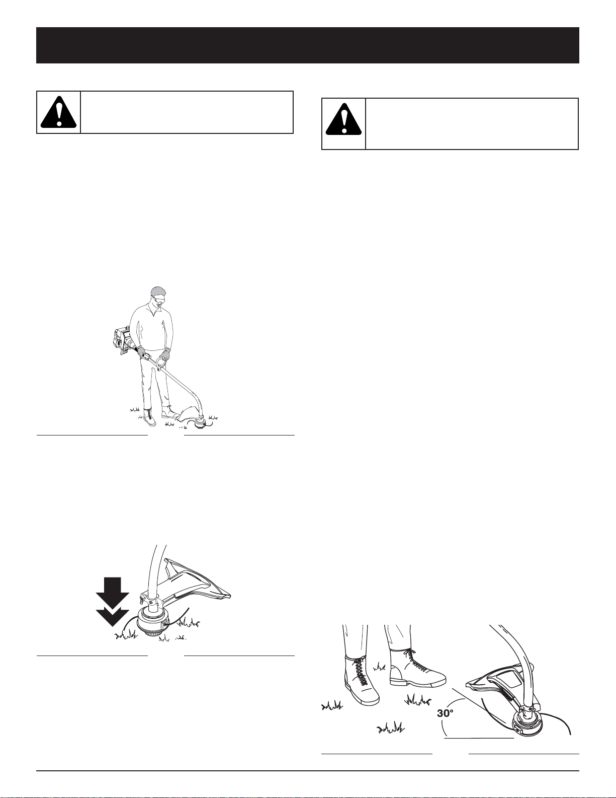
•Do not overreach. Always keep proper footing and
balance.
•Always hold the unit with both hands when operating.
Keep a firm grip on both handles or grips.
•Keep hands, face, and feet at a distance from all
moving parts. Do not touch or try to stop the cutting
attachment when it rotates.
WARNING:When using the unit, you must
follow the safety rules. For your own safety
and that of bystanders, please read these
instructions before operating the unit.
Please keep the instructions for later use.
WARNING:Petrol is highly flammable, and
its vapors can explode if ignited. Take the
following precautions:
RULES FOR SAFE OPERATION

4
SYMBOL MEANING
•SAFETY ALERT SYMBOL
Indicates danger, warning, or
caution. May be used in conjunction
with other symbols or pictographs.
•WARNING - READ OPERATOR'S
MANUAL
Read the Operator’s Manual(s) and
follow all warnings and safety
instructions. Failure to do so can
result in serious injury to the
operator and/or bystanders.
•UNLEADED PETROL
Always use clean, fresh unleaded
petrol.
•WEAR EYE AND HEARING
PROTECTION
WARNING:Thrown objects and loud
noise can cause severe eye injury and
hearing loss. Wear eye protection
meeting ANSI Z87.1 standards and ear
protection when operating this unit.
Use a full face shield when needed.
SAFETY AND INTERNATIONAL SYMBOLS
This operator's manual describes safety and international symbols and pictographs that may appear on this product.
Read the operator's manual for complete safety, assembly, operating and maintenance and repair information.
SYMBOL MEANING
•HOT SURFACE WARNING
Do not touch a hot muffler or
cylinder. You may get burned. These
parts get extremely hot from
operation. When turned off they
remain hot for a short time.
•CHOKE CONTROL
A • FULL choke position
B • PARTIAL choke position
C • RUN position
•OIL
Refer to operator's manual for the
proper type of oil.
• THROWN OBJECTS AND
ROTATING CUTTER CAN
CAUSE SEVERE INJURY
WARNING:Do not operate without
the cutting attachment shield in place.
Keep away from the rotating cutting
attachment.
123
•Do not touch the engine, gear housing or muffler.
These parts get extremely hot from operation, even
after the unit is turned off.
•Do not operate the engine faster than the speed
needed to cut, trim or edge. Do not run the engine at
high speed when not cutting.
•Always stop the engine when cutting is delayed or
when walking from one cutting location to another.
•If you strike or become entangled with a foreign
object, stop the engine immediately and check for
damage. Do not operate before repairing damage. Do
not operate the unit with loose or damaged parts.
•Stop the unit, switch the engine to off, and disconnect
the spark plug for maintenance or repair.
•Use only original equipment manufacturer replacement
parts and accessories for this unit. These are available
from your authorized service dealer. Use of any
unauthorized parts or accessories could lead to
serious injury to the user, or damage to the unit, and
void your warranty.
•Keep unit clean of vegetation and other materials.
They may become lodged between the cutting
attachment and shield.
•To reduce fire hazard, replace a faulty muffler and
spark arrestor. Keep the engine and muffler free from
grass, leaves, excessive grease or carbon build up.
OTHER SAFETY WARNINGS
•Never store a fueled unit inside a building where fumes
may reach an open flame or spark.
•Allow the engine to cool before storing or transporting.
Be sure to secure the unit while transporting.
•Store the unit in a dry area, locked up or up high to
prevent unauthorized use or damage, out of the reach
of children.
•Never douse or squirt the unit with water or any other
liquid. Keep handles dry, clean and free from debris.
Clean after each use, see Cleaning and Storage
instructions.
•Keep these instructions. Refer to them often and use
them to instruct other users. If you loan someone this
unit, also loan them these instructions.
SAVE THESE INSTRUCTIONS
RULES FOR SAFE OPERATION

5
RULES FOR SAFE OPERATION
APPLICATIONS
As a trimmer:
•Cutting grass and light weeds
•Edging
•Decorative trimming around trees, fences, etc.
KNOW YOUR UNIT
Petrol Cap
Throttle
Control
D-Handle
Shaft
Grip Primer
Bulb
Choke
Lever
Air Filter/Muffler
Cover
Spark Plug
Shaft
Tube
Starter
Rope Grip
Line Cutting Blade
Muffler
Stop Switch
Cutting
Attachment
Cutting
Attachment Shield

6
ASSEMBLY INSTRUCTIONS
Fig. 2
INSTALL THE CUTTING ATTACHMENT SHIELD
Use the following instructions if the cutting attachment
shield on your unit is not installed.
1. Place the cutting attachment shield onto the shaft
housing. Be sure the guard mounting bracket slides
into the slot on the edge of the cutting shield. Rotate
the shield into place, counterclockwise. The holes in
the guard mounting bracket and cutting attachment
shield will line up (Fig. 3).
INSTALL AND ADJUST THE D-HANDLE
1. Push the D-handle down onto the shaft housing so
that the handle slants towards the shaft grip (Fig. 1).
The squared bolt hole in the handle is to the right.
2. Insert the shoulder bolt into the squared hole in the
handle and push through. On the left side of the
handle, place the washer on the bolt, then screw the
wing nut onto the bolt. Do not tighten until you make
the handle adjustment.
3. Rotate the D-handle to place the grip above the top
of the shaft housing. Place it a minimum of 6 inches
(15.24 cm) from the end of the shaft grip.
4. While holding the unit in the operating position
(Fig. 2), position the D-handle to the location that
provides you the best grip.
5. Tighten the wing nut until the D-handle is secure.
Fig. 1
Bolt Washer
Wing Nut
Tighten
Shaft Grip
D-Handle
Minimum 6 inches
(15.24 cm)
Shaft Housing
WARNING: To prevent serious personal
injury, never operate the trimmer without
the cutting attachment shield in place.
2. From inside the cutting attachment shield, push the square
bolt through the hole until the threaded end protrudes
through the guard mounting bracket (Fig. 4).
Guard
Mounting
Bracket
Shaft Housing
Square Bolt
Cutting Attachment
Shield
3. Put the washer on the bolt, then screw the wing nut
onto the bolt and tighten. Figure 5 shows the
installation process from underneath the unit.
Guard
Mounting
Bracket
Wing Nut
Cutting Attachment and Shield: Underside View
Cutting
Attachment
Shield Wing Nut
Washer
Square Bolt
Washer
Hole
Fig. 3
Fig. 4
Fig. 5

7
OIL AND PETROL INFORMATION
NOTE: Dispose of the old petrol/oil mix in accordance to
Federal, State and Local regulations.
CAUTION: For proper engine operation and
maximum reliability, pay strict attention to
the oil and petrol mixing instructions on the
2-cycle oil container. Using improperly
mixed petrol can severely damage the
engine.
WARNING: Petrol is extremely flammable.
Ignited Vapors may explode. Always stop
the engine and allow it to cool before filling
the petrol tank. Do not smoke while filling
the tank. Keep sparks and open flames at a
distance from the area.
WARNING: Remove petrol cap slowly to
avoid injury from petrol spray. Never operate
the unit without the petrol cap securely in
place
.
WARNING: Add petrol in a clean, well
ventilated area outdoors. Wipe up any
spilled petrol immediately. Avoid creating a
source of ignition for spilt petrol. Do not start
the engine until petrol vapors dissipate.
OIL AND PETROL MIXING INSTRUCTIONS
Old and/or improperly mixed petrol are the main reasons
for the unit not running properly. Be sure to use fresh,
clean unleaded petrol. Follow the instructions carefully
for the proper petrol/oil mixture.
Definition of Blended Fuels
Today's fuels are often a blend of petrol and oxygenates
such as ethanol, methanol, or MTBE (ether). Alcohol-
blended petrol absorbs water. As little as 1% water in
the petrol can make petrol and oil separate. It forms
acids when stored. When using alcohol-blended petrol,
use fresh petrol (less than 60 days old).
Using Blended Fuels
If you choose to use a blended petrol, or its use is
unavoidable, follow recommended precautions:
•Always use the fresh petrol mix explained in your
operator's manual
•Always agitate the petrol mix before fueling the unit
•Drain the tank and run the engine dry before storing
the unit
Using Petrol Additives
The bottle of 2-cycle oil that came with your unit
contains a petrol additive which will help inhibit
corrosion and minimize the formation of gum deposits. It
is recommended that you use our 2-cycle oil with this
unit.
If unavailable, use a good 2-cycle oil designed for
air-cooled engines along with a petrol additive, such as
STA-BIL®Petrol Stabilizer or an equivalent. Add 0.8 oz.
(23 ml.) of petrol additive per gallon of petrol according
to the instructions on the container. NEVER add petrol
additives directly to the unit's petrol tank.
Thoroughly mix the proper ratio of 2-cycle engine oil
with unleaded petrol in a separate petrol can. Use a 40:1
petrol/oil ratio. Do not mix them directly in the engine
petrol tank. See the table below for specific petrol and
oil mixing ratios.
NOTE: One gallon (3.8 liters) of unleaded petrol mixed
with one 3.2 oz. (95 ml.) bottle of
2-cycle oil makes a 40:1 petrol/oil ratio.
+
UNLEADED PETROL 2 CYCLE OIL
1 US. GALLON + 3.2 FL. OZ.
(3.8 LITERS) (95 ml)
1 LITER + 25 ml
MIXING RATIO - 40:1

8
STARTING INSTRUCTIONS
1. Mix petrol with oil. Fill petrol tank with petrol/oil
mixture. Refer to Oil and Petrol Mixing Instructions.
2. Fully press and release the primer bulb 10 times,
slowly. Some amount of petrol should be visible in
the primer bulb and petrol lines (Fig. 7). If you can’t
see petrol in the bulb, press and release the bulb as
many times as it takes before you can see petrol in it.
3. Place the choke lever in Position 1(Fig. 7).
4. Crouch in the starting position (Fig. 8) and squeeze
the throttle control.
5. Pull the starter rope out a short distance, until you feel
some resistance. This is usually around 2-4 inches.
Then pull the rope smoothly and briskly. Repeat this 5
times.
6. Place the choke lever in Position 2.
7. While squeezing the throttle control, pull the starter
rope in the same manner as explained in Step 5. Pull
1 to 3 times to start the engine.
8. Keep the throttle squeezed and allow the engine to
warm up for 15 to 30 seconds.
9. Place the choke lever in Position 3. The unit is ready
for use.
IF... The engine does not start, go back to step 2.
IF... The engine fails to start after a few attempts, place
the choke lever in Position 3and squeeze the
throttle control. Pull the starter rope briskly 3 to 8
times. The engine should start. If not, repeat.
IF WARM... If the engine is already warm, start the
unit with the choke lever in Position 2. After the unit
starts, move the choke lever to Position 3.
WARNING:
Operate this unit only in a well-
ventilated outdoor area. Carbon monoxide
exhaust fumes can be lethal in a confined area.
WARNING: Avoid accidental starting. Make
sure you are in the starting position when
pulling the starter rope (Fig. 8).
To avoid
serious injury, the operator and unit must be
in a stable position while starting.
STARTING/STOPPING INSTRUCTIONS
Stop Switch
Fig. 8
Choke Lever
Position 1 Position 3
Position 2
Starter Rope
Throttle Control
Primer Bulb
STOPPING INSTRUCTIONS
1. Release your hand from the throttle control. Allow
the engine to cool down by idling.
2. Press and hold the Stop Switch until the engine
stops (Fig 6).
Fig. 6
Fig. 7

9
OPERATING INSTRUCTIONS
NOTE: Do not rest the Bump Head™ on the ground
while the unit is running.
Some line breakage will occur from:
•Entanglement with foreign matter
•Normal line fatigue
•Attempting to cut thick, stalky weeds
•Forcing the line into objects such as walls or fence posts
TIPS FOR BEST TRIMMING RESULTS
•Keep the cutting attachment parallel to the ground.
•Do not force the cutting attachment. Allow the tip of the
line to do the cutting, especially along walls. Cutting with
more than the tip will reduce cutting efficiency and may
overload the engine.
•Cut grass over 8 inches (200 mm) by working from top
to bottom in small increments to avoid premature line
wear or engine drag.
•Cut from right to left whenever possible. Cutting to the
right improves the unit's cutting efficiency. Clippings are
thrown away from the operator.
•Slowly move the trimmer into and out of the cutting
area at the desired height. Move either in a forward-
backward or side-to-side motion. Cutting shorter
lengths produces the best results.
•Trim only when grass and weeds are dry.
•The life of your cutting line is dependent upon;
• Adherence of the listed trimming techniques
• What vegetation is cut
• Where vegetation is cut
For example, the line will wear faster when trimming against
a foundation wall as opposed to trimming around a tree.
HOLDING THE TRIMMER
Before operating the unit, stand in the operating position
(Fig. 9). Check for the following:
•The operator is wearing eye protection and proper
clothing
•With a slightly-bent right arm, the operator’s right hand
is holding the shaft grip
•The operator’s left arm is straight, the left hand holding
the D-handle
•The unit is at waist level
•
The cutting attachment is parallel to the ground and
easily contacts the grass without the need to bend ove
r
ADJUSTING TRIMMING LINE LENGTH
The Bump Head™ cutting attachment allows you to
release trimming line without stopping the engine. To
release more line, lightly tap the cutting attachment on the
ground (Fig. 10) while operating the trimmer at high speed.
NOTE:Always keep the trimming line fully extended.
Line release becomes more difficult as cutting
line becomes shorter
Fig. 10
CAUTION:
Do not remove or alter the line
cutting blade assembly. Excessive line length
may lead to serious personal injury or damage
to the unit.
WARNING: Always wear eye, hearing, foot
and body protection to reduce the risk of
injury when operating this unit.
Each time the head is bumped, about 1 inch (25.4 mm)
of trimming line releases. A blade in the cutting
attachment shield will cut the line to the proper length if
any excess line is released.
For best results, tap the bump knob on bare ground or
hard soil. If you attempt a line release in tall grass, the
engine may stall. Always keep the trimming line fully
extended. Line release becomes more difficult when the
cutting line gets shorter.
DECORATIVE TRIMMING
Decorative trimming is accomplished by removing all
vegetation around trees, posts, fences, etc.
Rotate the whole unit so that the cutting attachment is at
a 30° angle to the ground (Fig. 11).
Fig. 11
Fig. 9

10
MAINTENANCE SCHEDULE
Perform these required maintenance procedures at the
frequency stated in the table. These procedures should
also be a part of any seasonal tune-up.
NOTE: Some maintenance procedures may require
special tools or skills. If you are unsure about
these procedures take your unit to any non-road
engine repair establishment, individual or
authorized service dealer.
NOTE: Maintenance, replacement, or repair of the
emission control devices and system may be
performed by any non-road engine repair
establishment, individual or authorized service
dealer.
In order to assure peak performance of your engine,
inspection of the engine exhaust port may be necessary
after 50 hours of operation. If you notice lost RPM, poor
performance or general lack of acceleration, this service
may be required. If you feel your engine is in need of this
inspection, refer service to any non-road engine repair
establishment, individual or authorized service dealer for
repair. DO NOT attempt to perform this process yourself
as engine damage may result from contaminants
involved in the cleaning process for the port.
FREQUENCY MAINTENANCE REQUIRED REFER TO
Before starting engine Fill petrol tank with fresh petrol Page 7
Every 10 hours Clean and re-oil air filter Page 12
Every 25 hours Check and clean spark arrestor
Check spark plug condition and gap Page 13
Page 14
Every 50 hours Inspect exhaust port and spark arrestor screen for clogging or
obstruction to assure maximum performance levels Page 13
MAINTENANCE AND REPAIR INSTRUCTIONS
WARNING: To prevent serious injury, never
perform maintenance or repairs with unit
running. Always service and repair a cool unit.
Disconnect the spark plug wire to ensure that
the unit cannot start.
LINE INSTALLATION
This section covers both SplitLine™ and standard single
line installation.
Always use original equipment manufacturer 0.080 in.
(2.03 mm) replacement line. Line other than the specified
may make the engine overheat or fail.
There are two methods to replace the trimming line:
• Wind the inner reel with new line
• Install a prewound inner reel
Winding the Existing Inner Reel
1. Hold the outer spool with one hand and unscrew the
Bump Knob™ counterclockwise (Fig. 12). Inspect the
bolt inside the Bump Knob to make sure it moves
freely. Replace the Bump Knob if damaged.
2. Remove the inner reel from the outer spool (Fig. 13).
3. Remove spring from the inner reel (Fig. 13).
4. Use a clean cloth to clean the the inner reel, spring,
shaft, and inner surface of the outer spool.
5. Check the indexing teeth on the inner reel and outer
spool for wear (Fig. 14). If necessary, remove burrs or
replace the reel and spool.
WARNING: Never use metal-reinforced
line, wire, chain or rope. These can break
off and become dangerous projectiles.
Bump Knob™
Bolt
Fig. 12
Inner Reel
Spring
Outer Spool
Indexing Teeth
Fig. 14
Fig. 13

11
MAINTENANCE AND REPAIR INSTRUCTIONS
Fig. 19
Fig. 15
NOTE: SplitLine™ can only be used with the inner reel
with the slotted holes. Single line can be used on
either type of inner reel. Use Figure 15 to identify
the inner reel you have.
NOTE: Always use the correct line length when installing
trimming line on the unit. The line may not release
properly if the line is too long.
Single Line Installation
Go To Step 8 for SplitLine™ Installation
6. Take approximately 20 feet (7 m) of new trimming
line, loop it into two equal lengths. Insert each end of
the line through one of the two holes in the inner reel
(Fig. 16). Pull the line through the inner reel so that
the loop is as small as possible.
7. Wind the lines in tight even layers, onto the reel
(Fig. 17). Wind the line in the direction indicated on
the inner reel. Place your index finger between the
two lines to stop the lines from overlapping. Do not
overlap the ends of the line. Proceed to step 11.
SplitLine™ Installation
8. Take approximately 10 feet (3 m) of new trimming
line. Insert one end of the line through one of the two
holes in the inner reel (Fig. 18). Pull the line through
the inner reel until only about 4 inches is left out.
9. Insert the end of the line into the open hole in the
inner reel and pull the line tight to make the loop as
small as possible (Fig. 18).
10. Before winding, split the line back about 6 inches.
11. Wind the line in tight even layers in the direction
indicated on the inner reel.
NOTE: Failure to wind the line in the direction indicated will
cause the cutting attachment to operate incorrectly.
Slotted
Holes
For Use with SplitLine™
or Single Line
For Use with Single
Line ONLY
Holding Slots
NOTE: The spring must be assembled on the inner reel
before reassembling the cutting attachment.
14. Hold the inner reel in place and install the bump knob
by turning clockwise. Tighten securely.
12. Insert the ends of the line into the two holding slots
(Fig. 19).
13. Insert the ends of the line through the eyelets in the
outer spool and place inner reel with spring inside the
outer spool (Fig. 20). Push the inner reel and outer
spool together. While holding the inner reel and outer
spool, grasp the ends and pull firmly to release the
line from the holding slots in the reel.
Loop
Fig. 16
Fig. 17
Loop
Fig. 18
Spring
Fig. 20

12
MAINTENANCE AND REPAIR INSTRUCTIONS
AIR FILTER MAINTENANCE
Removing the Air Filter/Muffler Cover
1.
Place the choke lever in Position 2.
NOTE: The choke lever must be in
Position 2
to remove
the air filter/ muffler cover.
2. Remove the four (4) screws securing the air
filter/muffler cover (Fig. 21). Use a flat blade or
T-20 Torx bit screwdriver.
3. Pull the cover from the engine. Do not force.
INSTALLING A PREWOUND REEL
1. Hold the outer spool with one hand and unscrew the
bump knob counterclockwise (Fig. 12). Inspect the bolt
inside the bump knob to make sure it moves freely.
Replace the bump knob if damaged.
2. Remove the old inner reel from the outer spool
(Fig. 13).
3. Remove the spring from the old inner reel
(Fig. 13).
4. Place the spring in the new inner reel.
NOTE:The spring must be assembled on the inner reel
before reassembling the cutting attachment.
5. Insert the ends of the line through the eyelets in the
outer spool (Fig. 20).
6. Place the new inner reel inside the outer spool. Push the
inner reel and outer spool together. While holding the
inner reel and outer spool, grasp the ends and pull firmly
to release the line from the holding slots in the spool.
7. Hold the inner reel in place and install the bump knob
by turning clockwise. Tighten securely.
Replacement Parts
See Accessories / Replacement Parts.
WARNING: To avoid serious personal injury,
always turn your trimmer off and allow it to
cool before you clean or service it.
Cleaning the Air Filter
Clean and re-oil the air filter every 10 hours of operation.
It is an important item to maintain. Failure to maintain the
air filter will VOID the warranty.
1. Remove air filter/muffler cover. Refer to Removing
the Air Filter/Muffler Cover.
2. Turn cover over and look inside to locate the air filter.
Remove the air filter from inside the air filter/muffler
cover (Fig. 22).
3. Wash the filter in detergent and water (Fig. 23). Rinse
the filter thoroughly. Squeeze out excess water. Allow
it to dry completely.
4. Apply enough clean SAE 30 oil to lightly coat the filter
(Fig. 24).
5. Squeeze the filter to spread and remove excess oil
(Fig. 25).
Fig. 22 Fig. 23
Fig. 24 Fig. 25
6. Replace the air filter inside the air filter/muffler cover
(Fig. 22).
NOTE: Operating the unit without the air filter and air
filter/muffler cover assembly will VOID the
warranty.
Reinstalling the Air Filter/Muffler Cover
1. Place the air filter/muffler cover over the back of the
carburetor and muffler. Align the screw holes.
2. Insert the four (4) screws into the holes in the air
filter/muffler cover (Fig. 21) and tighten.
Do not over tighten.
Air Filter
Inside Muffler
Cover
Choke Lever
Screws Screws
Position 2
Fig. 21

13
SPARK ARRESTOR MAINTENANCE
1. Remove air filter/muffler cover. Refer to Removing
the Air Filter/Muffler Cover.
2. Locate muffler front and the two (2) bolts securing it
to the engine (Fig. 26). Remove the two (2) bolts
using a flatblade screwdriver or 5/16-inch socket or
nut driver. Pull muffler off of the engine.
3. Turn muffler over to the back side and locate the
exhaust gasket. Remove the muffler gasket from the
muffler (Fig. 26).
NOTE: If the exhaust gasket is torn or damaged, replace
it with a new gasket before reassembling muffler.
4. Using a small flatblade screwdriver, carefully pry up
the spark arrestor from the recessed hole (Fig. 27).
Remove the spark arrestor from the muffler.
5. Clean the spark arrestor with a wire brush. Replace it
if it is damaged or if it is impossible to clean
thoroughly (Fig. 27).
6. Reinstall the spark arrestor by pressing it into the
recessed hole on the muffler's back side. Make sure
it fits tightly against the muffler and is not raised up.
7. Place the exhaust gasket against muffler's back side.
Align the gasket bolt holes with the bolt holes in the
muffler. While holding exhaust gasket in place, insert
the bolts into the muffler's front side (Fig. 26).
8. Place the muffler (with the exhaust gasket in place
and bolts inserted), against the engine, aligning the
bolt holes. Tighten the bolts to secure the muffler to
the engine.
If using a torque wrench, torque to:
80-90 in.•lb. (9-10.2 N•m)
9. Reinstall the air filter/muffler cover.
Fig. 27
Fig. 26
Muffler - Front Side Muffler - Back Side
Bolts Exhaust
Gasket
Spark
Arrestor
Muffler - Back Side
Spark Arrestor Flatblade
Screwdriver
Spark Arrestor
WARNING:
If the muffler is not tightened
securely, it could fall off causing damage to
the unit and possible serious personal injury
MAINTENANCE AND REPAIR INSTRUCTIONS
Check Petrol Mixture
Old and/or improperly mixed petrol is usually the reason
for improper unit performance. Drain and refill the tank
with fresh, properly-mixed petrol prior to making any
adjustments. Refer to Oil and Petrol Information.
Clean Air Filter
The condition of the air filter is important to the operation
of the unit. A dirty air filter will restrict air flow and
change the air/petrol mixture. This is often mistaken for
an out of adjustment carburetor. Check the condition of
the air filter before adjusting the idle speed screw. Refer
to Air Filter Maintenance.
Adjust Idle Speed Screw
If, after checking the petrol mixture and cleaning the air
filter, the engine still will not idle, adjust the idle speed
screw as follows:
1. Start the engine and let it run at a high idle for a
minute to warm up. Refer to Starting/Stopping
Instructions.
CARBURETOR ADJUSTMENT
The idle speed of the engine is adjustable through the air
filter/muffler cover (Fig. 28).
NOTE: Careless adjustments can seriously damage your
unit. An authorized service dealer should make
carburetor adjustments.
WARNING: The cutting attachment will spin
during idle speed adjustments. Wear
protective clothing and observe all safety
instructions to prevent serious personal injury.
Idle Speed Screw
Fig. 28

14
CLEANING
Use a small brush to clean off the outside of the unit.
Do not use strong detergents. Household cleaners that
contain aromatic oils such as pine and lemon, and
solvents such as kerosene, can damage plastic housing
or handle. Wipe off any moisture with a soft cloth.
STORAGE
•Never store a fueled unit where fumes may reach an
open flame or spark.
•Allow the engine to cool before storing.
•Store the unit locked up to prevent unauthorized use
or damage.
•Store the unit in a dry, well-ventilated area.
•Store the unit out of the reach of children.
LONG TERM STORAGE
If you plan on storing the unit for an extended time, use
the following storage procedure:
1. Drain all petrol from the petrol tank into a container
with the same 2-cycle petrol mixture. Do not use
petrol that has been stored for more than 60 days.
Dispose of the old petrol/oil mix in accordance to
Federal, State and Local regulations.
2. Start the engine and allow it to run until it stalls. This
ensures that all petrol has been drained from the
carburetor.
3. Allow the engine to cool. Remove the spark plug and
put 1 oz. (30 ml) of any high quality motor oil or
2-cycle oil into the cylinder. Pull the starter rope
slowly to distribute the oil. Reinstall the spark plug.
NOTE: Remove the spark plug and drain all of the oil
from the cylinder before attempting to start the
trimmer after storage.
4. Thoroughly clean the unit and inspect it for any loose
or damaged parts. Repair or replace damaged parts
and tighten loose screws, nuts or bolts. The unit is
ready for storage.
TRANSPORTING
•Allow the engine to cool before transporting.
•Drain petrol from unit.
•Tighten petrol cap before transporting.
•Secure the unit while transporting.
WARNING: To avoid serious personal injury,
always turn your trimmer off and allow it to
cool before you clean or service it.
2. Release the throttle trigger and let the engine idle. If the
engine stops, insert a small phillips or flat blade
screwdriver into the hole in the air filter/muffler cover (Fig.
28). Turn the idle speed screw in, clockwise, 1/8 of a
turn at a time (as needed) until the engine idles smoothly.
3. If the engine appears to be idling too fast, turn the
idle speed screw counterclockwise 1/8 of a turn at
a time (as needed), to reduce idle speed.
Checking the petrol mixture, cleaning the air filter, and
adjusting the idle speed should solve most engine
problems. If not and all of the following are true:
•the engine will not idle
•the engine hesitates or stalls on acceleration
•there is a loss of engine power
Have the carburetor adjusted by an authorized service dealer.
REPLACING THE SPARK PLUG
Use a Champion RDJ7Y spark plug, or equivalent. The
correct air gap is 0.020 inch (0.5 mm). Remove the plug
after every 25 hours of operation and check its condition.
1. Stop the engine and allow it to cool. Grasp the plug
wire firmly and pull it from the spark plug.
2. Clean around the spark plug. Remove the spark plug
from the cylinder head by turning a 5/8-inch socket
counterclockwise.
3. Replace a cracked, fouled or dirty spark plug. Set the air
gap at 0.020 in. (0.5 mm) using a feeler gauge (Fig. 29).
4. Install a correctly-gapped spark plug in the cylinder
head. Tighten by turning the 5/8-inch socket
clockwise until snug.
If using a torque wrench torque to 110-120 in.•lb. (12.3-
13.5 N•m). Do not over tighten.
0.020 in.
(0.5 mm)
Fig. 29
CAUTION: Do not sand blast, scrape or
clean electrodes. Grit in the engine could
damage the cylinder.
WARNING: To prevent serious personal
injury, make sure the cutting attachment
has stopped rotating when it is turned off
and you set it down.
MAINTENANCE AND REPAIR INSTRUCTIONS

15
If further assistance is required, contact your authorized service dealer.
CAUSE ACTION
Cutting attachment bound with grass Stop the engine and clean cutting attachment
Cutting attachment out of line Refill with new line
Inner reel bound up Rewind /replace the inner reel
Cutting head dirty Clean inner reel and outer spool
Line welded Disassemble, remove the welded section and rewind
Line twisted when refilled Disassemble and rewind the line
Not enough line is exposed Push the bump knob and pull out line until 4 inches
(102 mm) of line is outside of the cutting attachment
CAUSE ACTION
Old or improperly mixed petrol Drain petrol tank and add fresh petrol mixture
Improper carburetor adjustment Take to an authorized service dealer for an adjustment
Fouled spark plug Replace or clean the spark plug
Plugged spark arrestor Clean or replace spark arrestor
CAUSE ACTION
Empty petrol tank Fill petrol tank with properly mixed petrol
Primer bulb wasn't pressed enough Press primer bulb fully and slowly 10 times
Engine is flooded Squeeze the trigger and pull the starter rope
Old or improperly mixed petrol Drain petrol tank and add fresh petrol mixture
Fouled spark plug Replace or clean the spark plug
Plugged spark arrestor Clean or replace spark arrestor
ENGINE WILL NOT START
ENGINE WILL NOT IDLE
ENGINE WILL NOT ACCELERATE
ENGINE LACKS POWER OR STALLS WHEN CUTTING
CAUSE ACTION
Air filter is plugged Replace or clean the air filter
Old or improperly mixed petrol Drain petrol tank and add fresh petrol mixture
Improper carburetor adjustment Adjust according to the Carburetor Adjustments section
CAUSE ACTION
Old or improperly mixed petrol Drain petrol tank and add fresh petrol mixture
Improper carburetor adjustment Take to an authorized service dealer for an adjustment
Cutting attachment bound with grass Stop the engine and clean the cutting attachment
Dirty air filter Clean or replace the air filter
Plugged spark arrestor Clean or replace spark arrestor
CUTTING ATTACHMENT WILL NOT ADVANCE LINE
CAUSE ACTION
Oil, cleaner or lubricant in cutting head Clean and thoroughly dry the cutting head
CUTTING LINE ADVANCES UNCONTROLLABLY
TROUBLESHOOTING

SPECIFICATIONS
ENGINE*
DRIVE SHAFT and CUTTING ATTACHMENT*
*All specifications are based on the latest product information available at the time of printing. We reserve the right to
make changes at any time without notice.
Engine Type.......................................................................................................................................... Air-Cooled, 2-Cycle
Stroke................................................................................................................................................... 1.25 in. (31.75 mm.)
Displacement............................................................................................................................................ 1.9 cu in. (31 cc.)
Operating RPM.................................................................................................................................................. 7,200+ rpm
Idle Speed RPM ...................................................................................................................................... 3,200 - 4,400 rpm
Spark Plug Gap...................................................................................................................................... 0.020 in. (0.5 mm.)
Lubrication................................................................................................................................................ Petrol/Oil Mixture
Petrol/Oil Ratio.............................................................................................................................................................. 40:1
Carburetor....................................................................................................................................... Diaphragm, All-Position
Starter............................................................................................................................................................... Auto Rewind
Muffler..................................................................................................................................................... Baffled with Guard
Throttle............................................................................................................................................... Manual Spring Return
Petrol Tank Capacity ................................................................................................................................ 15 fl.oz. (444 ml.)
Drive Shaft Housing ............................................................................................................................................ Steel Tube
Throttle Control ........................................................................................................................................ Finger-Tip Trigger
Approximate Unit Weight (No petrol, with string cutting head, string guard and loop handle)...................... 11 lbs. (5 kg.)
Cutting Mechanism........................................................................................................................................ Bump Head™
Shoulder Strap ........................................................................................................................................................ Optional
Line Spool Diameter.................................................................................................................................... 3 in. (76.2 mm.)
Trimming Line Diameter....................................................................................................................... 0.080 in. (2.03 mm.)
Cutting Path Diameter.............................................................................................................................. 17 in. (43.18 cm.)
Maximum Vibration Level (Idle)*............................................................................................................................ 6.42 m/s2
Maximum Vibration Level (Racing)* ...................................................................................................................... 9.95 m/s2
Maximum Sound Pressure Level (Idle) ‡..................................................................................................... 86.0 LpeqdB(A)
Maximum Sound Pressure Level (Racing) ‡............................................................................................. 100.0 LpeqdB(A)
* Method for obtaining level per ISO 7916
‡ Method for obtaining level per ISO 7917
SAVE THESE INSTRUCTIONS FOR FUTURE REFERENCE
OPERATOR’S MANUAL PART NO. 769-00894 9/03
PRINTED IN U.S.A.
Table of contents
Other Ryobi Trimmer manuals

Ryobi
Ryobi RY30520 User manual

Ryobi
Ryobi RLT26CDS User manual

Ryobi
Ryobi RBC254SESO User manual

Ryobi
Ryobi SS725r User manual

Ryobi
Ryobi P2601 User manual

Ryobi
Ryobi RHT25X60RO User manual

Ryobi
Ryobi P600 Quick setup guide

Ryobi
Ryobi RFT254 User manual

Ryobi
Ryobi PLT3043E, RY70103 User manual

Ryobi
Ryobi P20018 User manual

Ryobi
Ryobi RY39505 Application guide

Ryobi
Ryobi RLT1825Li13 User manual

Ryobi
Ryobi RPT4545E User manual

Ryobi
Ryobi OHT1855R User manual

Ryobi
Ryobi C430 User manual

Ryobi
Ryobi RBC-254FC User manual

Ryobi
Ryobi RY41141 User manual

Ryobi
Ryobi RY40604 User manual

Ryobi
Ryobi RBC18X20B4F User manual

Ryobi
Ryobi RBC1226 User manual