SPEC MIX PA1000 Use and care manual

KEEP GOING. KEEP MOVING. KEEP WORKING.TM
PA1000 · PA4000
POWER AUGER MIXING SYSTEMS
OPERATIONS & SAFETY MANUAL
ENGLISH EDITION

TABLE OF CONTENTS
Page
Introduction ................................................................................................. 3
PA Systems Specifications ......................................................................... 4
Transporting PA Systems ............................................................................ 5
Assembling PA Systems .......................................................................... 6-7
Starting Up & Inspecting PA Systems ...................................................... 8-9
Loading PA Systems ............................................................................ 10-11
Operating PA Systems ............................................................................... 12
Relocating PA Systems ........................................................................ 13-14
Maintenance for PA Systems ..................................................................... 15
© SPEC MIX®Inc. 2013

3
KEEP MOVING. KEEP WORKING. KEEP SAFE.
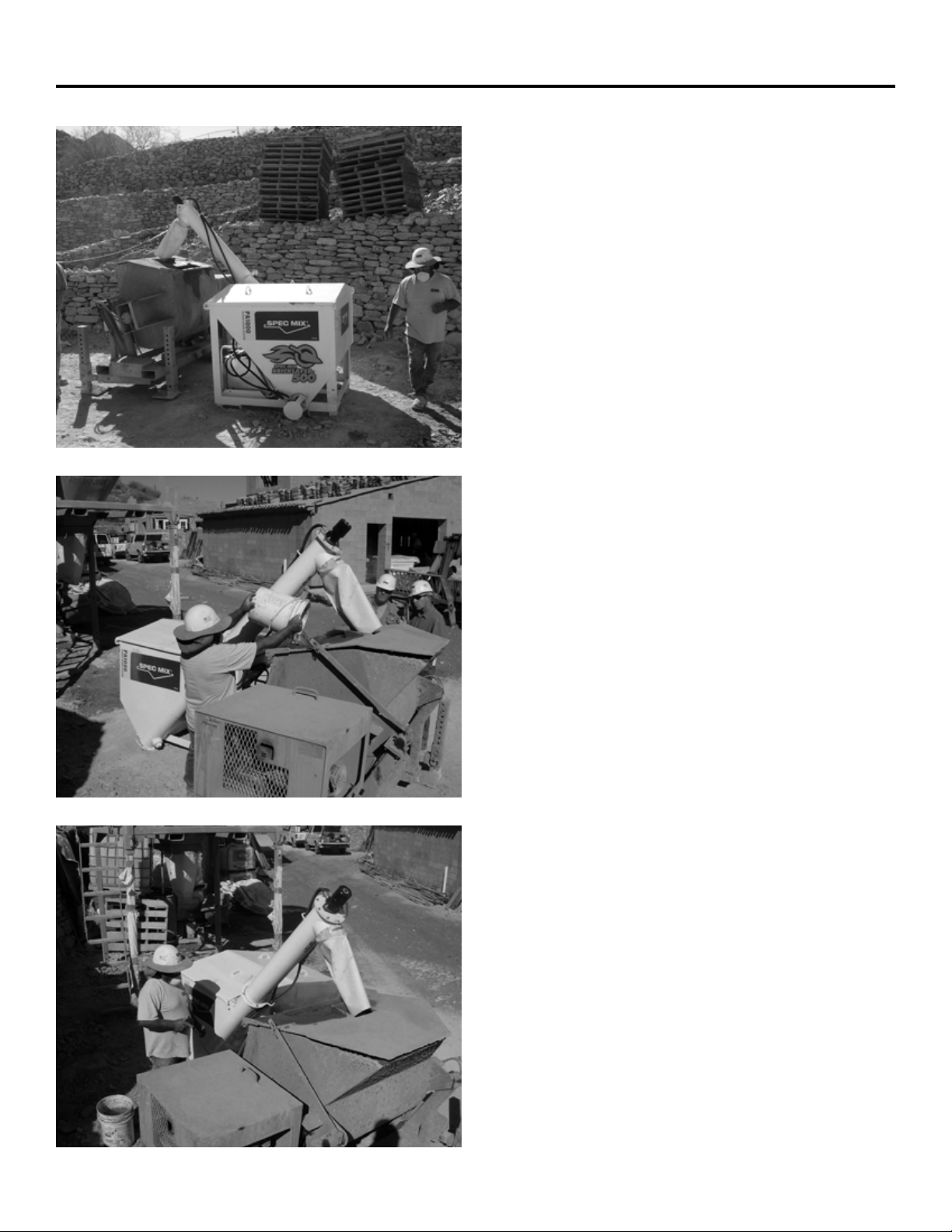
The PA (Power Auger) systems are a low profile, gas or electric powered hydraulic auger dispensing
material delivery system specifically engineered to increase a contractor’s efficiency, flexibility and
above all, safety. To ensure that a safe working environment is provided to all individuals who are
operating or have contact with SPEC MIX equipment, please abide by the following safety and
operation procedures for working with SPEC MIX PA systems and bulk bags.
Since safety is everyone’s responsibility, we ask that you become familiar with these procedures
yourself, and make sure that everyone operating or having any contact with SPEC MIX PA systems
and bulk bags be familiar with and implement, the following procedures as well.
It is everyone’s responsibility to be aware of the necessary precautions that must be taken to ensure
that laborers are provided with a safe working environment; and that they implement safe handling
and operating procedures for their own safety as well as others.
NOTE: These warnings do not constitute all possible safety hazards encountered in the use of
such products on a construction site. All applicable OHSA regulations must be followed in the
setup, relocation, cleaning, or use of the silo and product.

4
PA SYSTEMS SPECIFICATIONS
PA1000
PA4000
FOOTPRINT 4 ft X 5 ft HYDRAULIC POWER PACK 2.8K7V
CAPACITY 40 cubic feet MOTOR OPTIONS 14 hp GAS MOTOR
WEIGHT EMPTY 1,100 lb 7.5 hp ELECTRIC MOTOR (220V, 30AMP, SINGLE PHASE)
WEIGHT FULL UP TO 4,100 lb
SHIPPING SIZE 5 ft X 7 ft 6 in HYDRAULIC OIL TANK 6 gallon CAPACITY
SHIPPING HEIGHTS 4 ft 2 in COLLAPSED OIL OUTPUT 14 hp - 2,500 psi, 6 GPM
HOPPER HEIGHTS LOW SETTING: 4 ft 2 in
HIGH SETTING: 5 ft 2 in MIX OUTPUT 14 hp - 3,000 lb PER 7 MINUTES
AUGER DISPENSING HEIGHTS LOW SETTING: 5 ft
HIGH SETTING: 6 ft FORKLIFT REQUIREMENTS 4,500 lb
FOOTPRINT 7 ft 3 in X 6 ft 3 in HYDRAULIC POWER PACK 2.8K7V
CAPACITY 150 cubic feet MOTOR OPTIONS 14 hp GAS MOTOR
WEIGHT EMPTY 2,000 lb 7.5 hp ELECTRIC MOTOR (220V, 30AMP, SINGLE PHASE)
WEIGHT FULL UP TO 17,000 lb
SHIPPING SIZE 7 ft 8 in X 8 ft 6 in HYDRAULIC OIL TANK 6 gallon CAPACITY
SHIPPING HEIGHTS 6 ft 3 in COLLAPSED OIL OUTPUT 14 hp - 2,500 psi 6 GPM
HOPPER HEIGHTS LOW SETTING: 6 ft 3 in
HIGH SETTING: 7 ft 7 in MIX OUTPUT 14 hp - 3,000 lb PER 7 MINUTES
AUGER DISPENSING HEIGHTS LOW SETTING: 5 ft
HIGH SETTING: 6 ft 4 in FORKLIFT REQUIREMENTS 4,500 lb

5
TRANSPORTING SPEC MIX®PA SYSTEMS ON ROADWAYS
1. Inspect SPEC MIX PA system to make sure that it
has been emptied.
WARNING: Do not enter the interior of the PA system
hopper for any inspection or maintenance. If
absolutely necessary, turn off the PA system and
perform lockout procedures. All personnel must
follow confined space entry procedures (OSHA).
2. Make sure the gas or electric power pack is
securely locked or bolted into its place.
3. Secure top hatch handle with bolt and nut or lock-
pin.
4. To lower the PA system (PA4000), slightly raise the
system and remove leg pins & hitch pins from legs.
Lower PA system then secure legs in collapsed
position with leg pins.
5. Once lowered to the transportation mode, re-install
leg pins and hitch pins to their original position to
secure PA system’s legs.
6. If the terrain the PA system is being
transferred over is rough and uneven, secure a third
contact point between PA unit and forklift using
chain or strap with minimum tensile strength of
5,000 pounds live working load.
7. Slowly and carefully load the PA system onto the
trailer following accepted U.S. DOT procedures.
8. Secure PA system to the trailer using DOT
approved chains or straps and ratchets with a
minimum of 5,000 pounds tensile strength per
ratchet.
9. Remove any debris or material from PA system or
trailer bed before traveling.

6
ASSEMBLING SPEC MIX®PA SYSTEMS
1. Select a position on the jobsite where the ground
is dry, compacted, level and stable.
NOTE: To ensure the stability of the PA system, dry,
compacted, level ground MUST be available
for set up, or the unit should NOT be erected or
used.
2. Softer soil will require the use of either footings or
concrete pads of 24 x 24 x 6 inches of reinforced
concrete with a minimum compressive strength
of 3,500 psi.
3. Foot pads should be constructed of three
separate pieces of 24 x 24 inch treated plywood
that are ¾ inch thick and laminated together with
screws or of 24 x 24 x 1 inch steel pads. Discard
footpads when punctured. Each PA system
requires four footpads.
NOTE: A proper capacity forklift must be utilized to
lift the standard weights of the PA system and
material being used. (See PA specifications on
Page 3).
4. If the terrain the PA system is being transferred
over is rough and uneven, secure a third contact
point between PA unit and forklift using chain
or strap with minimum tensile strength of 5,000
pounds live working load.
5. Slowly lift and recline forklift position while
making sure no objects or people are in the way.
6. Place the PA system on the best suited location
on the project site.
7. By slightly raising the PA system, remove all four
leg pins allowing silo legs to telescope to full
adjustment.
WARNING: Keep legs, feet and hands clear of PA
system legs as they are lowered.

7
ASSEMBLING SPEC MIX®PA SYSTEMS
8. Raise tower to desired height until holes in
PA system leg match holes in receiver tube
assembly.
9. Secure PA system by inserting all four leg pins
at the desired height, then insert the safety hitch
pins in the holes of the four leg pins to lock the
leg pins in place.
10. Re-insert leg pin through receiver tube and leg
assembly while standing outside of the perimeter
of PA system.

8
STARTING UP & INSPECTING SPEC MIX®PA SYSTEMS
NOTE: It is very important to follow the proper
start-up and inspection procedures for the
SPEC MIX PA systems to ensure safe, reliable
and efficient operation.
1. With the PA system turned off and locked out,
check material flow basket and both augers for
positioning, obstructions or defects.
2. Connect Hydraulic Hoses: Verify that the
hydraulic hoses are coupled into position and
connected properly to the valves on the power
pack.
3. Filling the Hydraulic Oil Reservoir Tank: Open
the cap on the hydraulic oil tank and ensure
the tank is filled with 5 gallons of standard
hydraulic oil. If not, add the appropriate
amount of hydraulic oil. Close the cap on the
tank, run the unit and check the oil level again.
Top off hydraulic oil until a full reading is taken
on the dipstick. Use heavy weight hydraulic
oil in the summer (hot weather conditions) and
light weight hydraulic oil in the winter (cold
weather conditions). Change hydraulic oil
every 500 hours of use or with the change in
seasons. Always change the hydraulic oil filter
when changing hydraulic oil.
4. Filling & Checking Engine Oil: Fill the motor
oil reservoir with 5W-30 motor oil until a full
reading is achieved on the motor oil dipstick.
Change the motor oil after the first 20 hours of
operation and then after every hundred hours
of operation. The run time on the motor can be
located in the run time timer.
5. Filling Gas Engine: Fill the gas reservoir on the
motor with UNLEADED gasoline only.

9
STARTING UP & INSPECTING SPEC MIX®PA SYSTEMS
6. Greasing Auger Zerts: There are two grease
zerts on each PA unit. One is at the lower
bearing of the discharge auger opposite the
hydraulic motor and the other is on the end
of the bottom auger opposite the hydraulic
motor. Grease before use and then grease on a
weekly basis.
7. Connecting Battery: Connect the red wire to
the positive connection and the black wire to
the negative connection on the battery. If the
unit does not turn over when turning the key,
replace the battery.
8. Adjusting the Hydraulic Pressure: The hydraulic
pressure comes preset; however, the pressure
may be adjusted up or down on the unit. To
adjust the pressure, locate the valve mounted
on the hydraulic oil tank of the power pack.
Using an Allen wrench, remove the cap at the
rear of the valve. Then insert an Allen wrench
into the cap and turn clockwise to increase
pressure or counterclockwise to decrease
pressure.
IMPORTANT NOTE: The hydraulic pressure
should rarely, if ever, need adjustment. Contact
your local representative prior to adjustment.
Adjustment should be done by a qualified
mechanic only. If the PA System is not
dispensing material or appears to be jammed
up, contact your local supplier.
9. Prior to loading the PA system, turn it on to
ensure proper function while it is empty. Make
sure the fuel switch is in the “On” position.
Open the choke, if necessary. Position the
throttle to a low/medium position. Turn the
electric ignition key to start the motor. Close
the choke upon ignition. Slowly increase the
throttle to an operating level.
10. Use the corded auger switch to engage the
augers. Make sure the augers are turning the
appropriate direction to dispense material.
Turn off the motor by turning the key to the off
position prior to loading the PA system.

10
LOADING SPEC MIX®PA SYSTEMS
1. While standing on the ground, slide the outer
plastic cover down to the pallet level of the
material bulk bag. At this time, inspect the overall
condition of the bulk bag giving special attention
to the bag’s lifting loops. Check for fraying on
both sides. If the strap appears stressed, set the
bag and pallet aside for replacement and recover
to protect the material inside.
2. Save the product identification card or batch
ticket located inside the plastic cover. This
will verify the product delivered matches the
product ordered, which may be useful during the
construction process.
3. Once the bag has passed the visual inspection,
insert the forklift forks through the four lifting
loops. The forks should easily slide to a position
where all four loops are on the forks as far as
possible. It is important the loops do not leave
this position before lift tension is applied.
4. To improve flow, open the top spout of bag.
5. From an area opposite the side of the silo safety
rail platform or wherever the silo loading operator
is stationed, carefully raise the bag to the silo
hatch. At no time should personnel be under
the suspended bulk bag. The forks should be
at a reclined position while raising the bag to a
distance of 3-4 feet above the loading hatch. The
bag can now be slowly lowered to a point where
the bottom of the drop spout is 4-6 inches above
the PA flow basket. Hand communication signals
should be used to indicate when the bag has
been lowered the appropriate distance.
WARNING: Do not allow the bag to rest on the top
of the PA system.
6. The laborer/operator can now climb the ladder to
the safety railed platform once the bag is in this
position.
WARNING: The person on the platform must
securely attach both safety chains across the
entry point when on the safety railed platform.

11
LOADING SPEC MIX®PA SYSTEMS
7. The design of the PA system and bags is such
that the material charging of the silo can be done
without accessing the PA system top.
WARNING: Stay off the top of the PA system. All
PA system loading is to be done from the safety
platform or ground only.
8. After the bag is positioned over the hatch, slide
the silo hatch open.
9. Using the SPEC MIX Safety Hook grasp and
pull the hitch pin closure or plastic closure pin
located on the outer tie on the bottom of the
bag. This will open the protective outer flap
encompassing the bag’s discharge chute.
10. With the same SPEC MIX hook, pull the tagline
on the inner chute tie downward allowing it to
unravel into the open PA hatch and dispense
material down into the unit. There will be two
separate bag ties to unlock with the safety hook.
WARNING: Product dust may be hazardous. SPEC
MIX contains Portland cement and lime, masonry
cement, mortar cement, additives, sand and/or
color pigment that may cause eye and/or skin
irritation. We advise anyone using our product to
wear a NIOSH-approved dust protection mask,
eye protection, gloves, and appropriate clothing
to help protect from possible injury. Wash hands
thoroughly after handling. In case of eye contact,
immediately flush with plenty of water for at least
15 minutes. Contact a physician immediately.
Keep out of the reach of children.
11. Repeat these exact procedures for each bag
emptied into the silo for charging.
REQUIRED EQUIPMENT
Hard Hat
Gloves
Safety Harness
Safety Goggles
Dust Mask Recommended
12
OPERATING SPEC MIX®PA SYSTEMS
1. Position mixer under the flexible boot on the end of
the discharge auger to facilitate dumping of mixed
product into mud box or tub.
2. Place discharge chute as close as possible to mixer
protective grate or orifice. The height of the PA system
can be raised or lowered to accommodate most any
mixer. See instructions “Assembling PA systems”.
3. Start the mechanical mixer or mixer-pump.
4. Introduce 2/3 of needed mixing water into mixer. Start
the PA system (see starting instructions in “Starting
up” section. Next, locate the corded auger switch
that controls the flow of SPEC MIX preblended
material into the mixer. This is on a cord that extends
from the power pack.
5. To start the flow of material, push the switch forward
or backward to allow a steady stream of material to
flow into the mixer.
NOTE: Do not leave the switch unattended while
charging the mixer.
6. Adjust mix as needed by adding either more water or
SPEC MIX in order to obtain a workable or optimal
consistency.
7. Mixing times are 4-5 minutes per batch unless
otherwise specified in the Product Data Sheet’s
mixing instruction section. Mix each batch fully
according to standards.
WARNING: Injurious to eyes, lungs. Causes skin
irritation. SPEC MIX contains portland cement and
lime, masonry cement, mortar cement, additives, sand
and/or color pigment.
8. Avoid eye contact, prolonged breathing of dust or
contact with skin. Recommended are appropriate eye
protection, gloves and the proper clothing to protect
from prolonged exposure.
9. Wash hands thoroughly after handling. In case of eye
contact, immediately flush with plenty of water for at
least 15 minutes and consult a physician. Protect from
prolonged exposure.
10. When finished using the PA system on the project or
before relocation, follow clean-out procedures. See
“Cleaning out the SPEC MIX PA system” in Relocating
PA system.

13
RELOCATING SPEC MIX®PA SYSTEMS
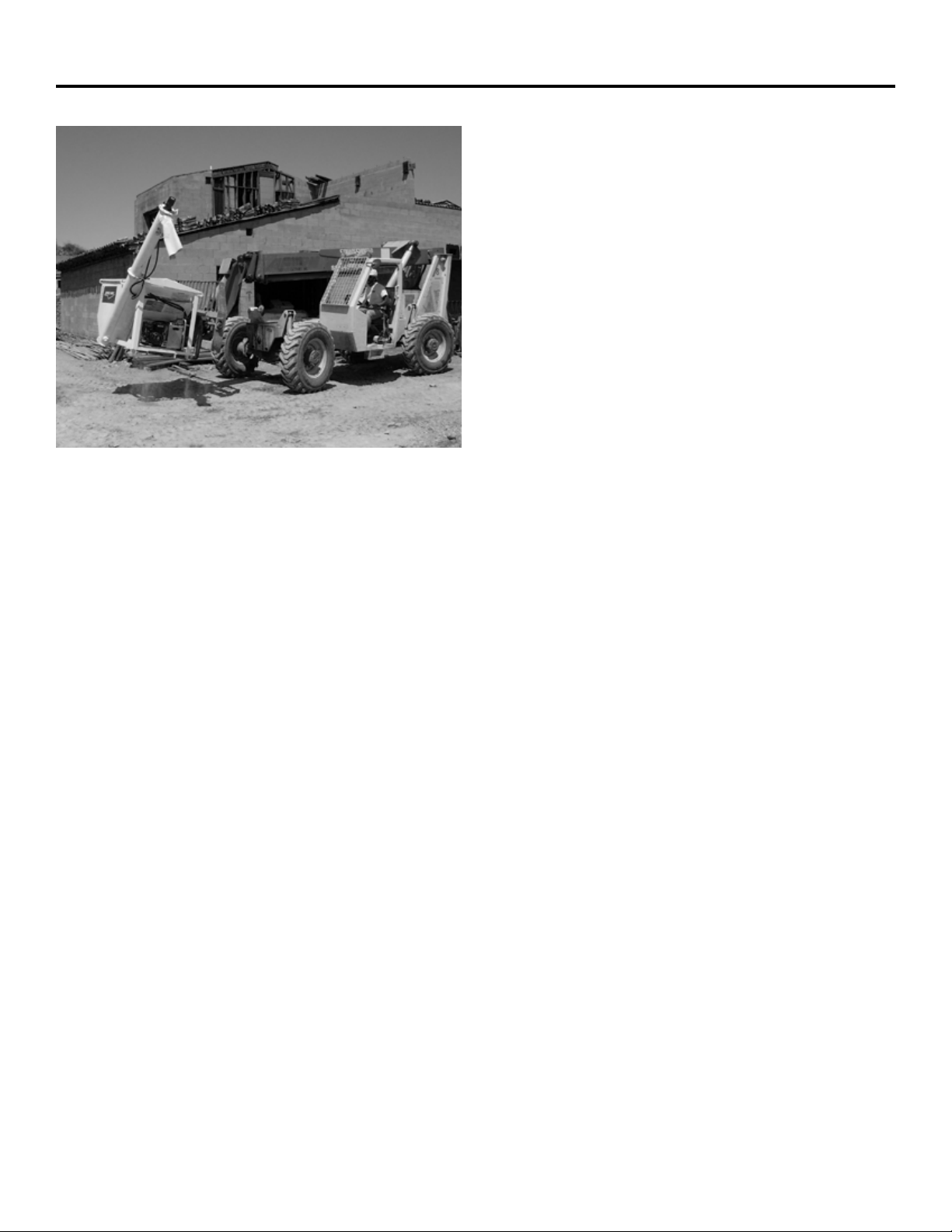
1. One of the many advantages of the SPEC
MIX PA system is the easy relocation of the
equipment. The ability to move the PA system
around the jobsite enables the forklift operator
to deliver mortar quickly and efficiently.
2. Select a position on the jobsite where ground
is dry, compacted, level and stable. (See
additional requirements in “ASSEMBLING SPEC
MIX PA systems.”)
3. Empty PA system as much as feasible or as
much as possible. (Material may be re-loaded
into an empty bag if necessary.)
4. Cleaning Out the SPEC MIX PA systems:
Run the PA system until material stops flowing
from the discharge auger and the interior of
the PA system appears to be reasonably free
of material. To completely clean the PA system
out, remove the threaded cap at the lower
end of the discharge auger. Allow the material
to drain until it stops, then engage the motor
and run the augers keeping hands out of the
cleanout hole. Place a container underneath the
cleanout to catch the material as it flows out.
Use or discard appropriately.
WARNING: Do not enter interior of the PA system
hopper for any inspection or maintenance. If
absolutely necessary, turn of the PA system and
perform lockout procedures. All personnel must
follow confined space entry procedures (OSHA).
NOTE: The PA1000 and PA4000 weigh
approximately 1,200 to 2,200 pounds,
respectively. See PA System specifications on
page 3 above for more specifics.
5. Remove mixer and any obstructions that may
hinder the freedom of movement, including any
hardened material around base of silo legs and
foot pads.
6. With the PA system empty and turned off, insert
the forklift forks into the PA unit’s fork tubes to
their full depth.
14
RELOCATING SPEC MIX®PA SYSTEMS
NOTE: A proper capacity forklift must be utilized
to lift the standard weights of the PA system
and material being used. See PA system
specifications above.
7. Slightly raise PA system and remove hitch pins
and leg pins from legs. Lower PA system while
manually raising ladder to avoid damage, if the
model is equipped with a ladder.
8. Once lowered to the transportation mode re-
install leg pins and hitch pins to their original
position.
9. If the terrain the PA system is being transferred
over is rough and uneven, secure a third contact
point between PA unit and forklift using chain
or strap with minimum tensile strength of 5,000
pounds live working load.
NOTE: The third contact point is necessary for
preventing the PA system from sliding off the
forklift forks during any jobsite transportation.
10. Slowly transport PA system to new location.
11. Follow same guidelines for initial erection of PA
system paying note to soil conditions as before.
12. Re-charge PA system following the instructions
for Loading SPEC MIX Power Auger Systems.

15
MAINTENANCE OF SPEC MIX®PA SYSTEMS
1. Maintenance begins on the day the silo is delivered.
a. PA system should be coated with release agent as supplied by Arrow/Mag-nolin, ZEP, or other
manufacturer.
b. Make sure all warning signs and decals are in appropriate locations on PA system and work platform. If not,
contact your local rep.
c. Check power pack, ladders, legs, augers, discharge boots for all parts, alignment, and ease of operation.
d. Check all leg pins, hitch pins, cables, stabilizer nuts and bolts, hatches, and safety chains for ease of
operation and proper locations.
e. Upon silo erection at jobsite, cover legs with poly, form release agent or utilize another method to protect
leg assemblies, and foot pads from material collection.
2. Daily maintenance to be performed by contractor:
a. Keep top hatch free of excess material in order to facilitate ease of opening and closing.
b. Check safety chains for stress.
c. Check discharge chute for proper height rips or tears. Replace as needed.
d. Check to make sure all warning signs are visible and in their proper location.
e. Check to ensure that all non-skid tapes are in place.
f. Check to make sure that all handles, chains, leg pins, hitch pins, and cables are in place and not bent, cut
or damaged. If so, replace immediately.
g. Inspect PA legs for alignment, dents or bending. Replace PA system immediately if necessary.
h. Check PA system for plumb and level.
i. Check position of all four 24 x 24 inch foot pads.
3. Power Pack Daily/Weekly Maintenance:
a. Inspect and Clean air filter on motor after every day of use. Install new air filter if it is excessively dirty or
damaged.
b. Check hydraulic oil for proper level. Adjust as needed.
c. Check Motor oil on gas power pack for proper level. Adjust as needed.
d. Check grease zerts weekly and add grease as necessary.
4. Upon return to Distributor or SPEC MIX Licensee, check the following and correct or replace as needed.
a. All signs are clean and visible.
b. All safety chains and clasp are operational.
c. PA unit is clean and empty.
d. Discharge chute is not cut, torn or weathered.
e. Material flow basket is intact, clean and operational.
f. Legs are free of mortar build-up.
g. Top of PA unit is free of excessive mortar build-up.
h. Top hatch integrity is sound and free of defects, broken welds or supports and free of mortar build up.
NOTE: Damaged PA legs affecting the integrity of the PA system must be replaced immediately before PA set up or
any continued use.
NOTE: There is no replacement schedule for the hitch pins unless a manufacture defect is evident.
WARNING: Do not enter the interior of the PA system hopper for any inspection or maintenance. If absolutely
necessary, personnel must follow confined space entry procedures as outlined by OSHA.
SPEC MIX PA systems have undergone constant improvement since their inception. Some retrofit actions are
necessary to maintain the highest safety standards.

1-888-SPECMIX
PHONE
1230 EAGAN INDUSTRIAL RD., STE 160, EAGAN, MN 55121
FAX 651-454-5315 WWW.SPECMIX.COM
© 2021 SPEC MIX, INC.
This manual suits for next models
1
Other SPEC MIX Music Mixer manuals


