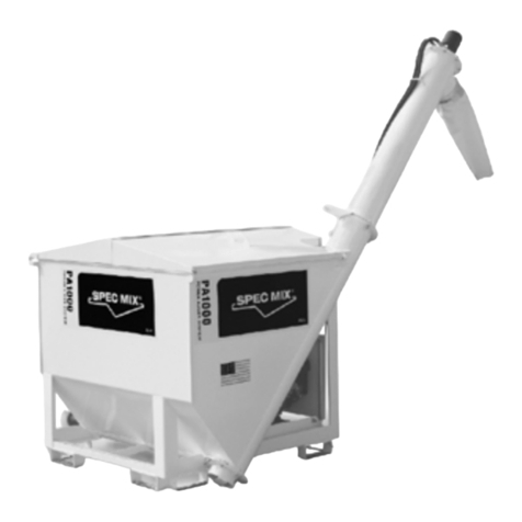
SPEC MIX D2W Use and care manual

D2W MIXING SYSTEM
GAS POWERED HYDRAULIC DRIVE
SILO DELIVERY
SYSTEMS
OPERATIONS
AND SAFETY
MANUAL

23
SETUP INSTALLATION GUIDETABLE OF CONTENTS
Setup Installation Guide.................................................................................................. 2-11
Cleaning and Maintenance SOP..................................................................................... 12-16
Water Stick Parts List........................................................................................................... 16
Mixer Assembly.............................................................................................................. 17-38
Hydraulic Drive End Parts List............................................................................................ 39
Electric Panel Parts List...................................................................................................... 40
Engine Assembly Parts List................................................................................................ 41
Hydraulic D2W Arrangement Parts List.............................................................................. 42
Electric Panel Schematic.................................................................................................... 43
Hydraulic Vibrators.......................................................................................................... 44-46
Gerotor Pump and Motor....................................................................................................... 47
Flow Control.......................................................................................................................... 48
Hydraulic Motor................................................................................................................ 49-50
Pressure Reducing Valve................................................................................................. 51-52
Solenoid Valve....................................................................................................................... 53
Bronze Y-Strainer.................................................................................................................. 54
NPT Globe Vave................................................................................................................ 55-56
Honda Engine Owner’s Manual....................................................................................... 57-76
Water Sump Pump............................................................................................................77-83
S16W Alternator............................................................................................................... 84-99
Leg Drawing for Drilling...................................................................................................... 100
SPEC MIX D2W GAS POWERED HYDRAULIC DRIVE Installation:
Vibrator installation:
Vibrator mounts on a divided piece of fork channel stitch welded to the silo as shown on the SPEC
MIX literature. Do not full weld the channel. Weld on about 1 foot above the rain skirt. Drill a
proper bolt hole pattern into the channel to receive the vibrator. A vibrator mount with predrilled
holes to receive the SPEC MIX D2W GAS POWERED HYDRAULIC DRIVE vibrator is available from
SPEC MIX Inc.
Silo Leg Preparation:
Remove standard legs from SPEC MIX silo and drill additional leg pin holes into the silo legs as laid
out in the SPEC MIX D2W GAS POWERED HYDRAULIC DRIVE Silo Leg diagram to allow for lower pin
positions. Leg pin hole diameter should be consistent with existing holes. Pre-drilled legs are
available from SPEC MIX Inc.
D2W GAS POWERED HYDRAULIC DRIVE Auger Installation:
1. Chose a 1998 or newer silo that has a 18” swivel gate on it and a round (not square) opening
at the base of the silo.
2. Remove the slide gate.
3. Keep the 4 swivel plates and 8 bolts that were previously installed on the flange of the silo.
4. Make sure that the transition cone is bolted to the D2W GAS POWERED HYDRAULIC DRIVE
above its gate and raise the auger up to the silo flange. Line it up to the silo opening and the
swivel plates. Bolt the swivel plates to the transition cone using the 8 bolts that were
previously installed. Make sure to use lock nuts.
5. Grease the slide plates with a grease gun at the 4 zerts.
6. D2W GAS POWERED HYDRAULIC DRIVE should rotate cleanly side to side from the bottom of
silo cone.
7. Chose a 1998 or newer silo that has a 18” swivel gate on it and a round (not square) opening
at the base of the silo.
Auger/Mixing Shaft Set-up:
1. For 8 bulk bags per hour, install full pitch screw.
2. For 3.5 bulk bags per hour, install ½ pitch screw.
D2W GAS POWERED HYDRAULIC DRIVE Panel Installation:

45
SETUP INSTALLATION GUIDE
SETUP INSTALLATION GUIDE
1. Hang both the electric and water pump panel on the cross bar that runs from leg to leg of the
silo on the side that is under the loading platform. Tensioning bolts must be retracted and
locking pins must removed prior to hanging.
2. Position the water pump panel closest to the discharge chute of the D2W GAS POWERED
HYDRAULIC DRIVE.
3. Tighten the panels to the silo cross bar using the tensioning bolts.
4. The panels can be adjusted up and down on the mounting hooks by adjusting the tensioning
bolts at the back of the panel to a comfortable height for the operator.
5. Slide the locking pins under into the holes in the mounting bracket under the crossbar of the
silo. I padlock can be placed in these pins to lock the panel to the silo. A second set of pad
locks can be placed in the hole at the bottom of the mounting hook so the panels cannot be
slid off the mounting hooks.
6. Connect the water line from the port on the mixing auger to the exit port at the top of the
water panel. Run the extra slack in the water line up over the rain skirt of the silo and coil the
slack. Do not allow the water line to kink at its entry into the auger.
7. Connect all plugs from the auger to the electric panel, vibrator to electric panel and water
pump to electric panel. The plugs all have different ends and can only plug in one way.
Additionally, there are tags under the electric panel telling which plug goes where. Finally, the
plugs are twist lock, so make sure that they are plugged in tight and twisted.
8. Have the on-site electrician verify power into the D2W GAS POWERED HYDRAULIC DRIVE. We
need 250 V, 50 Amp power at the electric panel, not at the electric panel on site or after it
moves down the power cord. The cord needs to be 8 gauge or 6 gauge if making very long
runs (100ft+). A plug end is supplied from the factory for the contractors extension cord that
will need to be wired by the onsite electrician to the 8 or 6 gauge cord.
9. Panel can be accessed with a standard flat screwdriver or a like tool.
Water Supply:
The D2W GAS POWERED HYDRAULIC DRIVE can either be connected to pressurized water or can
pull standing water from a tank that is 150 gallons or larger.
Pressurized Water Source:
1. If pulling water from a Hydrant or water tap on a building, connect the water line directly to
the water in port on the lower right of the water panel. There is an adaptor that comes with
the pump panel that has a King or Chicago fitting on one side and a ¾” hose thread on the
other for receiving the water hose. Connect King fitting to king fitting.
2. It is helpful to use large diameter water line when possible. We suggest 1” line with ¾” thread
ends. This will promote good water volume going into the machine. Smaller diameter hoses
lose volume and pressure especially if the hose is run a long way from the source. The hose
also must be protected and dedicated. Anytime that a forklift or vehicle runs over the hose,
water volume will be reduced going into the mixing chamber changing the consistency of the
material. Also, if the water line is not dedicated, anytime that another hose is connected and
used in series the volume of water entering the mixing chamber will be affected which will
change the consistency of the material exiting the D2W GAS POWERED HYDRAULIC DRIVE.
3. The water pressure should be checked at the pump panel. There is a pressure gauge below
the water adjustment valve. Pressure should be between 30 psi and 90 psi. High pressures are
possible, especially when pulling water directly from a hydrant. If the pressure is in excess of
100 psi, a pressure regulator needs to be added at the hydrant by the on-site plumber to
reduce the pressure. Water volume is needed, not high pressure. If the pressure is too high it
can cause excessive splashing inside the mixing chamber which will lead to the auger
potentially getting mortar stuck around it at the transition which will affect the mixing of the
material.
4. There is a valve above the water in port with hose thread on it. It can have a hose attached to
it only when pulling pressurized water and can be used for cleaning of mortar tubs, tools, etc.
It is important that the contractor only use this hose when the D2W GAS POWERED
HYDRAULIC DRIVE is not running. If used when the D2W GAS POWERED HYDRAULIC DRIVE is
running, the water going to the mixing chamber will be reduced causing the mix to be stiffer
than expected when exiting the D2W GAS POWERED HYDRAULIC DRIVE.
Standing Water Source:
The SPEC MIX D2W GAS POWERED HYDRAULIC DRIVE can run using a standing water source
from a tank with its water pump panel.
1. To pump water, attach the siphoning hose to the water inlet port of on the bottom right side
water pump panel.
2. Check the strainer at the end of the siphoning hose to make sure that it is free and clear of
any dirt or debris. Inside the strainer is a valve. Check this valve to make sure that it is
functioning properly.
3. The siphon hoes must be primed before turning the pump on. To prime, open the valve above
the water inlet port and fill the siphon hose with water. Once the hose is completely full of
water, shut the valve.

67
SETUP INSTALLATION GUIDE SETUP INSTALLATION GUIDE
4. When siphoning water, make sure to use a large standing water source. A 55 gallon drum is
too small and will run out of water quickly causing a loss of prime to the hose. A 150 gallon or
greater container is recommended.
5. At the end of each day, empty all water from the water pump panel by first shutting off any
pressurized water source and then opening the water exit valves at the bottom of the panel.
Note: Always protect from freezing. Water freezes at 32 degrees. In cold weather, the silo system
should be enclosed and heated. Water should be heated. If the enclosure is not heated overnight
or through a weekend, the water pump panel should be removed from the silo and placed in an
area that will have heat. Make sure that the hose from the water pump panel to the mixing
chamber is also free of water at the end of the day in freezing weather.
SPEC MIX D2W Operation:
Electric Panel Operation:
1. Turn on the main power switch located at the top, center of the panel. When turned on, the
power on indicator should illuminate.
2. On the lower right of the panel is the vibrator control switch. Turn the vibrator switch on
when normally using the SPEC MIX D2W GAS POWERED HYDRAULIC DRIVE to keep product
feed constant.
3. Locate the operation switch and select either local or remote.
a. Remote – when remote operation is selected, use the remote control to operate.
Press the 1 button (left button) to turn on and the 2 button (right button) to turn off.
Range is approximately 300 ft.
b. Local – when local operation is selected, the remote will not work. Press the green run
button to turn on the SPEC MIX D2W GAS POWERED HYDRAULIC DRIVE and the red
stop button to stop the SPEC MIX D2W GAS POWERED HYDRAULIC DRIVE.
4. Locate the function selection switch which is labeled with 3 options; Clean, Mix and
Continuous. The clean option and its function is discussed below in the Cleaning Instructions
section. The remaining options allow the user to choose either a continuous mixing cycle
(continuous) or a timed batch mixing cycle (mix).
a. Continuous – when continuous mix is selected, the SPEC MIX D2W GAS POWERED
HYDRAULIC DRIVE will run until stopped by the user either at the panel or by remote.
b. Mix – when mix is selected, the SPEC MIX D2W GAS POWERED HYDRAULIC DRIVE will
run for a set period of time and shut off automatically. The length of run time can be
adjusted with the dial on the lower left of the control panel labeled “Fill Size”. When
you turn the Fill Size dial as far as it can go to the left, the SPEC MIX D2W GAS
POWERED HYDRAULIC DRIVE will run for 1 minute. When the Fill Size dial is turned as
far as it can go to the right, the SPEC MIX D2W GAS POWERED HYDRAULIC DRIVE will
run for 10 minutes. Setting the Fill Size dial at 12 o’clock will run the SPEC MIX D2W
GAS POWERED HYDRAULIC DRIVE for approximately 5 minutes. This function lets the
user to pick the length of time that the SPEC MIX D2W GAS POWERED HYDRAULIC
DRIVE runs which allows the user to mix batches to the size of the container or
amount of material required to do the job.
c. Do not open the electrical panel door unless the fault indicator is illuminated (Red
Light). If the SPEC MIX D2W GAS POWERED HYDRAULIC DRIVE is not operating
properly but the fault light is not illuminated, it is likely that the problem is not with
the electric panel.
Cleaning Instructions:
Daily Cleaning Procedure:
1. Shut off the product flow by closing the gate above the SPEC MIX D2W GAS POWERED
HYDRAULIC DRIVE auger. To do this, pull the handle to the closed position. To ensure that the
gate is closed, look at the rod that goes through the gate and exits opposite the handle. It has
a line scored on it that matches the position or direction of the gate. Make sure that this is
horizontal when cleaning the unit.
2. Once the silo gate is closed, return to the control panel. Locate the mixing cycle indicator
(Clean - Mix - Cont) switch in the center of the panel. Turn the switch to the clean cycle
position.
3. Place a tub or container at the bottom of the D2W discharge and Start the SPEC MIX D2W GAS
POWERED HYDRAULIC DRIVE either at the panel or from the remote by pressing 1.
4. The SPEC MIX D2W GAS POWERED HYDRAULIC DRIVE will run for approximately 2 minutes
allowing water to flush out the mixing chamber and into the container placed at the bottom.
The paddles and mixing chamber are made out of a specialized plastic that resists
cementitious material sticking to it.
Note: If the SPEC MIX D2W GAS POWERED HYDRAULIC DRIVE is sitting between batches for an
extended period of time, please run a clean out cycle to keep the mixing chamber clean.
Weekly Cleaning Procedure:
1. Unplug the main power into the SPEC MIX D2W GAS POWERED HYDRAULIC DRIVE.

89
SETUP INSTALLATION GUIDE SETUP INSTALLATION GUIDE
2. Using a 17mm wrench or socket, remove the 3 nuts around the edge of the discharge
chute.
3. Remove the mixing auger by pulling it out of the mixing chamber.
4. Inspect the mixing auger and scrape any build up material from the shaft, paddles or
screw of the mixing auger.
5. Locate the clean out door below the dry product chamber of the mixing auger.
6. Using a large adjustable wrench or large channel locks, loosen the bolt that holds the
clean out door in place.
7. Remove the positioning bar and carefully remove the clean out door.
8. Using a brush and margin trowel, clean all dry product out of the dry product chamber.
Make sure to clean out the auger receiving collar at the rear of the mixing chamber.
9. Replace the clean out door, slide the locking bar in place and tighten the bolt under the
dry product chamber.
10. Slide the mixing auger back into the mixing chamber. Make sure to push the mixing auger
far enough into the mixing chamber to reach the auger receiving collar. Once the mixing
auger has reached the back of the mixing chamber, slowly rotate the auger until it slides
into the receiving collar. When properly inserted into the receiving collar, the last mixing
tool (the wiper) will be inside the end of the mixing chamber about ¼”.
11. Replace the SPEC MIX D2W GAS POWERED HYDRAULIC DRIVE chute, lining up the three
bolts with the bolt holes on the chute. The mixing auger slides through the hole in the
center of the chute.
Note: Cleaning out the dry product chamber and inspecting the auger weekly is a critical step
in the maintenance process for this equipment. Failure to clean out the dry product chamber
can cause premature wear and tear in the product conveying auger section if foreign objects
get into the chamber. The mixing auger itself can occasionally get build up of product,
especially where the product transitions from dry to wet material.
Trouble Shooting:
Problem: The SPEC MIX D2W GAS POWERED HYDRAULIC DRIVE will not turn on.
1. Check the main power coming into the electric panel. The power should be 250 volt, 50 amp
service. It is important that this is checked at the machine, not at the panel. Make sure that
there are no tears in the protective coating on the power cord and that it is not laying in
standing water.
2. Check to make sure that the plugs are all connected properly. The plug ends used on the SPEC
MIX D2W GAS POWERED HYDRAULIC DRIVE are waterproof, twist lock plugs. They need to be
connected tight and twist locked in place. The connection is very tight.
3. Check the wiring to make sure that the wires at the panel and in the plug head are connected
properly.
Problem: The SPEC MIX D2W GAS POWERED HYDRAULIC DRIVE is not producing consistent
product, the mix is too wet and then too dry.
1. Make sure there is product in the silo. If not full, load the silo to capacity.
2. If using pressurized water (not siphoning water) check the water source to make sure that it
produces consistent volume into the pump panel. This can easily be checked by running the
machine and watching the flow meter. If the float is moving during operation, the water
coming into the machine is not consistent. This can be due to others pulling water from the
same source on the jobsite or even the same waterline in a community. It can also be due to
the water line being run over by traffic on site. To remedy, go to a larger hose (1” line is
recommended) and protect the water line from being run over on site. If this does not remedy
the issue, switch to a large standing water source and siphon water into the water pump
panel.
3. Check the hose for any kinks. This is especially important for the line going from the water
pump panel to the mixing chamber. To keep this line from kinking, run the water hose up over
the fork pockets of the silo and coil to pick up any slack.
4. Make sure that the product shut off gate is completely open. If the gate is not straight up and
down, bridging can occur causing surges in product. Check this by inspecting the grove in the
rod end opposite the product shut off handle at the transition between the silo and mixing
auger. The groove or line should be vertical.
5. Check to make sure that the vibrator is on and working properly. If the vibrator is not on,
check to make sure that the vibrator switch is set to on at the electric panel. Once it is on,
check to make that the vibrator runs for approximately 10 seconds on and then 10 seconds
off. To do this, run the SPEC MIX D2W GAS POWERED HYDRAULIC DRIVE and place your hand
on the vibrator housing. If the time frame is not 10 seconds on and 10 seconds off, contact
your local SPEC MIX sales representative. If the vibrator is not running at all, check the plug in
connections to make sure that it is properly twist locked into position and verify that the
vibrator plug is plugged into the right cord at the electric panel by looking at the labels under
the panel near the cord exits. If the vibrator is plugged in correctly and still does not run,
check the fault light to make sure it is not lit up red. If lit up red, open the electric panel door

10 11
SETUP INSTALLATION GUIDE SETUP INSTALLATION GUIDE
and flip the tripped breaker. If the fault light is not red, contact your local SPEC MIX sales
representative.
6. If the vibrator is functioning properly, it is possible to increase the vibration output by
adjusting the weights inside the vibrator. To do this, remove the large orange caps on either
side of the vibrator and adjust the weights out. A metric set of Allen wrenches are required
and this should be done by your local SPEC MIX representative. Make sure that the machine is
unplugged before making this adjustment.
Problem: The SPEC MIX D2W GAS POWERED HYDRAULIC DRIVE is producing material slower
and has become wetter, requiring a reduction in water.
1. Check the water supply to make sure that it is still on and that no one has also pulled water off
the same line. You need dedicated water for this equipment.
2. Check the mixing auger for build up. There may be build up on the auger flighting at the point
where the product transitions from dry product to wet product. This reduces the volume of
product being introduced into the mixing chamber which will in turn require less water to
produce material at the same flow.
Problem: The SPEC MIX D2W GAS POWERED HYDRAULIC DRIVE water pump panel is leaking
water inside the panel box at the impeller housing.
1. The panel has not been drained during weather that is too cold and has frozen. Thaw the
panel slowly in a heated area. Empty the pump panel of all water. Remove the pump itself and
open the impeller housing. Remove old seal gasket and replace with new seal gasket. Check
impeller for any damage.
2. Check the solenoid for any internal damage. If damaged, replace. Make sure to get the same
solenoid and coil. The coil must match the original unit for amps and voltage.
3. Check the flow meter for any damage. If cracked, replace.
Problem: Prime is lost when siphoning water.
1. Make sure that the standing water source is large. A 50 gallon drum is not big enough as the
water will only make a few batches. Low water levels can cause a loss of prime. A 150 gallon
or greater water source should be used.
2. Check the valve at the prime port to make sure that it is completely shut.
3. Check the valve in the strainer at the end of the siphoning hose and make sure that it is
properly functioning.
Problem: When mixing, smoke is visible at the end of the mixing auger and there is a burning
odor.
1. The mixing auger has been forced forward towards the discharge chute due to dry product
build up in the auger receiving collar at the rear of the dry powder chamber in the mixing
auger.
a. Run a clean out cycle.
b. Unplug the main power into the SPEC MIX D2W GAS POWERED HYDRAULIC DRIVE
electric panel.
c. Remove the discharge chute and remove the mixing auger.
d. Remove the clean out door under the dry product chamber section of the mixing
auger.
e. Using a margin trowel or scraper and brush, clean the entire dry product chamber.
Make sure to scrape and clean out the dry product build up in the auger receiving
collar located at the end of the mixing chamber.
Note: The only way that problem occurs is if the mixing auger is removed and inspected then
replaced without cleaning the dry product chamber as the auger will push dry product back into
the receiving collar when reinserting it if the dry product chamber is full. The dry product chamber
should always be empty when reinserting the mixing auger.
Problem: When D2W is started, material is dry coming out for the first 1-5 seconds.
1. Hose from water pump panel to mixing chamber may have lost water.
a. Check to make sure that hose from water pump panel to mixing chamber is
installed correctly.
b. Hose from the water pump panel to mixing chamber may be too long. Cut and
shorten the hose.
Problem: When D2W Motor stops running or runs slow.
1. D2W may be hooked up to inappropriate power supply which may cause the motor or
parts of the motor to burn out.
a. Check to make sure that there is 250V, 50 Amp power is at the D2W. Consult
with an electrician and replace motor if necessary.

12 13
CLEANING AND MAINTENANCE SOP CLEANING AND MAINTENANCE SOP
The following Standard Operating Procedure (SOP) is for maintaining the SPEC MIX D2W GAS POWERED
HYDRAULIC DRIVE when it is returned to the plant from a project to ensure that it is in good operating
condition and to aid sales in assessing damages to customers when appropriate.
Water Requirement:
• 250+ gallon tote (for siphoning water)
Tools Required:
• 2 - 17mm wrenches or ratchets
• Large adjustable wrench
• Hammer
• Scraper / chisel
• Stiff bristle brush
• Margin trowel
• Grease gun
• Volt / amp meter
D2W GAS POWERED HYDRAULIC DRIVE Auger Shaft Assembly Maintenance:
1. Close the material flow gate above the D2W GAS POWERED HYDRAULIC DRIVE auger at the
base of the silo cone.
2. Remove the inspection hatch at the underside of the dry powder
chamber of the D2W GAS POWERED HYDRAULIC DRIVE.
3. Remove the discharge chute at the end of the mixing auger.
4. Remove the auger shaft from the auger chamber.
5. Clean the mixing tools and auger flighting. Remove any build-up of
hardened material on the mixing shaft using a hammer, chisel and
stiff brush.
6. Replace any of the worn mixing attachments on the auger shaft.
Important: Always remember to replace the auger parts in the same order as they were
removed and in the same position and orientation. The dry material auger sections should
always be installed with the recessed end inserted first onto the mixing shaft first.
When the plastic dry material auger from the factory wears out, order and install a metal replacement
auger from SPEC MIX Inc..
Metal replacement augers are available in ½, ¾ and full pitches.
• The ½ pitch auger (3.5 bulk bags per hour) is always used for mortar mixing, Part # 12091FPSA.
• The ¾ pitch auger (5.5 bulk bags per hour) can be used for grout and has been effective for mixing
mortar but consistency would need to be verified locally, Part # 12093FPSA.
• The full pitch auger (7-8 bulk bags per hour) is only used for grout production and should not be
installed on a silo that is intended for mortar production, Part # 1209FPSA
7. Place a container under the D2W GAS POWERED HYDRAULIC DRIVE below the inspection hatch and
open the gate to allow the removal of any material that is still in the silo. Make sure to use the silo
hammer to vibrate any loose material hung up in the silo. Close the gate when the silo is clean and lock
it into place with the tension knob.
8. Remove and inspect the lump breaker. It is located inside the dry powder chamber at the receiver for
the mixing shaft. Inspect the lump breaker for wear and if it is bent, attempt to bend it straight again. If
it cannot be repaired or is worn to a point where the metal is sticking through the plastic, replace it.
9. Replace the repaired and cleaned mixing auger. Make sure that it is seated properly into the mixing
auger receiver in the dry powder chamber of the D2W GAS POWERED HYDRAULIC DRIVE. When
properly installed, the last mixing attachment (the wiper) should be recessed about a half inch into the
outer mixing chamber.
10. Replace the inspection hatch once you are sure that the mixing auger is properly installed.
11. Replace the discharge chute. Inspect the ceramic bushing in the center of the discharge chute and
replace it if cracked or worn.
12. Inspect the outer mixing chamber. If any cracks or wear holes are identified, replace. Do not attempt
to patch the outer mixing chamber.
13. Check the water inlet at the mixing chamber and remove any blockages.
14. Grease the four swivel plates at the connection of the silo and the gate for the SPEC MIX D2W GAS
POWERED HYDRAULIC DRIVE. Make sure that the D2W GAS POWERED HYDRAULIC DRIVE swivels freely.
15. Check to make sure that the handle on the gate is properly aligned so that the gate is shut
(horizontal) when in the closed position and open (vertical) when in the open position. This can be
checked by looking at the axel on the gate opposite the handle. There is a grove cut into the flush end of
the axel that runs in the same direction as the gate itself for reference.

14 15
CLEANING AND MAINTENANCE SOP CLEANING AND MAINTENANCE SOP
16. Check the plug end and power cord for any exposed wires or other issues that may cause the
equipment to not function properly.
Electric Panel Maintenance:
1. Check the mounting brackets to ensure that they are secure and all the tension bolts are properly
functioning.
2. Check all the plug ends to make sure that they are free of obstructions and properly twist-locked into
the appropriate matching plugs.
3. Remove any mortar build-up on the panel and insure that all the buttons and switches function
properly.
4. Inspect the male end of the main power plug that should have been returned by the contractor. If it
did not get returned from the jobsite, contact sales so they can retrieve or charge the contractor for a
replacement.
Water Stick Maintenance:
1. Check the mounting brackets to ensure that they are secure and all the tension bolts are properly
functioning.
2. Remove any mortar build-up on the stick.
3. Inspect the siphon hose for any holes or other wear issues that need correction. Remove the screen
on the foot valve and inspect the spring mechanism of the foot valve to make sure it is functioning
properly. If the siphon hose is missing upon return, contact sales immediately so they can retrieve or
charge the customer for a replacement.
4. Inspect the pressurized hose attachment for any signs of wear issues that need correction. If the
pressurized hose attachment is missing upon return, contact sales immediately so they can retrieve or
charge the customer for a replacement.
5. To drain disconnect the hose feeding the stick and the hose going to the mixing chamber
Maintenance Requiring Power to Check:
The following D2W GAS POWERED HYDRAULIC DRIVE maintenance items require the D2W GAS
POWERED HYDRAULIC DRIVE to be powered. To properly power the D2W GAS POWERED HYDRAULIC
DRIVE you must supply 250 to 230 volt, 50 amp single phase service to the equipment. If power is not
available, a generator with a minimum capability of producing of 20 kilowatts can be substituted. Use an
8 gauge, 3-wire power cord if the distance from the power source to the D2W GAS POWERED
HYDRAULIC DRIVE is 50 feet or less. If it is necessary to run a power cord over 50 feet from the power
source, use a 6 gauge, 3-wire power cord.
1. Start gas engine and ensure electric panel is turned on and set to manual
2. Connect the siphon hose to the water stick and insert it into a full water container that is at least 100
gallons.
Important: Do not use a pressurized water hose to test the D2W GAS POWERED HYDRAULIC
DRIVE as it will not allow you to properly diagnose water pump issues.
3. Turn on the main power switch and verify that the main power indicator illuminates. If the main
power indicator light does not illuminate, check the power source coming into the machine.
Important: The most common fault occurs when the contractor does not run a clean out on
the equipment leaving product in the mixing chamber, then attempts to run this equipment
with hardened material around the mixing auger. Make sure to check the mixing auger if the
fault light is illuminated.
4. Verify that the mixing auger is turning in the correct direction, clockwise when facing the auger from
the front of the discharge chute. If not, check the plug end to verify that it is properly twistlocked into
position. Then check the circuit breakers inside the panel for a tripped breaker. Refer to the V05 GAS
POWERED HYDRAULIC DRIVE manual for more information.
5. Turn the vibrator switch to on and verify that the vibrator switches on for approximately 10 seconds
and then off for approximately 10 seconds. If using the vibrator.
Important: These units will be shipped without the vibrator engaged and a phone call will
need to be made to activate it if it is needed.
6. Run the D2W GAS POWERED HYDRAULIC DRIVE in each of the mixing cycles to verify proper function
(Continuous, Mix and Clean).
7. Run the D2W GAS POWERED HYDRAULIC DRIVE and check the mix time selector to verify that it is
properly functioning. When the mix cycle indicator is set to mix, the mix timing knob should run the
D2W GAS POWERED HYDRAULIC DRIVE for approximately 1 minute when turned as far as it will go to
the left and for approximately 10 minutes when turned all the way to the right. At the end of these
cycles, the D2W GAS POWERED HYDRAULIC DRIVE will stop automatically.
8. Run the D2W GAS POWERED HYDRAULIC DRIVE in continuous mode to verify its function. The D2W
GAS POWERED HYDRAULIC DRIVE should run until it is shut off when the mix cycle indicator is set on this
mode.
9. Run the D2W GAS POWERED HYDRAULIC DRIVE in the clean mode to verify its function. When set to
clean, the D2W GAS POWERED HYDRAULIC DRIVE should run for approximately 2 minutes and then shut
off automatically.

16 17

18 19

20 21

22 23

24 25

26 27

28 29

30 31

32 33

34 35

36 37

38 39
1
1
2
2
3
3
4
4
A
A
B
B
PARTS LIST
DESCRIPTION
PART NUMBER
QTY
ITEM
PTEHD2W001motor mount plate
11
PTEHD2W002
plastic spacer
1
2
PTEHD2W003
removable plate
13
PTEHD2W004
spacer plate
14
PTEHD2W005hydraulic motor mount
15
PTEHD2W006
1-15/16 bore 4 bolt flange
bearing
26
PTEHD2W007
shaft
17
PTEHD2W008
FULL ASSEMBLY
lovejoy assembly 1 inch
L110
L110 Rubber spider 1.25
L110
18
PTEHD2W009hydraulic motor
1
9
9
5
8
6
6
6
7
2
4
1
9
5
8
6
1
4
3
6
7
2
HYDRAULIC DRIVE END
FOR MIXING AUGER
IMPORTANT
GREASE BEARINGS
EVERY 160 HOURS
Table of contents
Other SPEC MIX Music Mixer manuals
