SPEC TALKZONE User manual

TALKZONE
INS-0117 R7 09-24-2021
Assembly instructions
For Privacy Booth
Note: These instructions depict the TALK-R
configuration. Panels will be mirrored for the
TALK-L version

IMPORTANT SAFETY INSTRUCTIONS
When using an Talkzone Privacy Booth, basic precautions should always be followed, including the
following:
Read all instructions before using this product.
DANGER – To reduce the risk of electric shock:
1. Always unplug this furnishing from the electrical outlet before cleaning.
WARNING – To reduce the risk of burns, fire, electric shock, or injury to persons:
1. Unplug from outlet before putting on or taking off parts.
2. Close supervision is necessary when this product is used by, or near children, invalids, or disabled
persons.
3. Use this product only for its intended use as described in these instructions. Do not use attachments
not recommended by the manufacturer.
4. Never operate this product if it has a damaged cord or plug, if it is not working properly, if it has been
dropped or damaged, or dropped into water. Return the product to a service center for examination and
repair.
5. Keep the cord away from heated surfaces.
6. Never drop or insert any object into any opening.
8. Do not use outdoors.
9. Do not operate where aerosol (spray) products are being used or where oxygen is being
administered.
10. Max Table Load Rating is 11 lbs.
SAVE THESE INSTRUCTIONS
GROUNDING INSTRUCTIONS
:
This product is for use on a nominal 120-volt circuit and has a grounding plug that looks like
the plug illustrated below. Make sure that the product is connected to an outlet having the
same configuration as the plug. No adapter should be used with this product.

TalkZone Maintenance
Please note that the TalkZone booth requires periodic maintenance in order to remain in good working
condition.
NOTE – Unplug the booth/disconnect it from its power source before performing any maintenance
MONTHLY
1. Check the booth to ensure it is level and adjust as needed
2. Check the hinge bolts (3 top and 3 bottom) to ensure they are tight
DO NOT USE POWER TOOLS TO TIGHTEN, OVER TIGHTENING CAN CAUSE THE HINGE PLATE TO FAIL
3. Check the hinge plates on the outside of the booth for signs of damage
IF DAMAGE IS FOUND PLEASE CONTACT SPEC FURNITURE BEFORE THE BOOTH IS USED AGAIN
4. Check the door to ensure it is sitting square in in its frame with an even gap on the top and
bottom of the door – there should be at least 3/16” clearance between the bottom of the door and the
frame
5. Check the door for any signs of cracking or chipping
THE DOOR IS MADE FROM TEMPERED GLASS, IF CRACKS OR CHIPS ARE FOUND IT SHOULD BE
REPLACED IMMEDIATELY
6. Clear any debris off the inside of the door frame, paying close attention the bottom where dirt &
debris may collect
7. Wipe down the door gasket with a damp cloth to remove any dust/debris, check for tears in the
gasket at the same time
8. Inspect the fans from the back of the booth, if they appear to be collecting excessive amounts
of dust perform a clean out of the power trough as outlined under the yearly maintenance tasks below
9. Check thumb screws on the table to ensure they are all (qty 6) in place and tightened
10. Check thumbs screws on the troughs to ensure they are present (qty 4)
A

YEARLY
1. Perform monthly maintenance tasks 1-7 above
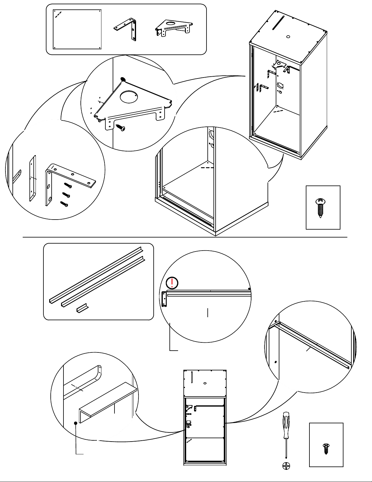
2. Remove the 6 thumb screws holding the table in place
3. Remove the table
4. Cover the table brackets with a soft material
TABLE BRACKETS HAVE SHARP CORNERS WHEN THE TABLE IS REMOVED, IT IS CRITICAL THAT
THEY BE COVERED UNTIL THE TABLE IS REINSTALLED
5. Remove the two thumb screws holding the lower trough in place
6. Allow the top of the lower trough to swing outward, then lift vertically to remove the trough from
the booth
7. Remove the two thumb screws holding the upper trough in plac
e
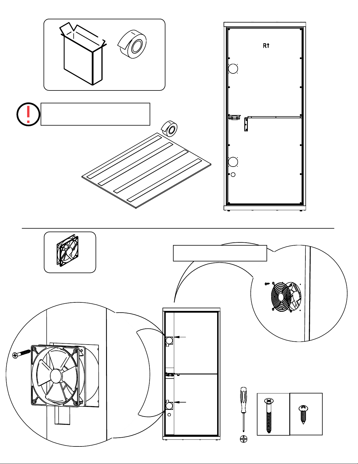
IT IS POSSIBLE THAT ONCE THE THUMB SCREWS ARE REMOVED THE TROUGH WILL DROP
SUDDENLY, TO PREVENT THIS HOLD THE BOTTOM OF THE TROUGH AS THE LAST THUMB SCREW
IS REMOVED
8. Allow the bottom of the upper trough to swing outward then pull it down to release it from the top
of the booth
9. Rest the upper trough face down on the covered table brackets
10. Using an air duster or other purpose made electronics cleaner blow the dust off of the power
module, infrared sensor, power splitter, upper and lower fans, surfaces of the troughs, and corner of the
booth
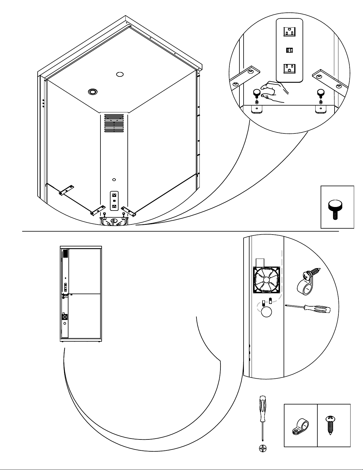
11. Check to ensure all plugs are securely connected
12. Check to ensure cables are neatly organized and secured and will not interfere with the fans
13. Check to ensure the fans are spinning freely
14. Check for any signs of over heating or damage to electrical components
IF ANY DAMAGE OR SIGNS OF OVERHEATING ARE FOUND PLEASE CONTACT SPEC FURNITURE
BEFORE THE BOOTH IS USED AGAIN, DO NOT RECONNECT IT TO A POWER SOURCE
15. Reinstall upper trough, being careful to not pinch any wires
16. Reinstall lower trough
17. Reinstall table
18. Reconnect the booth to its power source (plug or other) and test to ensure the sensor, light, and
fans are functioning B

#3, #2
x2 x2
x3
x1
83
1/8
"longaluminumchannelwithgasket
36
7/8
"longaluminumchannelwithgasket
29
1/2
"longaluminumangle
26
1/4
"longaluminumangle
3"longaluminumangle
x2
x1
x1
x1
x1
x1 x1
Non-hydraulicHinge
HydraulicHinge
5/32",
M3 & M5
x1
Note: These instructions depict the TALK-R configuration
Assembly time: Up to 3 hrs
#2, #1
x2
LightKitwithCord
i
x1

ACOUSTIC
PANELS
41.5
30.2
38.5
6.5
38.5
6.0
41.5
23.5
42.1
23.5
41.5
42.1
29.5
29.5
38.5
6.5
38.5
6.0
Top Panel
TALK-R Acoustic Panel: Installation Sequence
1
45
67
ii
42.1
30.2
Upper Rear Panel
2
Push out for light before
installing. (only remove
center cutout for adding
fire suppression)
2
1
3
3
4
6
5
8
7
9
10
11
8
9
10
11
Note: The ceiling panel has a centre cut-out that can
be used for sprinkler installation. The building and fire
marshal must be contacted before installation,
notifying that rooms are designed for a fire
protections pipe drop
.

ACOUSTIC
PANELS
42.1
30.2
38.5
6.5
Upper Rear Panel
38.5
6.0
41.5
23.5
42.1
23.5
41.5
42.1
29.5
29.5
38.5
6.5
38.5
6.0
Top Panel
TALK-L Acoustic Panels: Installation Sequence
1
2
345
6
7
Push out for light before
installing. (only remove
center cutout for adding
fire suppression)
iii
2
1
3
4
6
5
8
7
9
10
11
30.2 41.5
8
910
11
Note: The ceiling panel has a centre cut-out that can
be used for sprinkler installation. The building and fire
marshal must be contacted before installation,
notifying that rooms are designed for a fire
protections pipe drop
.

Do not over-tighten fasteners.
x28
HDW-0028
#12 x 7/8 Pan Wood Screw
x14
HDW-0790
Minifix Cam Zinc
x14
HDW-0791
Minifix Bolt - B34/5x8mm
x12
WOD-0113
Fluted Wood Dowel
x24
HDW-01100
1/4-20 - 70mm Hex Bolt
x28
HDW-0449
#6 -
1/2
" screw
x10
HDW-0449
#6 -
1/2
" screw
HDW-1099
Thumb screws
x4
GLD-0131
Slotted glides
x8
HDW-0729
#6 - 2 1/4 " screw
Note: Floor mounting hardware not provided by Spec
™.
HARDWARE
Note: These instructions depict the TALK-R
configuration. Panels will be mirrored for the
TALK-L version
x6
HDW-1100
10-32 x 3/4" Flat quad screw
x2x1
x2
PLT-0413
Threaded Hinge plate
x6
HDW-1110
#10 spacer washer
x6
PAK-0473
Black Cable Tie, 14.5" long
C
A
R
P
E
T
S
x2
ACT-2408
Nylon Cable clamp
iv
x2 x1
TALK-R TALK-L

2
1
1
x4
x7 x6
x2
Note: Do not over-tighten fasteners.
Note: These instructions depict the TALK-R
configuration. Panels will be mirrored for the
TALK-L version
5/32
"

4
3
2
x14
x2
Note: Ensure arrow is pointing outwards
Turn clockwise to
lock into place
Note: These instructions depict the TALK-R
configuration. Panels will be mirrored for the
TALK-L version

6
5
3
x4
x8
x2
x2
Note: These instructions depict the TALK-R
configuration. Panels will be mirrored for the
TALK-L version
5/32
"
5/32
"
Note: The ceiling panel has a centre cut-out that can
be used for sprinkler installation. The building and fire
marshal must be contacted before installation,
notifying that rooms are designed for a fire
protections pipe drop
.

8
4
7
x7 x6
Note: Do not over-tighten fasteners.
Note: Ensure arrows are pointing outwards before positioning
x2
Note: These instructions depict the TALK-R
configuration. Panels will be mirrored for the
TALK-L version

10
9
5
x2
x2
x4
x4
Turn clockwise to
lock into place
Note: These instructions depict the TALK-R
configuration. Panels will be mirrored for the
TALK-L version
5/32
"

12
11
6
x3+
!
x4
!
ADJUST GLIDES
TO LEVEL BEFORE
NEXT STEP

14
7
13
x2
x6
x2
x6
Note: Ensure the bulb seal is positioned facing out of the door way
Note: These instructions depict the TALK-R
configuration. Panels will be mirrored for the
TALK-L version

16
8
15
x8
x3
x17
BOTTOM VIEW OF
REAR PANEL
26 1/4"
29 1/2"
3"
USE THIS ORIENTATION
FLOOR
Install the back piece first
!

18
9
17
x8
ACOUSTIC
PANELS
Note: Ensure the panels are aligned properly before placing two sided tape
x2
INTAKE
FAN
EXHAUST
FAN
Note: These instructions depict the TALK-R configuration. Panels
will be mirrored for the TALK-L version
USE PAGE ii
(TALK-R)
or iii
(TALK-L)
FOR INSTALLATION SEQUENCE
!
x8
FAN GRILLS TO BE INSTALLED
ON BACKSIDE OF THE BOOTH
Note: Fan configuration: 1 faces
forward, 1 faces backward to achieve
air flow

20
10
19
PUSH CONNECTOR BACK
THROUGH THIS HOLE
TO PLUG INTO LIGHT
PULL WIRE THROUGH
THIS HOLE AND NEST
IN SLOT
SCREW IN LIGHT BRACKET
(SUPPLIED IN THE KIT)USING
SCREWS SUPPLIED IN THE KIT
PLUG IN LIGHT AND SECURE
LIGHT IN THE HOUSING
USE THE 2 SIDED TAPE TO
SECURE THE CORD OUT
OF SIGHT
LIGHT KIT
& CORD
PLUG 3-WAY SPLITTER
INTO SENSOR, THEN CLIP
INTO TROUGH &SECURE
WITH A ZIP TIE
ATTACH WITH THUMB SCREWS AND PLATES
SUPPLIED, WITH CORD ORIENTED AS SHOWN
SET SENSOR FOR 5 MINUNTES
& CONTROL SETTINGS

22
11
21 PLUG UNITS IN
TO 3-WAY SPLITTE
R
Note: These instructions depict the TALK-R
configuration. Panels will be mirrored for the
TALK-L version
Note: These are designed to fit tight. If too
snug, squeeze the hem with pliers.
Note: Ensure proper fan configuration

24
12
23
x2
Note: These instructions depict the TALK-R configuration. Panels
will be mirrored for the TALK-L version
x2 x2
Use the two clips to affix the
power supply cord to the
booth before feeding the
plug through the panel.
Please orient the clips as shown.
These are for strain relief
Table of contents
Other SPEC Indoor Furnishing manuals
Popular Indoor Furnishing manuals by other brands

CorLiving
CorLiving LFF-300-D manual

Lopas
Lopas Valsa 02 Assembly instructions

Next
Next SEVILLE 499546 manual

Great Little Trading
Great Little Trading Animal Stacking Box Mr. Fox Assembly instructions

Sensea
Sensea NEO manual

MANCHESTER WOOD
MANCHESTER WOOD Cherry Contemporary Media Stand Assembly instructions

modway
modway MOD-6119 Assembly instructions

MANCHESTER WOOD
MANCHESTER WOOD SHAKER ENTERTAINMENT CONSOLE Assembly instructions

BOBOCHIC
BOBOCHIC ZIRA Assembly instructions

Coopers of Stortford
Coopers of Stortford 8267 instructions

Forte
Forte SNWT12 Assembling Instruction

Rauch
Rauch Montana 30295.6610 Assembly instructions