SPECAVTOMATIKA DOKA User manual
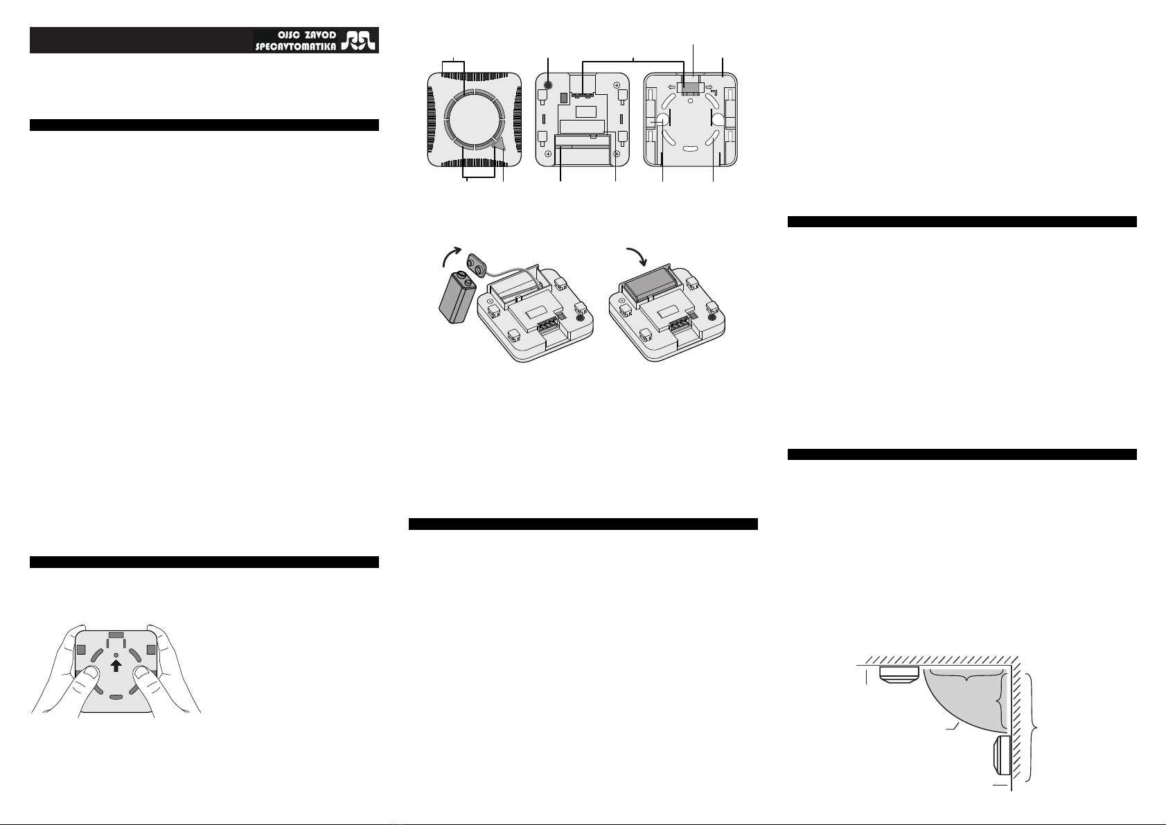
fixing holes
cable
channels
serial
number
PUSH НАЖАТЬ
1234
openings for
smoke inlet
light
indicator
"Test"
button
multi-connector base
numbers of contacts
of multi-connector
mechanism that blocks the
installation of the detector
in the base without a
battery
AUTONOMOUS FIRE SMOKE DETECTOR
IP 212-03K "DOKA - a"
Technical Instruction 01.408.00.000-01 TI (red.12.20.EN)
activation of any external device for fire alert;
continuous self-test of operability;
battery charge monitoring.
џ
џ
џ
џ
1. IMPORTANT INFORMATION
This document contains information of the operating principle, design and technical
characteristics of autonomous fire smoke detector IP 212-03K "DOKA - а" (hereinafter
referred as detector).
The document contains instructions necessary for correct installation, connection,
operation, technical maintenance activities, storage and product transportation. It also
contains the information that certify the manufacturer's warranty.
The detector meets all requirements of TU BY 100016872.097-2020, GOST R
53325-2012, Technical Regulations on Fire Safety Requirements, STB 11.16.08.
The operating principles and design solutions applied in "DOKA-a" detector are the
intellectual property of OJSC "ZAVOD SPECAVTOMATIKA".
The following abbreviations are used in this document:
APS - autonomous fire alarm;
IR - infrared;
NO - normally open;
ACU - alarm control unit.
Application
The detector "DOKA-a" schould be installed in enclosed spaces for continuous 24-hour
detection of fires accompanied by smoke, operating from a built-in 9V power supply element
(6F22 battery or similar).
"DOKA - a" provides:
џ automatic detection of fire in buildings and structures;
light and sound fire alert of people independently or as part of a group of detectors
united in the AFA system consisting of 2 to 40 "DOKA - a" detectors;
SAFETY
The design of the detector meets the general safety requirements of GOST 12.2.003
and does not contain elements that have a harmful effect on human health or the
environment.
According to the method of protecting a person from electric shock, the detector
belongs to products of Class III according to GOST 12.2.007.0 and does not have
internal or external electrical circuits with voltage above 42 V.
!
The "Fire" state sound signal is very loud. While pressing the “Test” button, keep
the detector at arm's length.
2.
DETECTOR INTRODUCTION
2.1. Open the package
! If the detector was in conditions of negative temperatures, keep it for at least 4 hours
at the temperature of the heated room.
2.2. Disconnect the detector from base and check the package contents:
* – 1 pcs. per 5 detectors allowed
** – upon agreement with the purchaser it is allowed not to deliver in the package
2.3. Familiarize yourself with the design of the detector
џ compare the serial number and date of manufacture on the case with the records in
your datasheet;
џ make sure that there are no visible mechanical damage (cracks, chips, dents);
џ make sure that the warranty seal is intact.
2.4. Connect the battery and place it in the battery compartment in the
detector housing
2.5.
Press and hold the "Test" button for at least 2 seconds
The detector must switch to the "Fire" state. Make sure that the volume of the
sound signal is loud enough and that it sounds without audible defects. The light
should flash simultaneously with the sound signal.
!
The "Fire" state sound signal is very loud. While pressing the “Test” button, keep
the detector at arm's length.
2.6.
After releasing the "Test" button, the detector must return to the
"Standby Mode" state
Make sure that the light indicator flashes once every 20-25 seconds after
switching to the "Standby Mode" state.
3. DESIGN AND OPERATING PRINCIPLE
The detector is an automatic electronic device with an optical sensor that signals
the appearance of smoke at the place of its installation.
The optical density of the medium inside the sensing chamber is analysed by
measuring the level of reflected IR radiation from the surface of the smoke particles
and then processing the received signal.
The response time of the detector to smoke depends on the fire conditions and
the properties of the burning materials.
If there is no smoke in the measuring chamber, the detector will be in the
"Standby Mode" state. There should be periodic single flashes of the light indicator
in red and no sound signals at all.
When smoke appears in the detector's sensing chamber, the detector goes into the "Fire" state.
The alarm is triggered by switching on the light and sound signals on the detector itself, issuing a
"Fire Alert" signal for other "DOKA - a" detectors as part of the AFA system and closing the
normally open built-in "Fire" relay. The detector remains in the "Fire" state until the end of
exposure to smoke and then switches to the "Standby Mode" state.
The detector is powered autonomously by a replaceable battery with a nominal
voltage of 9 volts. The detector provides electrical and mechanical protection
against incorrectly connected battery polarity. When the battery is low, the detector
generates a periodic light and sound signal.
The detector has a system for self-testing the performance of the optoelectronic
unit and the battery charge level.
If there is a complete loss of performance (or complete discharge of the battery),
any indication will be absent.
Forced testing of the "Fire" state is performed using the "Test" button.
The detector housing is made of impact resistant ABS plastic and forms a
protective shell.
A chamber with compartments is structurally made in the front part of the
housing to keep dust from getting inside the optical-electronic system.
The detector is shielded from static electricity and electromagnetic interference.
The base is used to install and connect the detector. The detector is
connected to the base by means of a detachable connection without using
any special tools. The detector is connected to external circuits via the
multi-connector according to the diagram (see section 5.2).
The multi-connector has four numbered contacts:
џ
"General" (4) and "NO" (3) - serve to transmit a fire signal by closing the NO
circuit for any external device (siren, Smart Home, GSM alarm system, etc.);
џ
"General" (4) and "AFA" (2) - serve to group "DOKA-a" detectors (AFA
system);
џ (1) - is a technological contact, any connections are prohibited.
4. INDICATION AND FUNCTIONS
"Standby Mode" state:
џ
The light indicator flashes every 20-25 seconds - the detector works properly.
џ
The light indicator flashes every 20-25 seconds simultaneously with a sound
signal - the detector is working correctly, but the battery is low to 7.5 V. The
power supply element has to be replaced!
"Fault" state:
џ
A short sound signal every 20-25 seconds at the same time as the light
indicator - optoelectronic unit is faulty. The detector must be taken in for
repair!
"Fire" state:
џ Intermittent (approximately 3 times per second) sound and light signals.
џ Closing of normally open relay contacts "Fire" ("NO" and "General").
џ
Appearance of voltage on the "General" and "AFA" contacts as a "Fire
Alert" signal for other detectors in the AFA system.
"Alert" state (only for detectors in the AFA system):
џ Intermittent (approximately 3 times per second) sound signal.
џ Closing of normally open relay contacts "Fire" ("NO" and "General").
"Test" state:
џ Similar to indication and functions in the "Fire" state.
SHIFT TO REMOVE
СДВИНУТЬ
ЧТОБЫ СНЯТЬ
Package contents includes:
џ Detector IP 212-03K "Doka - a"
џ Technical Instruction
џ Package
џ Power supply element 9V “6F22”
џ Multi-connector "DOKA - a"
џ Plug and screw
1
1*
1**
1**
2**
pcs.
1*
5. INSTALLATION AND CONNECTION
5.1. Selection of the detector installation location
It is not advisable to install the detector in areas where gases, vapours and aerosols
that can cause corrosion and false detectors are released.
Placement of the detector in premises must be carried out strictly in accordance with
the requirements of the design documentation (if any).
If you have purchased and are installing the detector on your own initiative, the
following recommendations must be taken into account:
џ
the main task of the detector is to sound an alarm when you do not control
the fire situation in your home. Therefore, install the detectors first in or near
bedrooms on the side of the most likely fire source (e.g. kitchen);
џ the most preferable location of the detector on the ceiling in the middle of the room;
џ it is prohibited to install the detector closer than 1 metre from ventilation openings;
џ
install the detector as far away as possible from sources of electromagnetic
interference (electrical wiring, fluorescent lamps, etc.) and infrared radiation
(heaters);
џ prevent water from entering or flowing on the side of the base;
џ it is permissible to install the detector on the wall.
Сeiling minimum 30cm
minimum 10 cm
maximum 39 cm
Installation is not
permitted in the
designated area
Wall
seal
Option 1:
Application of one "DOKA - a" detector as an independent smoke
detection and fire warning device.
Option 2:
The detectors are grouped (AFA system) by a two-wire line. One of
the detectors switches to the "Fire" state and generates the "Fire Alert" signal for the
other detectors. These detectors switch to the "Alert" state. The maximum number
of "DOKA - a" detectors in the AFA system is 40.
Option 3:
Install one "DOKA-a" detector and any siren with its own power
source. "DOKA - a" switches to the "Fire" state and closes with the built-in relay
"Fire" minus wire of the siren power supply circuit. The siren must operate at a
voltage of no more than 24 V and consume no more than 300 mA DC.
Option 4: The "DOKA-a" detector is connected to a normally open loop of any
automation (ACU, Smart Home system, GSM alarm system, etc.), which performs
the function of fire alert. "DOKA - a" switches to "Fire" and closes a normally open
loop. Upon a signal from the loop, the automatics will execute a fire alert. The
voltage in the loop must not exceed 24 V.
You can combine options 2, 3, 4 in any combination. The siren and/or ACU can
be connected to any of the detectors in the AFA system.
! When connecting, observe the polarity according to the diagrams below.
+
˗
ACU
5.2. Options for use To connect, disconnect the multi-connector as shown in the figure. Connect the
wires as shown in the diagram with a screwdriver.
After connecting insert the multi-connector into the base. Place the wires under the clips.
5.4. Functionality test
Press and hold the "Test" button until the detector enters the "Fire" state. Then release
the button. If you apply "DOKA - a" in options 2, 3, 4 (or any combination of these), make
sure that all the selected fire alarm modes are executed. After releasing the "Test" button,
the detector will return to the "Standby Mode" after a while.
6. TRANSPORTATION AND STORAGE
џ
The detectors must be transported in a packed form by any type of transport in
accordance with the rules for the carriage of goods in force for this type of
transport.
џ
Packed detectors during loading and unloading operations and transportation
must not be exposed to sharp shocks and precipitation.
џ
The method of laying and fixing of detectors on the vehicle must exclude their
movement.
џ Transportation conditions must comply with storage conditions 5 in accordance with GOST 15150.
џ
The detectors must be stored in packages in a heated and ventilated storage areas on
the racks at temperatures from +5 °C to +40 °C and relative humidity of not more
than 80% at 25 °C (storage conditions 1 in accordance with GOST 15150).
7. MANUFACTURER WARRANTY
џ
The manufacturer guarantees the compliance of the detectors with the
requirements of technical specifications, provided that the consumer meets the
conditions of transportation, storage, installation and operation.
џ
The warranty operation period is 24 months from the date of putting the detector into
operation. The warranty storage period is 12 months from the date of manufacture, provided
that the conditions of Section 6 are met.
џ
Detectors found to be in non-compliance with the requirements of technical
conditions during the warranty period shall be restored at the manufacturer's expense.
џ
Warranties apply to detectors that have no traces of mechanical impact
and the warranty seal has not been damaged.
8. DISPOSAL CONSIDERATIONS
At the end of its service life, the detector is disposed of in accordance with the
applicable nature protection legislation.
The detector contains no precious metals.
9. MAINTENANCE
џ
Maintenance of the detector during operation consists of cleaning the detector
components and checking their functionality.
џ
It is recommended to check the functionality of the detector approximately once
a month by triggering the detector with the "Test" button.
џ
In the event of false alarms, an unscheduled dust cleaning of the detector must
be carried out or it must be handed over for repair.
џ
If the detector generates a "Battery Discharge" sound signal, the detector must
be disconnected from the base, the battery replaced and the functionality checked.
Sensing chamber cleaning
џ
Try to blow through the smoke inlet openings for 1 minute with compressed air
on all sides (0.5 ... 3 kg/cm²).
џ If this does not result in positive results, clean the sensing chamber by
disassembling the detector according to instructions on www.dokasensors.by.
! After the maintenance and/or removal/installation of the detector, perform its testing.
!
When carrying out maintenance work, it must be ensured that the detectors are
protected from construction materials and dust.
max 3.5 mm
12. CERTIFICATE OF ACCEPTANCE
Autonomous fire smoke detector IP 212-03K "DOKA - a" factory No.
_________________, No. _________________,
No._________________, No._________________, complies with technical
specifications of TU BY 100016872.097-2020 and deemed suitable for operation.
Incoming and technical control was conducted:
13. CONTACTS
MANUFACTURER'S ADDRESS
OJSC "ZAVOD SPECAVTOMATIKA" TECHNICAL SUPPORT
+375 (29) 198-08-04
+375 (44) 549-88-49
www.dokasensors.by
Republic of Belarus
220024, Minsk, Stebeneva Str., 12
Tel./Fax +375 (17) 378-61-49
www.specavtomatika.by
+375 (17) 378-80-16
+375 (17) 325-64-15 (Fax)
+375 (29) 650-02-97
AFA
NO
Com
1 2 3 4
signal
"Fire
Alert" NO
Com
1 2 3 4
AFA
+
˗
Siren power supply source
АПС relay "Fire"”
NO
Com
1 2 3 4
5.3. Wire installation
After selecting any of "DOKA-a" applications (except for Option 1), carry out the
wiring installation taking into account the wiring diagram and design of the detector.
Cables and wires of any type and brand with a maximum core cross-sectional area of
1.5 mm² are permitted. Leave the required stock of wires for connection.
5.4. Base installation
Depending on how the cable is installed, select the holes in the base for the wires
as shown in the drawings and attach them to the installation site. Mark the location
of any two opposite fixing holes. Prepare the holes and fasten the base to a flat
surface (due to the curvature of the surface, the base may be skewed, which may lead
to impossible connections of the detector to the base).
surface-mounted wiring
break in the blanking
cover
concealed wiring (for
false ceiling)
5 .. 7 mm
remove the
insulation
relay "Fire"
10.
Characteristic
TECHNICAL SPECIFICATIONS
Unit Value
0.05-0.20
Supply voltage V
7,6
…
9,9
Current strength of the detector in standby mode
(between smoke analysis cycles) µA
≤
25
Dimensions (length/width/height) mm
90x90x45
Weight (without power supply element) kg
≤
0.15
Operating temperature range
°С
-
10°С …
+ 55°С
Relative air humidity at + 40°C
%
95
Ingress protection rating - IP40
Average time between failures hours ≥60 000
Average service life years ≥10
Guaranteed operating time from battery months
severity
grade
≥12
Resistance to electromagnetic interference 2
Power supply element - 6F22
Parameters of the switched circuit V≤ 24
А≤ 0.3
Sound signal volume in the "Fire" state
Detector sensitivity
dB
dB/m
85
≥
Chief of QCD______________________________
Stamp here (surname, date)
AFA
NO
Com
1 2 3 4
Test fire detection time for the
detector, no more than, sec.
External impact
parameters
Slab Wall
Tree smoldering (TP-2) 745 780
Open burning of synthetic material
(polyurethane foam) (TP-4) 110
150
Cotton smoldering (TP-3) 280 290
125
105
Wood burning (TP-1) 312 335
Open burning of liquid
(n-heptane) (TP-5)
11. TEST FIRE DETECTION TIME
Popular Smoke Alarm manuals by other brands


Metasys
Metasys 2412 Series Technical bulletin

Ravel
Ravel RE-127 Series Installation, commissioning & operating user manual

American Sensor
American Sensor ESA5010 user manual

First Alert
First Alert SCO7 user manual

ELOTEC
ELOTEC ASPECT 2010 Series installation manual

Ei Electronics
Ei Electronics Ei3105RF Optical product manual