Metasys 2412 Series Service manual

Fire Initiating Devices and Notification Appliances Technical Manual 408
Conventional Products Section
Technical Bulletin
Issue Date 1095
© 1995 Johnson Controls, Inc. 1
Code No. LIT-408150
Introduction Page 3
●
General Description 3
Installation Procedures 7
●
General Information 7
●
Mounting 7
●
Spacing 8
●
Wiring Installation Guidelines 8
●
Installation 9
●
Tamper-Proof Feature 10
Testing and Maintenance Procedures 11
●
Testing 11
●
Maintenance 14
●
Limitations 16
2412, 2412TH, 2424, and 2424TH
Direct Wire Photoelectronic Smoke Detectors

2 Conventional Products—2412, 2412TH, 2424, and 2424TH Direct Wire Photoelectronic Smoke Detectors

Conventional Products—2412, 2412TH, 2424, and 2424TH Direct Wire Photoelectronic Smoke Detectors 3
Introduction
This document contains important information about installing and
operating direct wire smoke detectors. These conventional detectors are
manufactured by System Sensor for use with Johnson Controls systems. If
you install this detector for someone else to use, you must leave a copy of
this document with the user.
These instructions apply to System Sensor detectors for mounting, wiring,
installation, testing, and maintenance. Follow only those instructions that
apply to the model you are installing.
Before you install any direct wire smoke detectors, read and be familiar
with:
●The Guide for Proper Use of System Smoke Detectors Technical
Bulletin in the Fire Initiating Devices and Notification Appliances
Technical Manual (FAN 408) that provides detailed information on
detector spacing, placement, zoning, wiring, and special applications
●or, for non-United States installations, applicable codes and standards
specific to the country and locality of installation
Failure to follow these directions may result in failure of this device to
report an alarm or trouble condition or respond properly to an alarm
condition. Johnson Controls is not responsible for devices that have been
improperly installed, tested, or maintained by others.
!
CAUTION: Equipment hazard. Do not use in potentially
explosive atmospheres. Do not leave unused
wires exposed.
The 2412 and 2424 photoelectronic smoke detectors utilize state-of-the-art
optical sensing chambers. These detectors are designed to provide open
area protection, and are to be used with UL Listed control panels only.
The 2412 applies to 12 volt panels and operates at 12 VDC, and
the 2424 applies to 24 volt panels and operates at 24 VDC. The detectors’
operation and sensitivity can be tested in place. Models 2412TH and
2424TH have the same specifications as models 2412 and 2424; however,
they feature a built-in fixed temperature (135°F) thermal detection unit.
General
Description
2412 and 2424
Direct Wire
Detectors

4 Conventional Products—2412, 2412TH, 2424, and 2424TH Direct Wire Photoelectronic Smoke Detectors
Each detector includes a Light Emitting Diode (LED) that provides a local
visual indication of the detector’s status. The LED blinks every ten
seconds as an indication that power is applied to the detector and lights
continuously in alarm. The detector has the provision for the connection
of an optional model RA400Z remote annunciator. The RA400Z provides
a visual indication of an alarm in the connected detector, and mounts to a
single gang box.
These detectors also have the latching alarm feature. The alarm can be
reset only by a momentary power interruption.
Each detector contains one set of Form-A contacts for connection to the
alarm-initiating circuit, and one set of Form-C auxiliary contacts.
Supervision of detector power is accomplished by installing a power
supervisory End-of-Line (EOL) relay module (A77-716 series) at the end
of the detector power circuit. When power is applied to and through the
detectors, the EOL power supervisory module is energized. Its relay
contacts close and provide a closed series circuit in the control panel’s
alarm-initiating circuit. A power failure or a break in the detector power
circuit de-energized the EOL module. The relay contacts open and trigger
a trouble signal at the control panel.
Table 1: 2400 Series Direct Wire Smoke Detectors
Model Control Description Operating Current Consumption
Panel Voltage Standby
(Min) Alarm
(Max)
2400 2-wire Photo Detector 12/24 VDC 120 µA —
2400TH 2-wire Photo Detector with Fixed
Heat Sensor 12/24 VDC 120 µA —
2400AT 2-wire Photo Detector with Fixed
Heat Sensor and Horn 24 VDC 120 µA 67 mA
2400AIT 2-wire Photo Detector with
Isolated Heat Sensor 24 VDC 120 µA 67 mA
2412AT 4-wire Photo Detector with Fixed
Heat Sensor and Horn 24 VDC 120 µA 51 mA
2424AT 4-wire Photo Detector with Fixed
Heat Sensor and Horn 24 VDC 120 µA 43 mA
2424AIT 4-wire Photo Detector with
Isolated Heat Sensor and
Horn
24 VDC 120 µA 43 mA

Conventional Products—2412, 2412TH, 2424, and 2424TH Direct Wire Photoelectronic Smoke Detectors 5
Table 2: Specifications Summary
Specifications
Diameter 5.5 in. (140 mm)
Height 3.19 in. (81 mm)
Add 0.5 in. (13 mm) for all models with a “T” suffix
(i.e., 2400TH)
Weight 0.7 lb (318 g)
Operating Temperature Range Models 2412 and 2424--32 to 120°F (0 to 49°F)
Models 2412TH and 2424TH--
32 to 100°F (0 to 38°C)
Operating Humidity Range 10 to 93% RH, Non-condensing
Maximum Air Velocity 3,000 ft/min. (15m/s)
Latching Alarm Reset by momentary power interruption
Minimum of 0.3 seconds to reset
Fixed Temperature Head Detector 135°F (57°C)
Electrical Ratings 2412 2424
System Voltage 12 VDC 24 VDC
Maximum Ripple Voltage 4 volts Peak-to-Peak
Supply Voltage (Min./Max.) 11.3/17 VDC 20/29 VDC
Reset Voltage (Control panel must
fall below 2.4 volts to reset.) 0.73 VDC Minimum 0.8 VDC Minimum
Standby Current 120 Microamperes Maximum
Alarm Currents (Min./Max.) 35/77 Milliamperes 21.3/40.6 Milliamperes
The alarm and auxiliary relay operate within the specified voltage ratings.
Startup Time (Internal Power
Supply Needs to Charge) 34 Seconds Maximum
EOL Relay A77-716B
Reset Time 0.3 Seconds
Relay Contacts - Resistive or Inductive Load (60% power factor)
Form-A:
Contact Maximum Current 2.0A @ 30 VAC/DC
Form-C* 1.0A @ 125 VAC
2.0A @ 30 VAC
* Contact rating for Canadian
installations 0.6A @ 110 VDC
2.0A @ 30 VDC

6 Conventional Products—2412, 2412TH, 2424, and 2424TH Direct Wire Photoelectronic Smoke Detectors
Conventional Products—2412, 2412TH, 2424, and 2424TH Direct Wire Photoelectronic Smoke Detectors 7
Installation Procedures
This section contains installation information for 2412, 2412TH, 2424,
and 2424TH direct wire smoke detectors. Instructions are given for
mounting the detector, and basic wiring information is provided.
Each 2412 and 2424 detector is supplied with a mounting bracket kit that
permits the detector to be mounted in either of two ways:
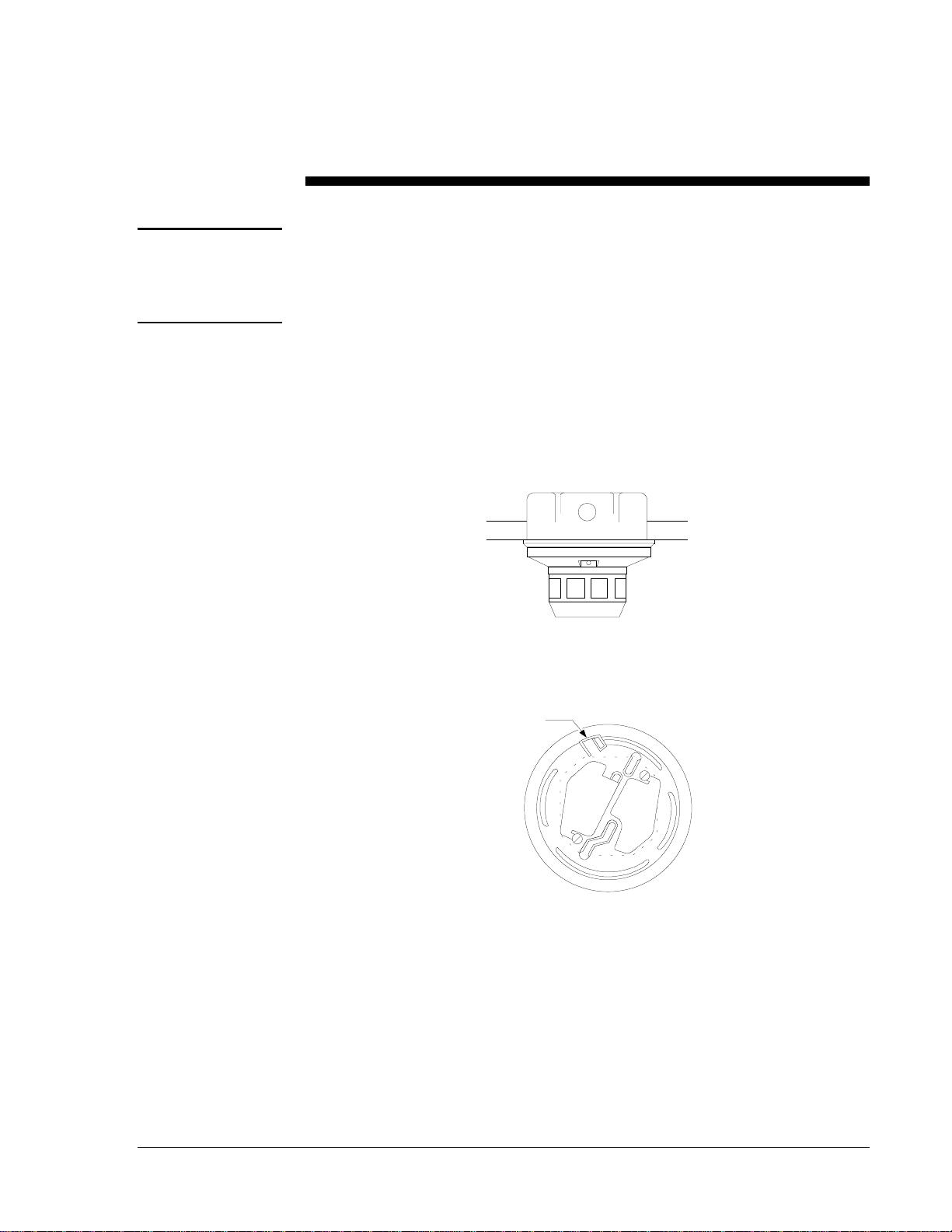
●directly to 3-1/2 inch (88.9 mm) or 4 inch (101.6 mm) octagonal box,
1-1/2 inch (38.1 mm) deep electrical box (Figure 1)
●to a 4 inch (101.6 mm) square electrical box using the plaster ring
with the supplied mounting bracket kit
flmount2
Figure 1: Flush Mounting of 2412/2424 Smoke Detector
on 3-1/2 Inch and 4 Inch Octagonal Box
Tamper
Resistant Tab
mountbrk
Figure 2: 2412/2424 Smoke Detector Mounting Bracket
To make detector tamper-proof, break off the tab extension at the scribed
line (Figure 2). For more information, refer to the Tamper-Proof Feature
section in this technical bulletin.
General
Information
Mounting

8 Conventional Products—2412, 2412TH, 2424, and 2424TH Direct Wire Photoelectronic Smoke Detectors
NFPA-72-National Fire Alarm Code defines the spacing requirements for
smoke detectors. Typically, this is 30 feet when the detectors are installed
on a smooth ceiling. Room configuration and operating environment may
require a reduction in the standard maximum 900 square foot coverage for
each detector. However, all installations must comply NFPA-72-National
Fire Alarm Code and/or special requirements of the authority having
jurisdiction.
All wiring must be installed in compliance with the National Electrical
Code, all applicable local codes, and any special requirements of the local
authority having jurisdiction. Proper wire gauges should be used. The
conductors used to connect smoke detectors to control panels and
accessory devices should be color-coded to reduce the likelihood of wiring
errors. Improper connections can prevent a system from responding
properly in the event of a fire.
For Initiating Device Circuit (IDC) wiring (the wiring between
interconnected detectors as well as the control panel), it is recommended
that the wire be no smaller than No. 18 American Wire Gauge (AWG)
(1.0 square mm). However, the screws and clamping plate in the detector
can accommodate wire sizes up to No. 12 AWG (3.3 square mm). The use
of twisted pair wiring for the detection/power (+ and -) wires is
recommended to minimize the effects of electrical interference.
Smoke detectors and alarm system control panels have specifications for
allowable IDC resistance. Consult the control panel manufacturer’s
specifications for the total IDC resistance allowed for the control panel
being used before wiring the detector IDC circuit.
To make wire connections:
1. Strip about 3/8 inch of insulation from the end of the wire.
2. Slide the bare end of the wire under the clamping plate.
3. Tighten the clamping plate screw.
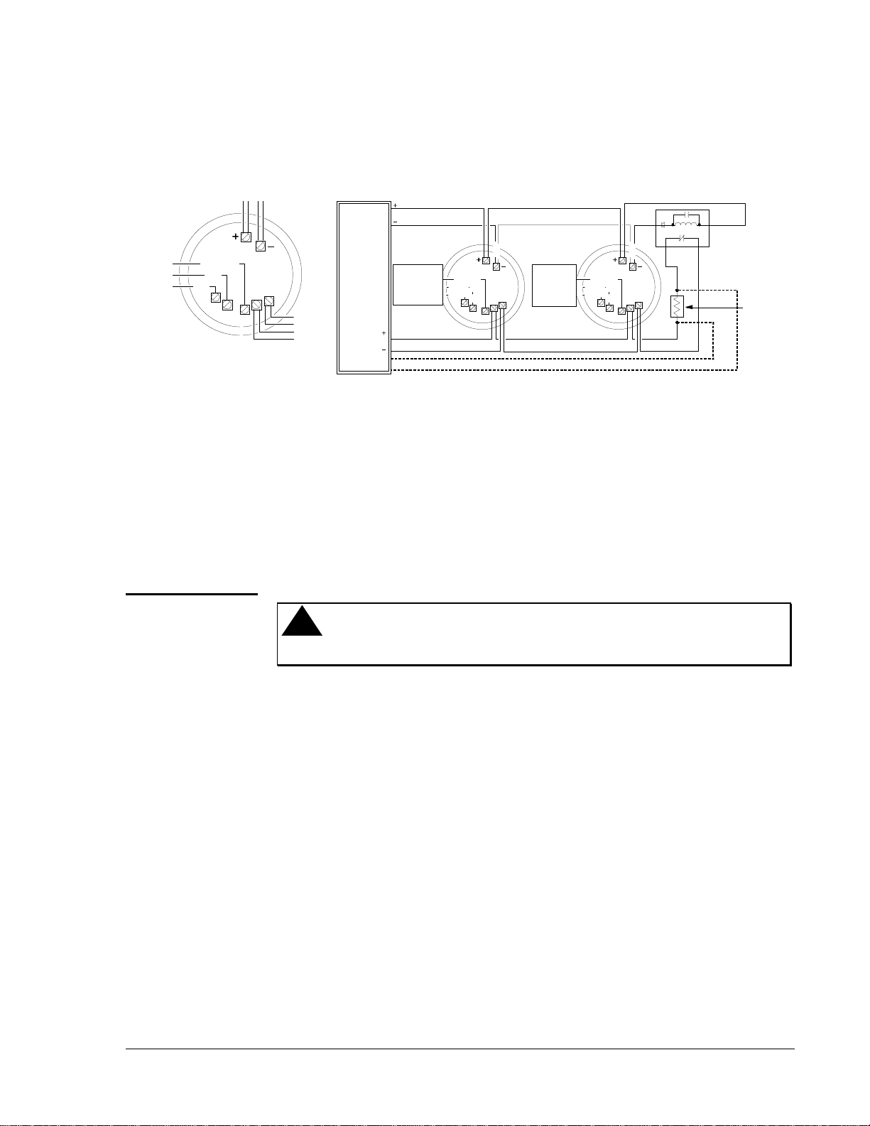
Note: For system supervision, do not loop wire under Terminals 1 and 2.
This NotThis
wirguide
Figure 3: Electrical Connections
Note: If remote annunciator is not used, polarity to the detector may be
reversed.
Spacing
Wiring
Installation
Guidelines
Conventional Products—2412, 2412TH, 2424, and 2424TH Direct Wire Photoelectronic Smoke Detectors 9
Please note carefully the wiring diagram for a typical 4-wire detector
system shown in Figure 4. Contacts are shown in standby mode and will
transfer in alarm condition.
Figure 4: Wiring Diagram for the 2412/2424 Series Detector Used
with a 4-Wire Control Panel
The detectors are marked with a compatibility identifier located as the last
digit of a five-digit code stamped on the back of the product. Connect
detectors only to compatible control units as indicated in the Device
Compatibility Technical Bulletin in the Fire Management Accessories
Manual (FAN 445).
!
WARNING: Shock hazard. Remove power from IDCs before
installing detectors.
1. Mount the detector mounting bracket to the electrical backbox.
2. Enable the tamper-proof feature. For instructions see the
Tamper-Proof Feature section of this technical bulletin.
3. Wire the detector following the Wiring Installation Guidelines.
4. Line up arrows on the detector with arrows on the mounting bracket.
5. Turn the detector clockwise until it clicks into place.
6. After all detectors have been installed, apply power to the control unit.
7. Test the detector as described in the Testing section of this
technical bulletin.
8. Reset the detector at the system control panel.
9. Notify the proper authorities that the system is in operation.
smkwire2
Class A O ptional W irin
g
EOL Power
Supervision
Rela
y
Module...
Su
g
g
ested
EOL
Resistor
Power to
Detectors
UL Listed
Control
Panel
IDC
2
1
4
5
6
78
Common
N/O
N/C
Alarm
Contacts
Form-A
N/O
Auxiliar
y
Contacts
Form-C
Power
3
2
1
4
5
6
78
Common
N/O
N/C
(Optional)
Releasing
Devices
3
2
1
4
5
6
7
8
Common
N/O
N/C
(Optional)
Releasing
Devices
Installation

10 Conventional Products—2412, 2412TH, 2424, and 2424TH Direct Wire Photoelectronic Smoke Detectors
Dust covers can be used to help limit dust entry to the detector, but they
are not a substitute for removing the detector during building construction.
If detectors are mounted in a construction area, with or without the dust
cover in place, each detector should be thoroughly cleaned, inspected, and
tested after construction is complete. Remove any dust covers before
placing the system in service.
This detector includes a tamper-proof feature that prevents removal of the
detector without the use of a tool.
To make the detector tamper-proof:
1. Break off the smaller tab at the scribed line on the tamper-proof tab on
the detector mounting bracket (Figure 2).
2. Install the detector.
To remove the detector from the bracket once it has been made
tamper-proof:
1. Use a small screwdriver to depress the tamper-proof tab located in the
slot on the mounting bracket.
2. Turn the detector counterclockwise for removal.
The tamper-proof feature may be defeated by breaking and removing
the plastic lever from the base. However, this prevents using the
feature again.
Tamper-Proof
Slot
dirwirtm
Mountin
g
Bracket
Mountin
g
Screw
Mountin
g
.....
Screw.....
Figure 5: Tamper-Proof Slot
Limiting
Exposure to Dust
Tamper-Proof
Feature

Conventional Products—2412, 2412TH, 2424, and 2424TH Direct Wire Photoelectronic Smoke Detectors 11
Testing and Maintenance
Procedures
Before testing, notify the proper authorities that the smoke detector system
is undergoing maintenance and will be temporarily out of service. Disable
the zone or system undergoing maintenance to prevent unwanted alarms.
After a detector is set into alarm by one of the following test methods and
the alarm activating device is removed from the detector, the system
should be reset at the control panel before testing any additional detectors.
After all testing is complete and the system is returned to its normal
configuration, notify the proper authorities that the system is back in
service.
All detectors must be tested after installation and periodically thereafter.
Testing methods must satisfy the authority having jurisdiction. Detectors
offer maximum performance when they are tested and maintained in
compliance with National Fire Protection Association (NFPA)
72-National Fire Alarm Code.
Before testing the detector, check to ensure that the LEDs are blinking.
If they are not, the detector has lost power (check the wiring) of it is
defective (return it for repair).
Functional Test--Recessed Test Switch
1. Find the test switch is located on the detector housing (Figure 6).
2. Press and hold the recessed test switch with a 0.1 inch maximum
diameter tool. The LED on the detector should light and report an
alarm condition to the control panel on the IDC within five seconds.
Calibrated Test Card (R59-18-00)
1. Remove the detector cover by placing a small bladed screwdriver in
the side slot of the detector cover.
2. Twist it slightly until the cover can be turned counterclockwise for
removal.
3. Insert the NO ALARM end of the test card fully into the test slot
(Figure 7), then slide it counterclockwise until it stops. The detector
should not alarm after 20 seconds.
4. Remove the test card by sliding it clockwise before removing.
Testing
Testing the 2412
and 2424 Series
Detectors

12 Conventional Products—2412, 2412TH, 2424, and 2424TH Direct Wire Photoelectronic Smoke Detectors
5. Insert the ALARM end.
6. Check that the LED latches on within 20 seconds, indicating alarm
and annunciating the panel.
7. Put the cover back by gently rotating it clockwise until it locks
in place.
testswc3
Test Module
Socket
LED
Push recessed test switch
with a 0.1 inch max. diameter tool.
Recessed
TestSwitch
Figure 6: Top and Side Views Showing Position of Test Switch
Test Module (MOD400R or MOD400)
The MOD400R or MOD400 test module is used with an analog or digital
voltmeter to check the detector sensitivity as described in the test module
manual.
Aerosol Generator (Gemini 501)
1. Set the aerosol generator to represent 4%/ft to 5%/ft obscuration as
described in the Gemini 501 manual.
2. Use the bowl-shaped applicator to apply aerosol until unit alarms.
3. Clean and retest detectors that fail these tests as described in the
Maintenance section of this technical bulletin.
4. Return the detectors for repair if they still fail these tests.
5. Notify the proper authorities that the system is back online.

Conventional Products—2412, 2412TH, 2424, and 2424TH Direct Wire Photoelectronic Smoke Detectors 13
Direct Heat Test (Models 2412TH and 2424TH only)
To test the bimetallic thermal collector on the models 2412TH and
2424TH, follow these instructions:
1. Use a low powered heat gun or blow dryer, and aim the heat source
across the detector.
2. Hold the heat source about 12 inches (30 cm) from the detector to
avoid damaging the plastic. When the heat rises to greater than
135°F, the detector will latch in alarm.
3. After the test, the bimetallic collector will self-restore.
Detectors that fail these tests should be cleaned as described in the
Maintenance section of this technical bulletin and retested. If the detectors
still fail these tests, they should be replaced or returned for repair.
Notify the proper authorities that the system is back online when tests are
complete.

14 Conventional Products—2412, 2412TH, 2424, and 2424TH Direct Wire Photoelectronic Smoke Detectors
Detectors should be cleaned and tested after exposure to smoke or fire.
Before removing the detector, notify the proper authorities that the smoke
detector system is undergoing maintenance and will be temporarily out of
service. Disable the zone or system undergoing maintenance to prevent
unwanted alarms. After maintenance is performed on a detector, it should
be functionally tested to assure proper operation.
After maintenance and testing is complete and the system is returned to its
normal configuration, notify the proper authorities that the system is again
in service.
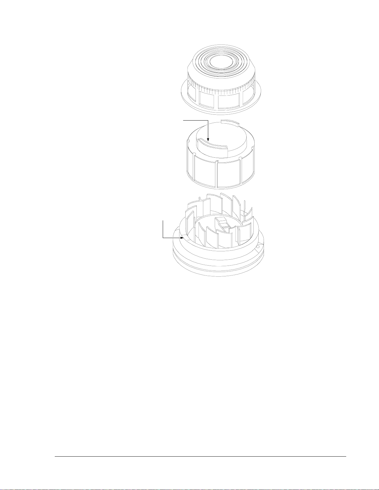
1. Remove the detector cover by placing a small bladed screwdriver in
the side slot of the detector cover (Figure 7).
2. Twist it slightly until the cover can be turned counterclockwise for
removal.
3. Vacuum the screen carefully without removing it. If further cleaning
is required, continue with Step 4 otherwise skip to Step 9.
4. Remove the screen by pulling it straight out (Figure 7).
5. Vacuum the inside.
6. Clean the vaned chamber piece by vacuuming or blowing out dust and
particles.
7. Replace the screen. Align the arrow on top with the test module
socket of the detector.
8. Carefully push the screen onto the base, making sure it fits tightly to
the chamber.
9. Replace the cover by gently rotating it clockwise until it locks in
place.
10. After cleaning a detector, test the detector with the Calibrated Test
Card (Model R59-18-00) as previously described.
11. Notify the proper authorities that the system is back online.
Maintenance
Cleaning the 2412
and 2424 Series
Detectors
Conventional Products—2412, 2412TH, 2424, and 2424TH Direct Wire Photoelectronic Smoke Detectors 15
cov&scr5
Removable
Head Cover
Cleanable Screen
P/N RS24
(
w/o Thermal
)
.....
Test Slot
Vaned Chamber
Head Cover
RemovalSlot
Figure 7: Removal of Cover and Screen for Cleaning

16 Conventional Products—2412, 2412TH, 2424, and 2424TH Direct Wire Photoelectronic Smoke Detectors
This smoke detector is designed to activate and initiate emergency action,
but will do so only when used in conjunction with other equipment.
This detector is designed for installation in accordance with NFPA
Standards 71 and 72.
●Smoke detectors cannot work without power. Alternating Current
(AC) or Direct Current (DC) powered smoke detectors will not work
if the power supply is cut off for any reason.
●Smoke detectors will not sense fires which start where smoke does
not reach the detectors. Smoke from fires in chimneys, in walls, on
roofs, or on the other side of closed doors may not reach the smoke
detector and alarm it.
●A detector may not detect a fire developing on another level of a
building. For this reason, detectors should be located on every level
of a building.
●Smoke detectors have sensing limitations. Ionization detectors offer a
broad range fire-sensing capability, but they are better at detecting
fast, flaming fires than slow, smoldering fires. Photoelectronic
detectors sense smoldering fires better than flaming fires. Because
fires develop in different ways, and are often unpredictable in their
growth, neither type of detector is always best, and a given detector
may not always provide warning of a fire. In general, detectors
cannot be expected to provide warnings for fires resulting from
inadequate fire protection practices, violent explosions, escaping gas,
improper storage of flammable liquids like cleaning solvents, other
safety hazards, or arson.
This detector is UL Listed to operate in a maximum air velocity of
3000 ft./min. Air velocity, along with other factors, may affect
detector sensitivity. See the 1993 NFPA-72-National Fire Alarm
Code, Appendix B for information.
●Test your smoke detector system per NFPA 72-National Fire Alarm
Code, or codes and standards specific to the country of installation, at
least semiannually. Clean and take care of your smoke detectors
regularly. Taking care of the fire detection system you have installed
will measurably reduce your product liability risks.
Limitations
Controls Group FAN 408
507 E. Michigan Street Fire Initiating Devices and Notification Appliances Technical Manual
P.O. Box 423 Printed in U.S.A.
Milwaukee, WI 53201
This manual suits for next models
5
Table of contents
Other Metasys Smoke Alarm manuals


