Specified Technologies EZ PATH 22 Series Assembly instructions

INSTALLING PATHWAY USING WALL PLATES
Prior to Pulling Cables
Device is installed through wall and attached using wall plates to sandwich the wall. No mechanical
attachment to wall itself is required.
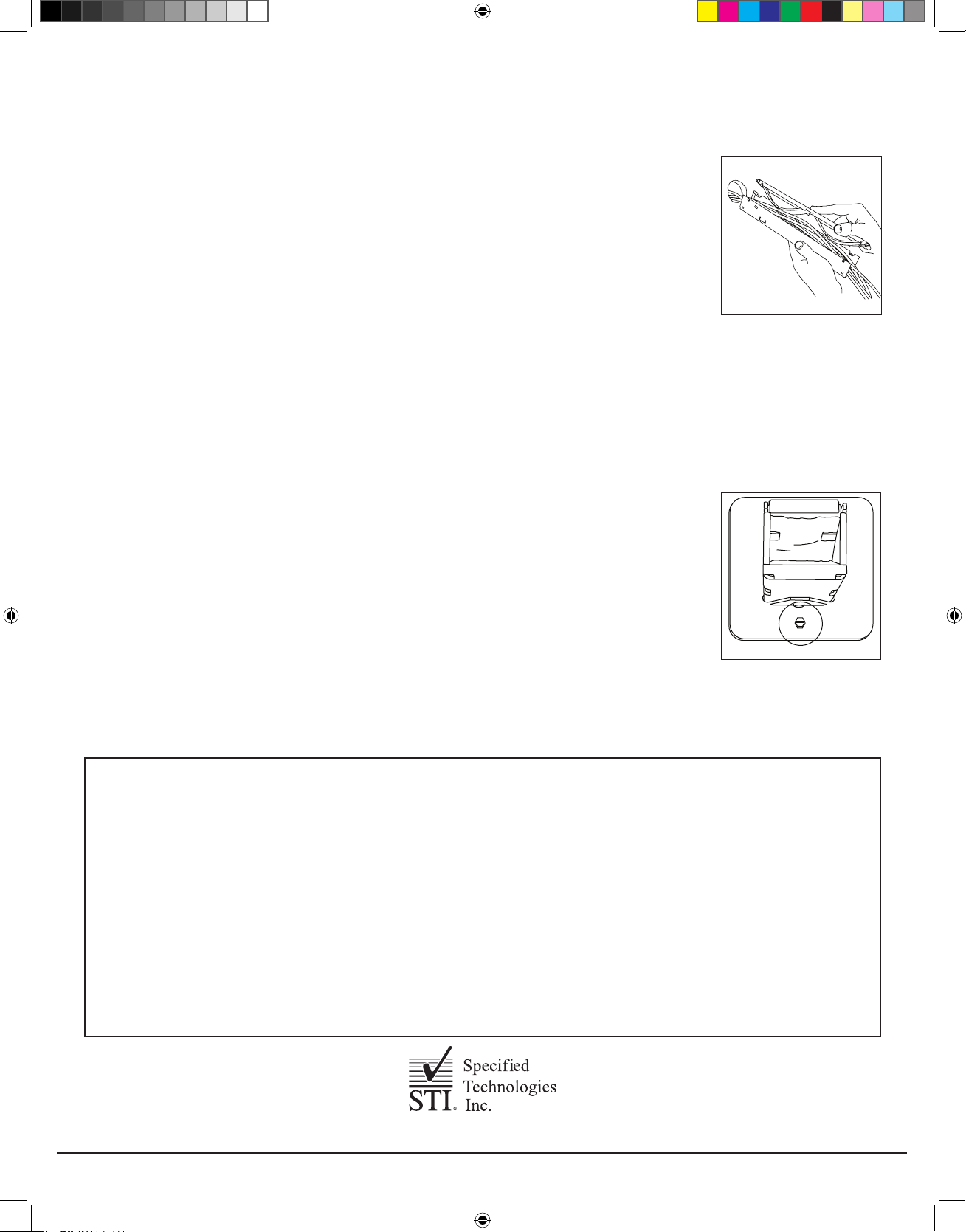
1. If necessary, pre-install required set screws in wall plates using Allen wrench (provided). NOTE:
Two set screws positioned and tightened at 90 degrees to each other in both plates will adequately
hold device (See Fig. 4).
2. Install a wall plate around pathway making sure that set screw flanges are facing towards the end
of the device. Adjust position of wall plate so that device will be centered within the wall (Fig. 5).
When properly adjusted, tighten set screws to lock plate onto pathway.
3. Place one of two provided gaskets around opposite end of pathway and carefully slide it back to
fit snugly against back side (wall side) of plate.
4. Insert pathway through wall (with black device label facing upwards) using previously installed wall
plate and gasket as a stop (See Fig. 6).
5. Moving to the opposite side of the wall, install remaining gasket around pathway and slide toward
wall.
6. Install remaining wall plate around pathway and slide it toward wall surface. While pulling path-
way toward you, push wall plate and gasket tightly to wall and tighten set screws. Check device
for excessive play. If device appears to be loose or can easily be moved, readjust wall plates
as necessary to tighten device firmly against wall.
CREATING THE OPENING
Gypsum Board Walls:
1. Locate suitable area of the wall to penetrate making sure that there are no studs, wires, pipes or
other obstructions located within wall.
2. a. Round Openings:
i.) Using a 2” (51 mm) hole saw, make an opening on each side of the wall ensuring that the holes
are aligned (See Fig. 1).
b. Square Openings (Optional):
i.) Mark a nom. 1-3/4” (44 mm) square opening. Make sure opening is square and plumb. The
inside opening of the wall plates can be used as a template (See Fig. 2).
ii.) Using a keyhole saw, cut wall board (See Fig. 3). Cutting to the outside of the line will pro-
duce a slightly over-sized opening. Mark and cut opposite side of the wall, exercising care to
align both openings.
3. Insert pathway and check for fit. Remove pathway.
4. Install device per instructions below.
Concrete or Masonry Walls:
1. Core drill a nom 2” (51 mm) round opening in wall or cut or form a nom 1-3/4” (44 mm) square opening.
2. Install device per instructions below.
INSTALLATION SHEET
Series 22
Fire Rated Pathway
ZIS1007 - 0766
GENERAL - READ COMPLETELY BEFORE INSTALLING
This product allows for several optional installation methods. Available
methods for walls are shown here. The pathway (device) consists of an
enclosed heavy gauge galvanized steel channel with a detachable lid. Wall
plates are designed to accommodate single device installations. Wall plates
and gaskets are included.
NOTE: WALL INSTALLATIONS REQUIRE THIS DEVICE TO BE
INSTALLED WITH THE TOP (LID) FACING UPWARD. The lid may be
identified by the device label.
FIG.1
FIG.2
FIG.3
FIG. 4
FIG. 5
FIG. 6
Table A: Parts List
Qty. Description
1 EZ Path®Series 22 Device 1 5/64 Allen Key
2 Wall Plates 2 Ground Screws
2 Intumescent Gaskets 10 8-2 x 1/4” Lg. Set Screws
Page 1 of 2 Installation Sheet • EZ PATH Series 22 ZIS1007 - 0766
ZIS1007 0766 EZD22.indd 1 3/16/16 9:17 AM
INSTALLING IN WALL OPENINGS USING SEALANT (NO WALL PLATES)
Installing Around Previously Installed Cables
1. Remove Lid: Lid is secured within the top of the U channel via an extruded boss that snaps into round holes located at both
ends on one side of the lid. A slot is provided between the cover and top of the channel next to each boss. Insert a flat-bladed
screw driver into the slots and carefully pry the channel open enough to release each boss.
Exercise care not to bend or distort the channel. Remove the cover by sliding it out of the slots
located on the opposite side of the lid.
2. Place pathway channel around cables (See Fig 7).
3. Replace lid by sliding lid into channel attachment tabs and applying pressure on opposite end until
the lid locks back into place.
4. Caulk using approved sealant (SpecSeal® SSS or LCI Series sealants, or Pensil® 300 Silicone
Sealant). Apply sealant to a depth of 5/8” within annulus on both sides of wall. Apply a 3/8” crown
bead at areas of point contact. In concrete walls, device may be cast or grouted using hydraulic
cement or SpecSeal® mortar.
INSTALLING or PULLING CABLES
A resilient liner provides an adjustable seal within the pathway device. Liner must be protected from damage while adding or removing
cables. Wrap cable ends with a suitable low friction tape before inserting into the pathway. Where cable lubricants are used, low solids,
water-based products are recommended. This device is designed to be fully functional at all cable loadings from completely empty
to visually filled, and cables should easily slide through the pathway using minimal effort. IF RESISTANCE IS ENCOUNTERED, DO
NOT FORCE CABLES OR CABLE BUNDLES THROUGH THE PATHWAY. DAMAGE MAY RESULT. Upper curved liner may be
depressed when inserting cables, if necessary, using a flat, smooth implement and then removing it after cables are installed. The
rectangular shape of the loading area coupled with gentle pressure exerted by resilient liners will naturally distribute the cables at a
relatively uniform height across the width of the device. The use of a cable dressing/combing instrument to straighten and organize
cables may help to maximize usable space within the pathway device.
GROUNDING
At the option of the installer, this device may be grounded. After device and wall plates have been
installed, insert ground screws where indicated on wall plate (See Fig. 8). NOTE: Wall plates must be
used if grounding is desired.
WALL LABELING
Wall labels are provided with the pathway. Orange colored label is intended to be used to identify the
pathway’s installer as well as to provide applicable UL System information. Two labels are provided for
marking both sides of wall.
MAINTENANCE
No maintenance of the pathway is normally required.
FIG. 7
FIG. 8
LIMITED WARRANTY: STI warrants that its products will be free of defects for one year from the date of purchase. In
the event a product does not conform to this warranty, the sole and exclusive remedy is, at STI’s option, replacement
of the product or refund of the purchase price. The warranty provided herein shall be void and of no effect in the
event that the product is not installed in accordance with STI’s published instructions, listed systems and applicable
building and safety codes. THIS WARRANTY IS IN LIEU OF ALL OTHER REPRESENTATIONS AND EXPRESSED
OR IMPLIED WARRANTIES (including the implied warranties of merchantability or fitness for a particular use) AND
UNDER NO CIRCUMSTANCES SHALL STI BE LIABLE FOR ANY DIRECT, INDIRECT, SPECIAL, INCIDENTAL
OR CONSEQUENTIAL DAMAGES OR LOSSES, INCLUDING, WITHOUT LIMITATION, ANY LOSS OF REVENUE,
PROFIT OR USE. Prior to use, the user shall determine the suitability of the product for its intended use, and the user
assumes all risks and liability for subsequent use. No person other than an officer of STI is authorized to bind STI to
any other warranty for any product for which this warranty is issued.
MADE IN THE USA – COPYRIGHT © 2016 SPECIFIED TECHNOLOGIES INC.
Page 2 of 2 Installation Sheet • EZ PATH Series 22 ZIS1007 - 0766
Somerville, NJ 08876 USA
T: 800.992.1180 • www.stifirestop.com
ZIS1007 0766 EZD22.indd 2 3/16/16 9:17 AM
Table of contents
Popular Industrial Equipment manuals by other brands


LUCOMA
LUCOMA RGK-10 Series Installation, operation and maintenance instructions

Jäger
Jäger Z80-K440.21 S5 manual

SCHUNK
SCHUNK VERO-S NSE plus 138 Translation of original operating manual

Clemco
Clemco BNP-65P manual

UNIFILLER
UNIFILLER Mini Dopositor Operation and Spare Parts Manual

Schäfter+Kirchhoff
Schäfter+Kirchhoff 60SMS Series manual

GUDEL
GUDEL TMO Series operating manual

Parker
Parker Airtek Smart Cycle Plus SCP1200 user guide

HAMAR LASER
HAMAR LASER L-705 manual

ABB
ABB HT574739 Operation manual

Rockwell Automation
Rockwell Automation Allen-Bradley Bulletin 2364E user manual

Endress+Hauser
Endress+Hauser HART Field Xpert operating instructions